buttons NISSAN TERRANO 2004 Service Repair Manual
[x] Cancel search | Manufacturer: NISSAN, Model Year: 2004, Model line: TERRANO, Model: NISSAN TERRANO 2004Pages: 1833, PDF Size: 53.42 MB
Page 6 of 1833

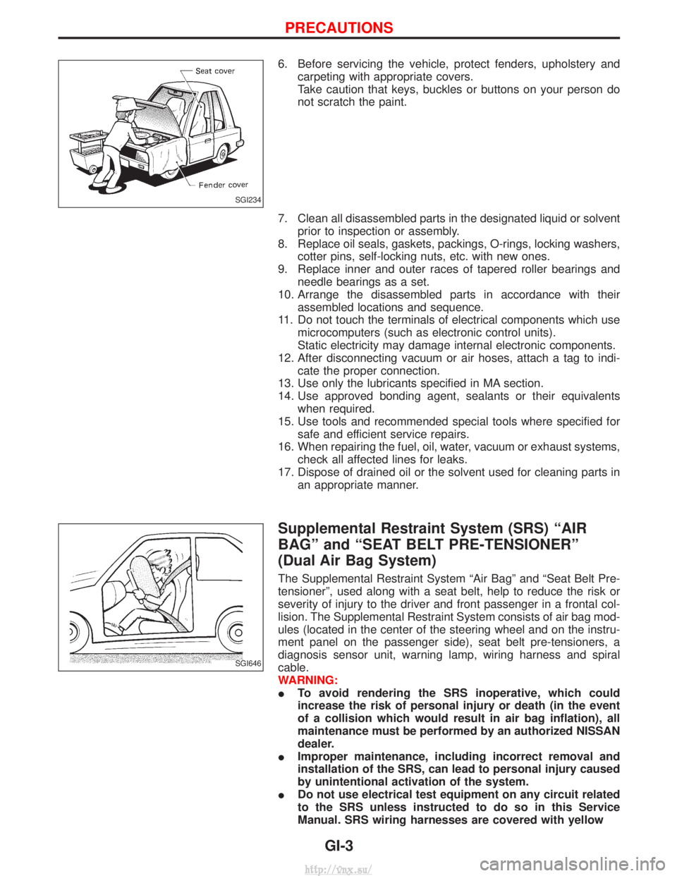
6. Before servicing the vehicle, protect fenders, upholstery andcarpeting with appropriate covers.
Take caution that keys, buckles or buttons on your person do
not scratch the paint.
7. Clean all disassembled parts in the designated liquid or solvent prior to inspection or assembly.
8. Replace oil seals, gaskets, packings, O-rings, locking washers, cotter pins, self-locking nuts, etc. with new ones.
9. Replace inner and outer races of tapered roller bearings and needle bearings as a set.
10. Arrange the disassembled parts in accordance with their assembled locations and sequence.
11. Do not touch the terminals of electrical components which use microcomputers (such as electronic control units).
Static electricity may damage internal electronic components.
12. After disconnecting vacuum or air hoses, attach a tag to indi- cate the proper connection.
13. Use only the lubricants specified in MA section.
14. Use approved bonding agent, sealants or their equivalents when required.
15. Use tools and recommended special tools where specified for safe and efficient service repairs.
16. When repairing the fuel, oil, water, vacuum or exhaust systems, check all affected lines for leaks.
17. Dispose of drained oil or the solvent used for cleaning parts in an appropriate manner.
Supplemental Restraint System (SRS) ªAIR
BAGº and ªSEAT BELT PRE-TENSIONERº
(Dual Air Bag System)
The Supplemental Restraint System ªAir Bagº and ªSeat Belt Pre-
tensionerº, used along with a seat belt, help to reduce the risk or
severity of injury to the driver and front passenger in a frontal col-
lision. The Supplemental Restraint System consists of air bag mod-
ules (located in the center of the steering wheel and on the instru-
ment panel on the passenger side), seat belt pre-tensioners, a
diagnosis sensor unit, warning lamp, wiring harness and spiral
cable.
WARNING:
ITo avoid rendering the SRS inoperative, which could
increase the risk of personal injury or death (in the event
of a collision which would result in air bag inflation), all
maintenance must be performed by an authorized NISSAN
dealer.
I Improper maintenance, including incorrect removal and
installation of the SRS, can lead to personal injury caused
by unintentional activation of the system.
I Do not use electrical test equipment on any circuit related
to the SRS unless instructed to do so in this Service
Manual. SRS wiring harnesses are covered with yellow
SGI234
SGI646
PRECAUTIONS
GI-3
http://vnx.su/
Page 1583 of 1833

Combination Meter Self-Diagnosis
PERFORMING SELF-DIAGNOSIS MODE
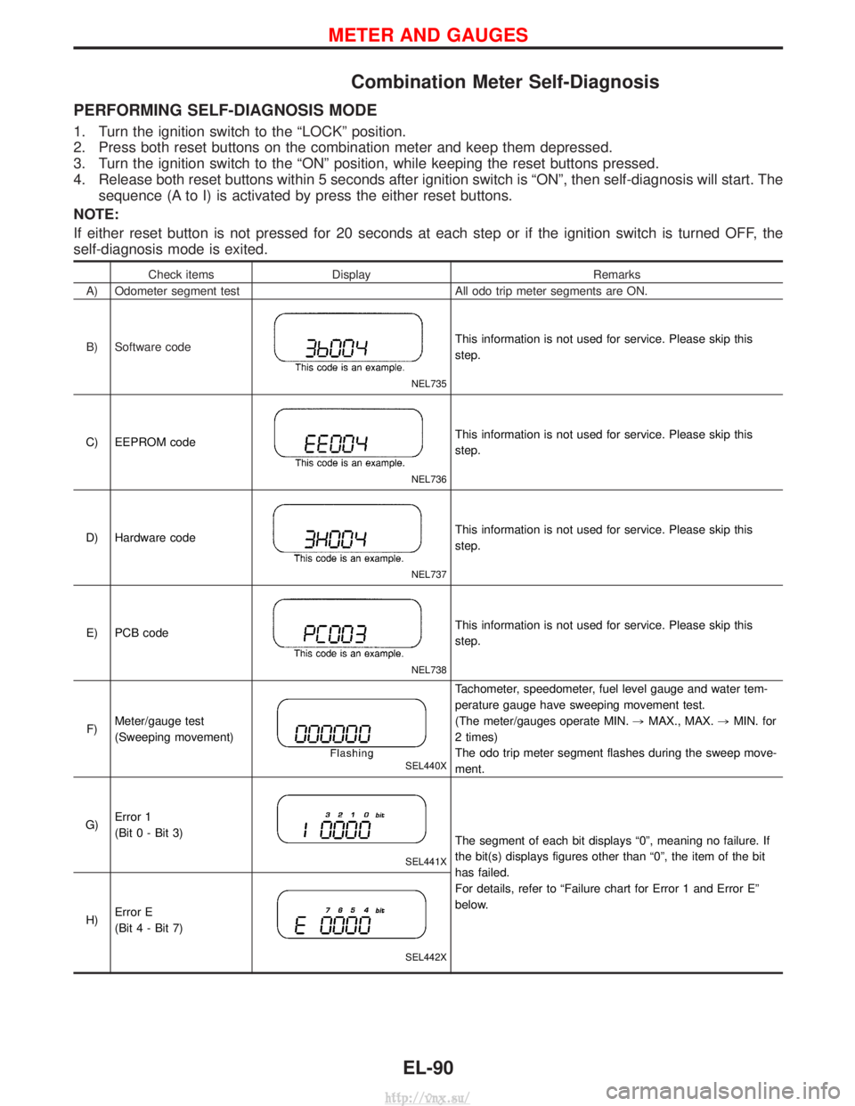
1. Turn the ignition switch to the ªLOCKº position.
2. Press both reset buttons on the combination meter and keep them depressed.
3. Turn the ignition switch to the ªONº position, while keeping the reset buttons pressed.
4. Release both reset buttons within 5 seconds after ignition switch is ªONº, then self-diagnosis will start. Thesequence (A to I) is activated by press the either reset buttons.
NOTE:
If either reset button is not pressed for 20 seconds at each step or if the ignition switch is turned OFF, the
self-diagnosis mode is exited.
Check items Display Remarks
A) Odometer segment test All odo trip meter segments are ON.
B) Software code
NEL735
This information is not used for service. Please skip this
step.
C) EEPROM code
NEL736
This information is not used for service. Please skip this
step.
D) Hardware code
NEL737
This information is not used for service. Please skip this
step.
E) PCB code
NEL738
This information is not used for service. Please skip this
step.
F) Meter/gauge test
(Sweeping movement)
SEL440X
Tachometer, speedometer, fuel level gauge and water tem-
perature gauge have sweeping movement test.
(The meter/gauges operate MIN.
,MAX., MAX. ,MIN. for
2 times)
The odo trip meter segment flashes during the sweep move-
ment.
G) Error 1
(Bit 0 - Bit 3)
SEL441X
The segment of each bit displays ª0º, meaning no failure. If
the bit(s) displays figures other than ª0º, the item of the bit
has failed.
For details, refer to ªFailure chart for Error 1 and Error Eº
below.
H) Error E
(Bit 4 - Bit 7)
SEL442X
METER AND GAUGES
EL-90
http://vnx.su/
Page 1584 of 1833

Check itemsDisplay Remarks
I) Fuel warning lamp test
SEL443X
Fuel warning lamp is on and odo trip meter segment ªFUELº
flashes.
Failure Chart for ªError 1º and ªError Eº
Bit Detectable items Description of the failureDisplayed figure on the
bit
Failure No failure
0 Speedometer input
signal
No input signal
When no signal is detected for 30 minutes continuously with
the ignition ON, it should be judged as signal failure.
(If input signal is detected later, then the judgement will be
canceled immediately.) 1
0
Abnormal input signal
When any signal of frequency which would not exist in normal
conditions is detected, it should be judged as signal failure. 2
1 Tachometer input
signal
No input signal
When no signal is detected for 30 minutes continuously with
the ignition ON, it should be judged as signal failure.
(If input signal is detected later, then the judgement will be
canceled immediately.) 1
0
Abnormal input signal
When any signal of frequency which would not exist in normal
conditions is detected, it should be judged as signal failure. 2
2 Fuel level input sig-
nal
Short circuit
When short circuit of the signal line is detected for 5 seconds
or more, it should be judged as short-circuit failure. 1
0
Open circuit
When open circuit of the signal line is detected for 5 seconds
or more, it should be judged as open-circuit failure. 2
3 Water temperature
input signal Short circuit
When short circuit of the signal line is detected for 5 seconds
or more, it should be judged as short-circuit failure. 10
4 Outside air tempera-
ture input signal
Short circuit
When short circuit of the signal line is detected for 5 seconds
or more, it should be judged as short-circuit failure. 1
0
Open circuit
When open circuit of the signal line is detected for 5 seconds
or more, it should be judged as open-circuit failure. 2
5 Reset buttons Short circuit for reset buttons
When the short circuit is continu-
ously detected for 5 minutes or
more, it should be judged as
short-circuit failure. Right side reset button has
failed.
1
0
Left side reset button has
failed. 2
Both reset buttons have
failed. 3
6Ð Ð 00
7 CPU EEPROM failure 1
0
CPU RAM failure 2
METER AND GAUGES
Combination Meter Self-Diagnosis (Cont'd)
EL-91
http://vnx.su/
Page 1628 of 1833

Service instruction
ItemRadio linked with IMMU and/or SECU
Battery disconnection No additional action required
Radio needs repair Repair needs to be done by authorised representative of radio manufacturer since radio cannot be operated unless it is reset to NEW state, using special decoding equipment
Replacement of radio by new part Radio is delivered in NEW state. If possible, the radio will automatically link up with the immobiliser system. If this appears not possible, CATS code needs to be manually input
Transferring radio to another vehicle/
replacement of radio by an ªoldº part Radio needs to be reset to NEW state by authorised representative of radio manufac-
turer
Replacement of IMMU by new part Radio will request for CATS code input prior to establishing the link with the IMMU
Replacement of IMMU by old part If a radio code has already been stored in memory of the IMMU, the radio cannot be linked to it. After switching on the radio, it will display ªSECUREº after 1 minute. Opera-
tion can only be established after resetting the ratio by an authorised representative of
radio manufacturer
CATS code input procedure
1. Radio displays ªCODE INº after the power is switched ON.
2. Enter CATS code (4-digits) by pressing the preset buttons (using 1 to 4).Press the preset buttons for the necessary amount of times for the number of each digits.
e.g. CATS code is ª5432º
Press No. 1 preset button for 5 times
Press No. 2 preset button for 4 times
Press No. 3 preset button for 3 times
Press No. 4 preset button for 2 times
3. Press the
button.
4. If the code is OK, the radio will power ON. If the code is NG, the radio will be locked up as below. After the lock up, the radio will display ªCODE INº
again.
1st to 3rd attempt: The radio will be locked for 10 seconds after each attempt
4th to 20th attempt: The radio will be locked for 60 minutes after each attempt
Over 20th attempt: The radio will be locked completely
SPEED DEPENDENT VOLUME CONTROL
Description
If activated, the radio output volume will be automatically adjusted to compensate for increased driving noises
at higher driving speeds. The radio receives a speed signal from the combination meter and selects the out-
put volume.
AUDIO
System Description (Cont'd)
EL-135
http://vnx.su/