Ecm NISSAN TIIDA 2007 Service Owner's Manual
[x] Cancel search | Manufacturer: NISSAN, Model Year: 2007, Model line: TIIDA, Model: NISSAN TIIDA 2007Pages: 5883, PDF Size: 78.95 MB
Page 75 of 5883
![NISSAN TIIDA 2007 Service Owners Manual AV-70
< COMPONENT DIAGNOSIS >[AUDIO WITH NAVIGATION]
U1210 NAVI CONTROL UNIT
U1210 NAVI CONTROL UNIT
DescriptionINFOID:0000000001728695
DTC LogicINFOID:0000000001728696
Diagnosis ProcedureINFOID:00000](/img/5/57395/w960_57395-74.png "NISSAN TIIDA 2007 Service Owners Manual AV-70
< COMPONENT DIAGNOSIS >[AUDIO WITH NAVIGATION]
U1210 NAVI CONTROL UNIT
U1210 NAVI CONTROL UNIT
DescriptionINFOID:0000000001728695
DTC LogicINFOID:0000000001728696
Diagnosis ProcedureINFOID:00000")
AV-70
< COMPONENT DIAGNOSIS >[AUDIO WITH NAVIGATION]
U1210 NAVI CONTROL UNIT
U1210 NAVI CONTROL UNIT
DescriptionINFOID:0000000001728695
DTC LogicINFOID:0000000001728696
Diagnosis ProcedureINFOID:0000000001728697
1.PERFORM THE SELF-DIAGNOSIS
1. Delete the self-diagnosis results. Turn ignition switch OFF.
2. Turn ignition switch ON. Replace map DVD-ROM with a normal one.
3. Perform the self-diagnosis again.
4. Check that the DTC is detected again.
Is any DTC detected?
YES >> Replace NAVI control unit.
NO >> Replace Map disc.
Part name Description
NAVI CONTORL UNIT Map data can be read from the map DVD-ROM by installing map DVD-ROM.
It is the master unit of the MULTI AV system, and it is connected to each control
unit by means of communication. It operates each system according to com-
munication signals from the NAVI control unit.
The NAVI control unit includes the audio, hands-free phone, navigation, and
vehicle information functions.
It is connected to ECM and combination meter via CAN communication to ob-
tain necessary information for the vehicle information function.
It inputs the illumination signals that are required for the display dimming con-
trol.
It inputs the signals for driving status recognition (vehicle speed, reverse and
parking brake).
MAP DVD-ROM A collection of map data
DTCDisplay contents of
CONSULT-IIIDTC Detection Condition Probable malfunction location
U1210DVD-ROM SEEK
[U1210] Malfunction is detected on DVD-ROM drive pickup lens
in NAVI control unit.
There is dirt and damage on the map disc.Map disc
NAVI control unit
Page 76 of 5883
![NISSAN TIIDA 2007 Service Owners Manual AV
U1211 NAVI CONTROL UNIT
AV-71
< COMPONENT DIAGNOSIS >[AUDIO WITH NAVIGATION]
C
D
E
F
G
H
I
J
K
L
MB A
O
P
U1211 NAVI CONTROL UNIT
DescriptionINFOID:0000000001728698
DTC LogicINFOID:0000000001728699](/img/5/57395/w960_57395-75.png "NISSAN TIIDA 2007 Service Owners Manual AV
U1211 NAVI CONTROL UNIT
AV-71
< COMPONENT DIAGNOSIS >[AUDIO WITH NAVIGATION]
C
D
E
F
G
H
I
J
K
L
MB A
O
P
U1211 NAVI CONTROL UNIT
DescriptionINFOID:0000000001728698
DTC LogicINFOID:0000000001728699")
AV
U1211 NAVI CONTROL UNIT
AV-71
< COMPONENT DIAGNOSIS >[AUDIO WITH NAVIGATION]
C
D
E
F
G
H
I
J
K
L
MB A
O
P
U1211 NAVI CONTROL UNIT
DescriptionINFOID:0000000001728698
DTC LogicINFOID:0000000001728699
Diagnosis ProcedureINFOID:0000000001728700
1.PERFORM THE SELF-DIAGNOSIS
1. Delete the self-diagnosis results. Turn ignition switch OFF.
2. Turn ignition switch ON. Replace map DVD-ROM with a normal one.
3. Perform the self-diagnosis again.
4. Check that the DTC is detected again.
Is any DTC detected?
YES >> Replace NAVI control unit.
NO >> Replace Map disc.
Part name Description
NAVI CONTORL UNIT Map data can be read from the map DVD-ROM by installing map DVD-ROM.
It is the master unit of the MULTI AV system, and it is connected to each control
unit by means of communication. It operates each system according to com-
munication signals from the NAVI control unit.
The NAVI control unit includes the audio, hands-free phone, navigation, and
vehicle information functions.
It is connected to ECM and combination meter via CAN communication to ob-
tain necessary information for the vehicle information function.
It inputs the illumination signals that are required for the display dimming con-
trol.
It inputs the signals for driving status recognition (vehicle speed, reverse and
parking brake).
MAP DVD-ROM A collection of map data
DTCDisplay contents of
CONSULT-IIIDTC Detection Condition Probable malfunction location
U1211DVD-ROM ERR COR-
RECTION [U1211] Malfunction is detected on DVD-ROM drive pickup lens
in NAVI control unit.
There is dirt and damage on the map disc. Map disc
NAVI control unit
Page 77 of 5883
![NISSAN TIIDA 2007 Service Owners Manual AV-72
< COMPONENT DIAGNOSIS >[AUDIO WITH NAVIGATION]
U1212 NAVI CONTROL UNIT
U1212 NAVI CONTROL UNIT
DescriptionINFOID:0000000001728701
DTC LogicINFOID:0000000001728702
Diagnosis ProcedureINFOID:00000](/img/5/57395/w960_57395-76.png "NISSAN TIIDA 2007 Service Owners Manual AV-72
< COMPONENT DIAGNOSIS >[AUDIO WITH NAVIGATION]
U1212 NAVI CONTROL UNIT
U1212 NAVI CONTROL UNIT
DescriptionINFOID:0000000001728701
DTC LogicINFOID:0000000001728702
Diagnosis ProcedureINFOID:00000")
AV-72
< COMPONENT DIAGNOSIS >[AUDIO WITH NAVIGATION]
U1212 NAVI CONTROL UNIT
U1212 NAVI CONTROL UNIT
DescriptionINFOID:0000000001728701
DTC LogicINFOID:0000000001728702
Diagnosis ProcedureINFOID:0000000001728703
1.PERFORM THE SELF-DIAGNOSIS
1. Delete the self-diagnosis results. Turn ignition switch OFF.
2. Turn ignition switch ON. Replace map DVD-ROM with a normal one.
3. Perform the self-diagnosis again.
4. Check that the DTC is detected again.
Is any DTC detected?
YES >> Replace NAVI control unit.
NO >> Replace Map disc.
Part name Description
NAVI CONTORL UNIT Map data can be read from the map DVD-ROM by installing map DVD-ROM.
It is the master unit of the MULTI AV system, and it is connected to each control
unit by means of communication. It operates each system according to com-
munication signals from the NAVI control unit.
The NAVI control unit includes the audio, hands-free phone, navigation, and
vehicle information functions.
It is connected to ECM and combination meter via CAN communication to ob-
tain necessary information for the vehicle information function.
It inputs the illumination signals that are required for the display dimming con-
trol.
It inputs the signals for driving status recognition (vehicle speed, reverse and
parking brake).
MAP DVD-ROM A collection of map data
DTCDisplay contents of
CONSULT-IIIDTC Detection Condition Probable malfunction location
U1212DVD-ROM DATA FOR-
WARD [U1212] Malfunction is detected on DVD-ROM drive pickup lens
in NAVI control unit.
There is dirt and damage on the map disc.Map disc
NAVI control unit
Page 78 of 5883
![NISSAN TIIDA 2007 Service Owners Manual AV
U1213 NAVI CONTROL UNIT
AV-73
< COMPONENT DIAGNOSIS >[AUDIO WITH NAVIGATION]
C
D
E
F
G
H
I
J
K
L
MB A
O
P
U1213 NAVI CONTROL UNIT
DescriptionINFOID:0000000001728704
DTC LogicINFOID:0000000001728705](/img/5/57395/w960_57395-77.png "NISSAN TIIDA 2007 Service Owners Manual AV
U1213 NAVI CONTROL UNIT
AV-73
< COMPONENT DIAGNOSIS >[AUDIO WITH NAVIGATION]
C
D
E
F
G
H
I
J
K
L
MB A
O
P
U1213 NAVI CONTROL UNIT
DescriptionINFOID:0000000001728704
DTC LogicINFOID:0000000001728705")
AV
U1213 NAVI CONTROL UNIT
AV-73
< COMPONENT DIAGNOSIS >[AUDIO WITH NAVIGATION]
C
D
E
F
G
H
I
J
K
L
MB A
O
P
U1213 NAVI CONTROL UNIT
DescriptionINFOID:0000000001728704
DTC LogicINFOID:0000000001728705
Diagnosis ProcedureINFOID:0000000001728706
1.PERFORM THE SELF-DIAGNOSIS
1. Delete the self-diagnosis results. Turn ignition switch OFF.
2. Turn ignition switch ON. Replace map DVD-ROM with a normal one.
3. Perform the self-diagnosis again.
4. Check that the DTC is detected again.
Is any DTC detected?
YES >> Replace NAVI control unit.
NO >> Replace Map disc.
Part name Description
NAVI CONTORL UNIT Map data can be read from the map DVD-ROM by installing map DVD-ROM.
It is the master unit of the MULTI AV system, and it is connected to each control
unit by means of communication. It operates each system according to com-
munication signals from the NAVI control unit.
The NAVI control unit includes the audio, hands-free phone, navigation, and
vehicle information functions.
It is connected to ECM and combination meter via CAN communication to ob-
tain necessary information for the vehicle information function.
It inputs the illumination signals that are required for the display dimming con-
trol.
It inputs the signals for driving status recognition (vehicle speed, reverse and
parking brake).
MAP DVD-ROM A collection of map data
DTCDisplay contents of
CONSULT-IIIDTC Detection Condition Probable malfunction location
U1213DVD-ROM DATA
[U1213] Malfunction is detected on DVD-ROM drive pickup lens
in NAVI control unit.
There is dirt and damage on the map disc. Map disc
NAVI control unit
Page 79 of 5883
![NISSAN TIIDA 2007 Service Owners Manual AV-74
< COMPONENT DIAGNOSIS >[AUDIO WITH NAVIGATION]
U1214 NAVI CONTROL UNIT
U1214 NAVI CONTROL UNIT
DescriptionINFOID:0000000001728707
DTC LogicINFOID:0000000001728708
Diagnosis ProcedureINFOID:00000](/img/5/57395/w960_57395-78.png "NISSAN TIIDA 2007 Service Owners Manual AV-74
< COMPONENT DIAGNOSIS >[AUDIO WITH NAVIGATION]
U1214 NAVI CONTROL UNIT
U1214 NAVI CONTROL UNIT
DescriptionINFOID:0000000001728707
DTC LogicINFOID:0000000001728708
Diagnosis ProcedureINFOID:00000")
AV-74
< COMPONENT DIAGNOSIS >[AUDIO WITH NAVIGATION]
U1214 NAVI CONTROL UNIT
U1214 NAVI CONTROL UNIT
DescriptionINFOID:0000000001728707
DTC LogicINFOID:0000000001728708
Diagnosis ProcedureINFOID:0000000001728709
1.PERFORM THE SELF-DIAGNOSIS
1. Delete the self-diagnosis results. Turn ignition switch OFF.
2. Turn ignition switch ON. Replace map DVD-ROM with a normal one.
3. Perform the self-diagnosis again.
4. Check that the DTC is detected again.
Is any DTC detected?
YES >> Replace NAVI control unit.
NO >> Replace Map disc.
Part name Description
NAVI CONTORL UNIT Map data can be read from the map DVD-ROM by installing map DVD-ROM.
It is the master unit of the MULTI AV system, and it is connected to each control
unit by means of communication. It operates each system according to com-
munication signals from the NAVI control unit.
The NAVI control unit includes the audio, hands-free phone, navigation, and
vehicle information functions.
It is connected to ECM and combination meter via CAN communication to ob-
tain necessary information for the vehicle information function.
It inputs the illumination signals that are required for the display dimming con-
trol.
It inputs the signals for driving status recognition (vehicle speed, reverse and
parking brake).
MAP DVD-ROM A collection of map data
DTCDisplay contents of
CONSULT-IIIDTC Detection Condition Probable malfunction location
U1214DVD-ROM TIMEOUT
[U1214] Malfunction is detected on DVD-ROM drive pickup lens
in NAVI control unit.
There is dirt and damage on the map disc.Map disc
NAVI control unit
Page 80 of 5883
![NISSAN TIIDA 2007 Service Owners Manual AV
U1215 NAVI CONTROL UNIT
AV-75
< COMPONENT DIAGNOSIS >[AUDIO WITH NAVIGATION]
C
D
E
F
G
H
I
J
K
L
MB A
O
P
U1215 NAVI CONTROL UNIT
DescriptionINFOID:0000000001728710
DTC LogicINFOID:0000000001728711](/img/5/57395/w960_57395-79.png "NISSAN TIIDA 2007 Service Owners Manual AV
U1215 NAVI CONTROL UNIT
AV-75
< COMPONENT DIAGNOSIS >[AUDIO WITH NAVIGATION]
C
D
E
F
G
H
I
J
K
L
MB A
O
P
U1215 NAVI CONTROL UNIT
DescriptionINFOID:0000000001728710
DTC LogicINFOID:0000000001728711")
AV
U1215 NAVI CONTROL UNIT
AV-75
< COMPONENT DIAGNOSIS >[AUDIO WITH NAVIGATION]
C
D
E
F
G
H
I
J
K
L
MB A
O
P
U1215 NAVI CONTROL UNIT
DescriptionINFOID:0000000001728710
DTC LogicINFOID:0000000001728711
Diagnosis ProcedureINFOID:0000000001728712
1.PERFORM THE SELF-DIAGNOSIS
1. Delete the self-diagnosis results. Turn ignition switch OFF.
2. Turn ignition switch ON. Replace map DVD-ROM with a normal one.
3. Perform the self-diagnosis again.
4. Check that the DTC is detected again.
Is any DTC detected?
YES >> Replace NAVI control unit.
NO >> Replace Map disc.
Part name Description
NAVI CONTORL UNIT Map data can be read from the map DVD-ROM by installing map DVD-ROM.
It is the master unit of the MULTI AV system, and it is connected to each control
unit by means of communication. It operates each system according to com-
munication signals from the NAVI control unit.
The NAVI control unit includes the audio, hands-free phone, navigation, and
vehicle information functions.
It is connected to ECM and combination meter via CAN communication to ob-
tain necessary information for the vehicle information function.
It inputs the illumination signals that are required for the display dimming con-
trol.
It inputs the signals for driving status recognition (vehicle speed, reverse and
parking brake).
MAP DVD-ROM A collection of map data
DTCDisplay contents of
CONSULT-IIIDTC Detection Condition Probable malfunction location
U1215DVD-ROM LOAD
[U1215] Malfunction is detected on DVD-ROM drive pickup lens
in NAVI control unit.
There is dirt and damage on the map disc. Map disc
NAVI control unit
Page 148 of 5883
BCS
SIGNAL BUFFER SYSTEM
BCS-13
< FUNCTION DIAGNOSIS >
C
D
E
F
G
H
I
J
K
L B A
O
P N
SIGNAL BUFFER SYSTEM
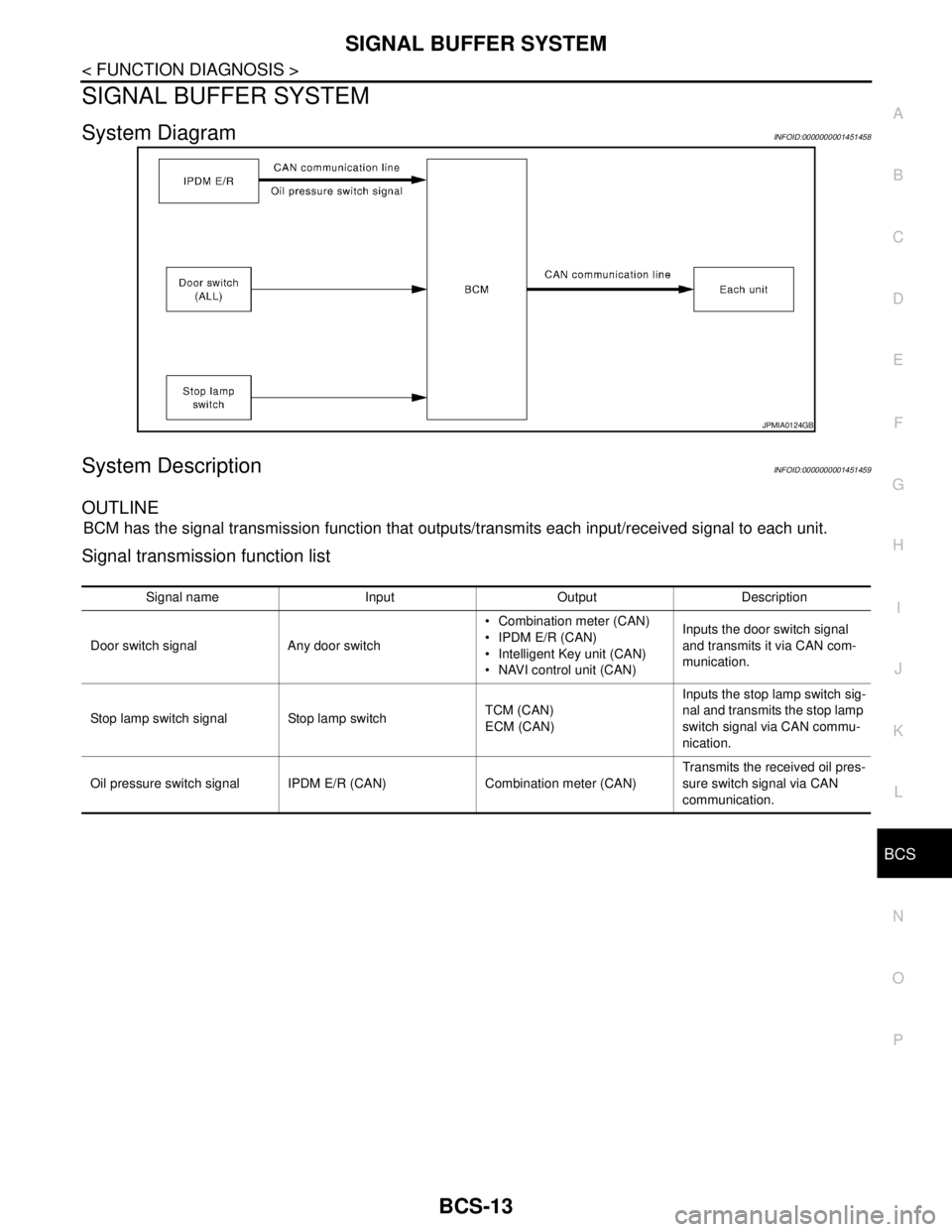
System DiagramINFOID:0000000001451458
System DescriptionINFOID:0000000001451459
OUTLINE
BCM has the signal transmission function that outputs/transmits each input/received signal to each unit.
Signal transmission function list
JPMIA0124GB
Signal name Input Output Description
Door switch signal Any door switch Combination meter (CAN)
IPDM E/R (CAN)
Intelligent Key unit (CAN)
NAVI control unit (CAN)Inputs the door switch signal
and transmits it via CAN com-
munication.
Stop lamp switch signal Stop lamp switchTCM (CAN)
ECM (CAN)Inputs the stop lamp switch sig-
nal and transmits the stop lamp
switch signal via CAN commu-
nication.
Oil pressure switch signal IPDM E/R (CAN) Combination meter (CAN)Transmits the received oil pres-
sure switch signal via CAN
communication.
Page 156 of 5883

BCS
DIAGNOSIS SYSTEM (BCM)
BCS-21
< FUNCTION DIAGNOSIS >
C
D
E
F
G
H
I
J
K
L B A
O
P N
ACTIVE TEST
WIPER
WIPER : CONSULT-III Function (BCM - WIPER)INFOID:0000000001451471
WORK SUPPORT
HI BEAM SW [ON/OFF]
Each switch status that BCM judges from the combination switch reading function H/L SW POS [ON/OFF]
LIGHT SW 1ST [ON/OFF]
PASSING SW [ON/OFF]
AUTO LIGHT SW [ON/OFF]
FR FOG SW [ON/OFF]
RR FOG SW [ON/OFF]
DOOR SW-DR [ON/OFF] The switch status input from front door switch (driver side)
ENGINE STATUS The engine status received from ECM with CAN communication
LIT-SEN FAIL [OK/NOTOK] The sensor status received from light & rain sensor with serial link
The serial link condition that BCM judges
AUT LIGHT SYS [ON/OFF] Auto light system status that BCM judges from the vehicle conditionMonitor item
[Unit]Description
Test item Operation Description
TAIL LAMPONTransmits the position light request signal to IPDM E/R with CAN com-
munication to turn the tail lamp ON.
OFF Stops the tail lamp request signal transmission.
HEAD LAMPHITransmits the high beam request signal with CAN communication to turn
the headlamp (HI).
LOTransmits the low beam request signal with CAN communication to turn
the headlamp (LO).
OFF Stops the high & low beam request signal transmission.
FR FOG LAMPONTransmits the front fog lights request signal to IPDM E/R with CAN com-
munication to turn the front fog lamp ON.
OFF Stops the front fog lights request signal transmission.
RR FOG LAMPON Outputs the voltage to turn the rear fog lamp ON.
Transmits the rear fog lamp status signal to the combination meter with
CAN communication to turn the rear fog lamp indicator lamp ON.
OFF Stops the voltage to turn the rear fog lamp OFF.
Stops the rear fog lamp status signal transmission.
DAYTIME RUNNING LIGHTONTransmits the day time running light request signal to IPDM E/R with
CAN communication to turn the each lamps ON.
OFF Stops the day time running light request signal transmission.
Work ItemSetting
ItemDescription
WIPER SPEED
SETTINGON
1With vehicle speed
(Front wiper intermittent time linked with the vehicle speed and wiper intermittent dial position)
OFFWithout vehicle speed
(Front wiper intermittent time linked with the wiper intermittent dial position)
RR WIP RVRS
SETON
2Change ON/OFF mode setting or rear wiper operation when gear is shifted to reverse
OFF
Page 163 of 5883
BCS-28
< COMPONENT DIAGNOSIS >
U1000 CAN COMM CIRCUIT
COMPONENT DIAGNOSIS
U1000 CAN COMM CIRCUIT
DescriptionINFOID:0000000001451482
Refer to LAN-33, "CAN Communication Signal Chart".
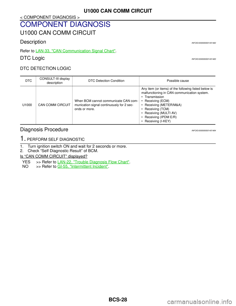
DTC LogicINFOID:0000000001451483
DTC DETECTION LOGIC
Diagnosis ProcedureINFOID:0000000001451484
1. PERFORM SELF DIAGNOSTIC
1. Turn ignition switch ON and wait for 2 seconds or more.
2. Check “Self Diagnostic Result” of BCM.
Is
“CAN COMM CIRCUIT” displayed?
YES >> Refer to LAN-22, "Trouble Diagnosis Flow Chart".
NO >> Refer to GI-55, "
Intermittent Incident".
DTCCONSULT-III display
descriptionDTC Detection Condition Possible cause
U1000 CAN COMM CIRCUITWhen BCM cannot communicate CAN com-
munication signal continuously for 2 sec-
onds or more.Any item (or items) of the following listed below is
malfunctioning in CAN communication system.
Transmission
Receiving (ECM)
Receiving (METER/M&A)
Receiving (TCM)
Receiving (MULTI AV)
Receiving (IPDM E/R)
Receiving (I-KEY)
Page 170 of 5883

BCS
BCM (BODY CONTROL MODULE)
BCS-35
< ECU DIAGNOSIS >
C
D
E
F
G
H
I
J
K
L B A
O
P N
ECU DIAGNOSIS
BCM (BODY CONTROL MODULE)
Reference ValueINFOID:0000000001451495
VALUES ON THE DIAGNOSIS TOOL
Monitor Item Condition Value/Status
AIR COND SWA/C switch OFF OFF
A/C switch ON ON
AUT LIGHT SYSOutside of the room is dark OFF
Outside of the room is bright ON
AUTO LIGHT SWLighting switch OFF OFF
Lighting switch AUTO ON
BACK DOOR SWBack door closed OFF
Back door opened ON
BATTERY VOLT
NOTE:
Diesel engine models
onlyIgnition switch ONApproximately the same as power
supply voltage
CDL LOCK SWDoor lock/unlock switch does not operate OFF
Press door lock/unlock switch to the LOCK side ON
CDL UNLOCK SWDoor lock/unlock switch does not operate OFF
Press door lock/unlock switch to the UNLOCK side ON
DOOR SW-ASPassenger door closed OFF
Passenger door opened ON
DOOR SW-DRDriver door closed OFF
Driver door opened ON
DOOR SW-RLRear LH door closed OFF
Rear LH door opened ON
DOOR SW-RRRear RH door closed OFF
Rear RH door opened ON
ELEC PWR CUT
NOTE:
Diesel engine models
onlyEngine runningFan switch ON (when engine coolant is
cool)
NOTE:
Depending on the ambient tempera-
ture, battery voltage, etc.OFF
The current status maintained with the
signal from ECM received.FREEZ
Fan switch OFF
Fan switch ON after engine warming
UP
NOTE:
Depending on the engine coolant
temperature, ambient temperature,
battery voltage, etc.INHBT
ENG COOLNT T
NOTE:
Diesel engine models
onlyEngine runningApproximately the same as engine
water temperature