blower NISSAN TIIDA 2007 Service Owner's Manual
[x] Cancel search | Manufacturer: NISSAN, Model Year: 2007, Model line: TIIDA, Model: NISSAN TIIDA 2007Pages: 5883, PDF Size: 78.95 MB
Page 3299 of 5883

REFRIGERATION SYSTEM
HA-17
< FUNCTION DIAGNOSIS >
C
D
E
F
G
H
J
K
L
MA
B
HA
N
O
P
7. Evaporator 8. Blower motor A. High-pressure gas
B. High-pressure liquid C. Low-pressure liquid D. Low-pressure gas
E. Suction port F. Discharge port G. Outside air
Page 3308 of 5883
HA-26
< ON-VEHICLE MAINTENANCE >
ELECTRICAL LEAK DETECTOR
2. Connect a suitable A/C manifold gauge set to the A/C service ports.
3. Check if the A/C refrigerant pressure is at least 345 kPa (3.45 bar, 3.52 kg/cm
2, 50 psi) above 16°C. If less
than specification, recover/evacuate and recharge the system with the specified amount of refrigerant.
NOTE:
At temperatures below 16°C, leaks may not be detected since the system may not reach 345 kPa (3.45
bar, 3.52 kg/cm
2, 50 psi).
4. Perform the leak test from the high-pressure side (compressor discharge a to evaporator inlet f) to the
low-pressure side (evaporator drain hose g to shaft seal k). Refer to HA-27, "
Component". Perform a leak
check for the following areas carefully. Clean the component to be checked and move the leak detected
probe completely around the connection/component.
Compressor
Check the fitting of high- and low-pressure flexible hoses, relief valve and shaft seal.
Condenser
Check the fitting of high-pressure flexible hose and pipe, refrigerant pressure sensor.
Liquid tank
Check the refrigerant connection.
Service valves
Check all around the service valves. Ensure service valve caps are secured on the service valves (to
prevent leaks).
NOTE:
After removing A/C manifold gauge set from service valves, wipe any residue from valves to prevent any
false readings by leak detector.
Cooling unit (Evaporator)
With engine OFF, turn blower fan on “High” for at least 15 seconds to dissipate any refrigerant trace in
the cooling unit. Wait a minimum of 10 minutes accumulation time (refer to the manufacturer’s recom-
mended procedure for actual wait time) before inserting the leak detector probe into the drain hose.
Keep the probe inserted for at least 10 seconds. Use caution not to contaminate the probe tip with water
or dirt that may be in the drain hose.
5. If a leak detector detects a leak, verify at least once by blowing compressed air into area of suspected
leak, then repeat check as outlined above.
6. Do not stop when one leak is found. Continue to check for additional leaks at all system components.
If no leaks are found, perform steps 7-10.
7. Start engine.
8. Set the heater A/C control as follows;
a. A/C switch: ON
b. Mode control dial position: VENT (Ventilation)
c. Intake door lever position: Recirculation
d. Max. cold temperature
e. Fan speed: High
9. Run engine at 1,500 rpm for at least 2 minutes.
10. Turn engine off and perform leak check again following steps 4
through 6 above.
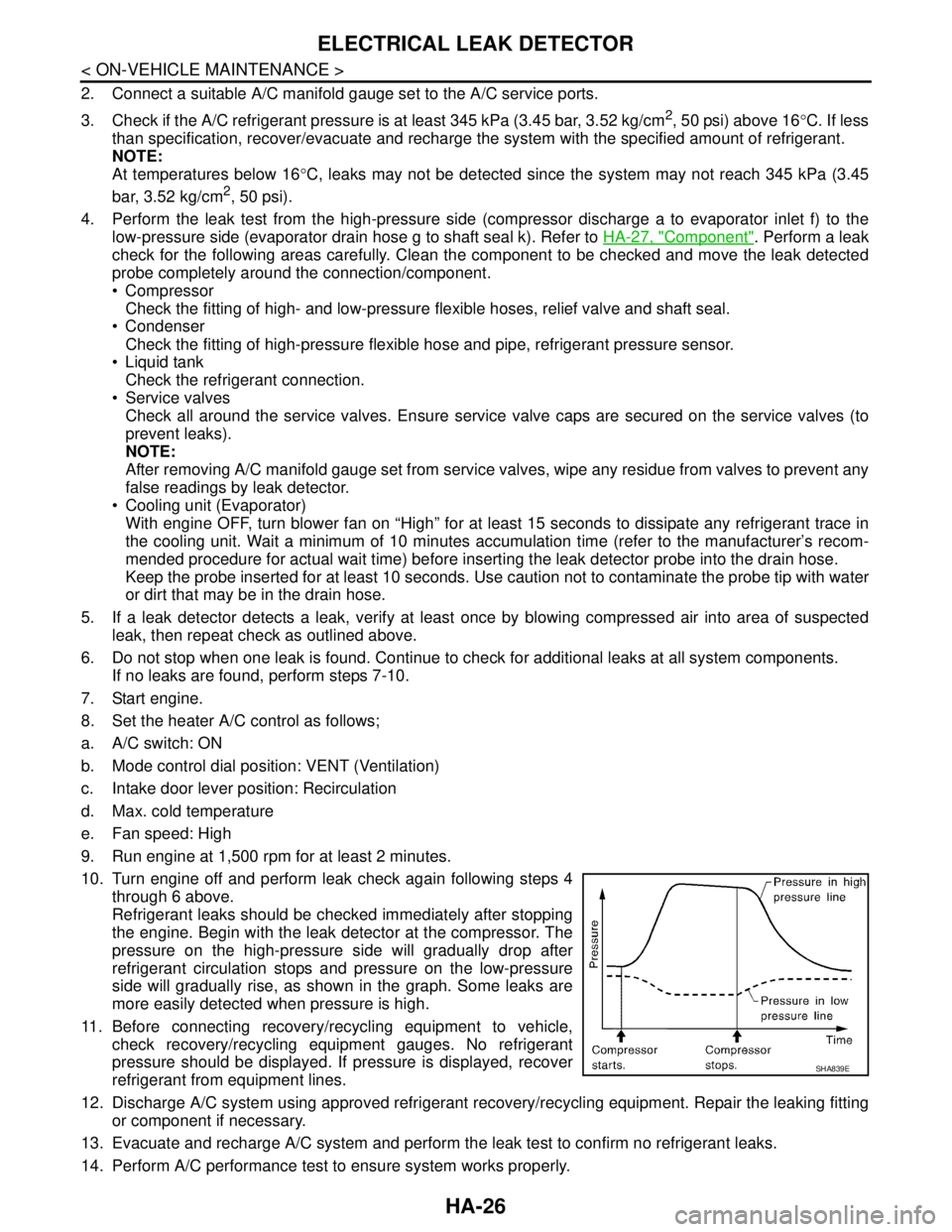
Refrigerant leaks should be checked immediately after stopping
the engine. Begin with the leak detector at the compressor. The
pressure on the high-pressure side will gradually drop after
refrigerant circulation stops and pressure on the low-pressure
side will gradually rise, as shown in the graph. Some leaks are
more easily detected when pressure is high.
11. Before connecting recovery/recycling equipment to vehicle,
check recovery/recycling equipment gauges. No refrigerant
pressure should be displayed. If pressure is displayed, recover
refrigerant from equipment lines.
12. Discharge A/C system using approved refrigerant recovery/recycling equipment. Repair the leaking fitting
or component if necessary.
13. Evacuate and recharge A/C system and perform the leak test to confirm no refrigerant leaks.
14. Perform A/C performance test to ensure system works properly.
SHA839E
Page 3334 of 5883

HAC-1
VENTILATION, HEATER & AIR CONDITIONER
C
D
E
F
G
H
J
K
L
M
SECTION HAC
A
B
HAC
N
O
P
CONTENTS
HEATER & AIR CONDITIONING CONTROL SYSTEM
MANUAL AIR CONDITIONER
BASIC INSPECTION ....................................
5
DIAGNOSIS AND REPAIR WORKFLOW ..........5
How to Perform Trouble Diagnosis For Quick and
Accurate Repair ........................................................
5
INSPECTION AND ADJUSTMENT .....................6
Operational Check ....................................................6
FUNCTION DIAGNOSIS ...............................8
FUNCTION INFORMATION ................................8
Component Part Location .........................................8
REFRIGERATION SYSTEM ..............................10
Refrigerant Cycle ....................................................10
Refrigerant System Protection ................................10
AIR CONDITIONER CONTROL .........................11
System Diagram ......................................................11
System Description .................................................11
Discharge Air Flow ..................................................11
Switches And Their Control Function ......................12
Component Description ...........................................13
CAN COMMUNICATION SYSTEM ....................14
System Description .................................................14
DIAGNOSIS SYSTEM (BCM) ............................15
CONSULT-III Function (BCM) .................................15
COMPONENT DIAGNOSIS .........................16
MODE DOOR .....................................................16
Mode Door Diagnostic Procedure ...........................16
AIR MIX DOOR ...................................................17
Air Mix Door Diagnostic Procedure .........................17
INTAKE DOOR ...................................................18
Intake Door Diagnostic Procedure ..........................18
BLOWER MOTOR ............................................19
Front Blower Motor Component Function Check ....19
Front Blower Motor Diagnosis Procedure ................19
MAGNET CLUTCH ...........................................23
System Description ..................................................23
Magnet Clutch Component Function Check ............23
Magnet Clutch Diagnosis Procedure .......................24
INTAKE SENSOR .............................................30
Component Inspection .............................................30
Intake Sensor Diagnosis Procedure ........................30
Intake Sensor Component Inspection .....................31
PTC HEATER CONTROL SYSTEM .................33
PTC HEATER (300 WATT) ........................................33
PTC HEATER (300 WATT) : PTC Heater System
Description ...............................................................
33
PTC HEATER (300 WATT) : PTC Heater Compo-
nent Description .......................................................
34
PTC HEATER (300 WATT) : PTC Heater (300
Watt) Diagnosis Procedure ......................................
35
PTC HEATER (300 WATT) : PTC Heater (300
Watt) Component Inspection ...................................
41
PTC HEATER (1500 WATT) ......................................43
PTC HEATER (1500 WATT) : System Description ....43
PTC HEATER (1500 WATT) : Component De-
scription ...................................................................
44
PTC HEATER (1500 WATT) : PTC Heater (1500
Watt) Diagnosis Procedure ......................................
45
PTC HEATER (1500 WATT) : PTC Heater (1500
Watt) Component Inspection ...................................
50
ECU DIAGNOSIS .........................................53
AIR CONDITIONER CONTROL ........................53
Reference Value ......................................................53
Wiring Diagram - Heater Control (without A/C) - .....54
Wiring Diagram - Air Conditioner Control - ..............56
Page 3335 of 5883

HAC-2
PTC HEATER CONTROL SYSTEM ..................63
PTC HEATER (300 WATT) .......................................63
PTC HEATER (300 WATT) : Wiring Diagram -
PTC Heater (300 Watt) - .........................................
63
PTC HEATER (1500 WATT) .....................................67
PTC HEATER (1500 WATT) : Wiring Diagram -
PTC Heater (1500 Watt) - .......................................
68
SYMPTOM DIAGNOSIS .............................72
AIR CONDITIONER CONTROL ........................72
Symptom Matrix Chart ..........................................72
INSUFFICIENT COOLING .................................73
Component Function Check ...................................73
Performance Test Diagnoses .................................74
Performance Chart .................................................75
Test Reading ..........................................................76
Trouble Diagnoses for Unusual Pressure ...............77
INSUFFICIENT HEATING .................................81
Component Function Check ...................................81
NOISE ................................................................83
Component Function Check ...................................83
PRECAUTION .............................................84
PRECAUTIONS .................................................84
Precaution for Supplemental Restraint System
(SRS) "AIR BAG" and "SEAT BELT PRE-TEN-
SIONER" .................................................................
84
Precaution for Procedures Without Cowl Top Cov-
er ............................................................................
84
Working with HFC-134a (R-134a) ..........................84
Precaution for Service Equipment ..........................85
AUTO AIR CONDITIONER (W/O NAVI)
BASIC INSPECTION ...................................
86
DIAGNOSIS AND REPAIR WORKFLOW .........86
How to Perform Trouble Diagnosis For Quick And
Accurate Repair ......................................................
86
INSPECTION AND ADJUSTMENT ...................87
Operational Check ..................................................87
FUNCTION DIAGNOSIS .............................89
FUNCTION INFORMATION ..............................89
Component Part Location .......................................89
REFRIGERATION SYSTEM ..............................91
Refrigerant Cycle ....................................................91
Refrigerant System Protection ................................91
AUTOMATIC AIR CONDITIONER SYSTEM .....92
Control System Diagram ........................................92
Control System Description ....................................92
Discharge Air Flow .................................................94
Switches And Their Control Function ......................95
CAN COMMUNICATION SYSTEM ...................96
System Description .................................................96
DIAGNOSIS SYSTEM (BCM) ............................97
CONSULT-III Function (BCM) ................................97
SELF-DIAGNOSIS FUNCTION .........................98
Front Air Control Self-Diagnosis .............................98
A/C System Self-Diagnosis Code Chart ...............104
COMPONENT DIAGNOSIS ......................106
MODE DOOR MOTOR .....................................106
System Description ...............................................106
Mode Door Motor Component Function Check ....107
Mode Door Motor Diagnosis Procedure ................109
AIR MIX DOOR MOTOR ..................................110
System Description ...............................................110
Air Mix Door Motor Component Function Check ..111
Air Mix Door Motor Diagnosis Procedure ..............112
INTAKE DOOR MOTOR ...................................114
System Description ...............................................114
Intake Door Motor Component Function Check ....115
Intake Door Motor Diagnosis Procedure ...............116
BLOWER MOTOR CONTROL SYSTEM .........118
System Description ...............................................118
Front Blower Motor Component Function Check ..119
Front Blower Motor Diagnosis Procedure .............120
Front Blower Motor Component Inspection ..........123
MAGNET CLUTCH ...........................................124
System Description ...............................................124
Magnet Clutch Component Function Check .........124
Magnet Clutch Diagnosis Procedure ....................125
AMBIENT SENSOR ..........................................130
Component Description ........................................130
Ambient Sensor Diagnosis Procedure ..................130
Ambient Sensor Component Inspection ...............131
IN-VEHICLE SENSOR ......................................133
Component Description ........................................133
In-Vehicle Sensor Diagnosis Procedure ...............133
In-Vehicle Sensor Component Inspection .............135
SUNLOAD SENSOR ........................................136
System Description ...............................................136
Sunload Sensor Diagnosis Procedure ..................136
Sunload Component Inspection ............................137
INTAKE SENSOR .............................................139
Component Inspection ..........................................139
Intake Sensor Diagnosis Procedure .....................139
Intake Sensor Component Inspection ...................140
PTC HEATER CONTROL SYSTEM .................142
Page 3337 of 5883

HAC-4
INTAKE DOOR MOTOR ..................................228
System Description ................................................228
Intake Door Motor Component Function Check ....229
Intake Door Motor Diagnosis Procedure ...............230
BLOWER MOTOR CONTROL SYSTEM ........232
System Description ................................................232
Front Blower Motor Component Function Check ...233
Front Blower Motor Diagnosis Procedure ..............234
Front Blower Motor Component Inspection ...........236
MAGNET CLUTCH ..........................................238
System Description ................................................238
Magnet Clutch Component Function Check ..........238
Magnet Clutch Diagnosis Procedure .....................239
AMBIENT SENSOR .........................................244
Component Description .........................................244
Ambient Sensor Diagnosis Procedure ...................244
Ambient Sensor Component Inspection ................245
IN-VEHICLE SENSOR .....................................247
Component Description .........................................247
In-Vehicle Sensor Diagnosis Procedure ................247
In-Vehicle Sensor Component Inspection .............249
SUNLOAD SENSOR .......................................250
Component Description .........................................250
Sunload Sensor Diagnosis Procedure ...................250
Sunload Sensor Component Inspection ................251
INTAKE SENSOR ............................................253
System Description ................................................253
Intake Sensor Diagnosis Procedure ......................253
Intake Sensor Component Inspection ...................254
PTC HEATER CONTROL SYSTEM ................256
PTC HEATER (300 WATT) ......................................256
PTC HEATER (300 WATT) : PTC Heater System
Description .............................................................
256
PTC HEATER (300 WATT) : PTC Heater Compo-
nent Description .....................................................
257
PTC HEATER (300 WATT) : PTC Heater (300
Watt) Diagnosis Procedure ....................................
258
PTC HEATER (300 WATT) : PTC Heater (300
Watt) Component Inspection .................................
265
PTC HEATER (1500 WATT) ....................................267
PTC HEATER (1500 WATT) : System Description ..267
PTC HEATER (1500 WATT) : Component De-
scription .................................................................
268
PTC HEATER (1500 WATT) : PTC Heater (1500
Watt) Diagnosis Procedure ....................................
269
PTC HEATER (1500 WATT) : PTC Heater (1500
Watt) Component Inspection .................................
274
POWER SUPPLY AND GROUND CIRCUIT
FOR CONTROLLER .........................................
277
Component Description ........................................277
A/C Auto Amp. Component Function Check .........277
A/C Auto Amp Power and Ground Diagnosis Pro-
cedure ...................................................................
278
ECU DIAGNOSIS ......................................279
AIR CONDITIONER CONTROL .......................279
Front Air Control Terminals Reference Values .....279
Wiring Diagram - Air Conditioner Control - ...........281
PTC HEATER CONTROL SYSTEM .................289
PTC HEATER (300 WATT) .....................................289
PTC HEATER (300 WATT) : Wiring Diagram -
PTC Heater (300 Watt) - .......................................
289
PTC HEATER (1500 WATT) ...................................293
PTC HEATER (1500 WATT) : Wiring Diagram -
PTC Heater (1500 Watt) - .....................................
294
SYMPTOM DIAGNOSIS ...........................298
AIR CONDITIONER CONTROL .......................298
Symptom Matrix Chart .........................................298
INSUFFICIENT COOLING ................................299
Component Function Check .................................299
Performance Test Diagnoses ...............................300
Performance Chart ................................................302
Test Reading .........................................................303
Trouble Diagnoses for Unusual Pressure .............303
INSUFFICIENT HEATING ................................307
Component Function Check .................................307
NOISE ...............................................................309
Component Function Check .................................309
SELF-DIAGNOSIS CANNOT BE PER-
FORMED ...........................................................
311
Self-Diagnosis .......................................................311
MEMORY FUNCTION DOES NOT OPERATE ..312
Memory Function Check .......................................312
PRECAUTION ...........................................313
PRECAUTIONS ................................................313
Precaution for Supplemental Restraint System
(SRS) "AIR BAG" and "SEAT BELT PRE-TEN-
SIONER" ...............................................................
313
Precaution for Procedures Without Cowl Top Cov-
er ...........................................................................
313
Working with HFC-134a (R-134a) .........................313
Precaution for Service Equipment ........................314
Page 3339 of 5883
![NISSAN TIIDA 2007 Service Owners Manual HAC-6
< BASIC INSPECTION >[MANUAL AIR CONDITIONER]
INSPECTION AND ADJUSTMENT
INSPECTION AND ADJUSTMENT
Operational CheckINFOID:0000000001203052
The purpose of the operational check is to confirm that](/img/5/57395/w960_57395-3338.png "NISSAN TIIDA 2007 Service Owners Manual HAC-6
< BASIC INSPECTION >[MANUAL AIR CONDITIONER]
INSPECTION AND ADJUSTMENT
INSPECTION AND ADJUSTMENT
Operational CheckINFOID:0000000001203052
The purpose of the operational check is to confirm that")
HAC-6
< BASIC INSPECTION >[MANUAL AIR CONDITIONER]
INSPECTION AND ADJUSTMENT
INSPECTION AND ADJUSTMENT
Operational CheckINFOID:0000000001203052
The purpose of the operational check is to confirm that the system operates properly.
CHECKING BLOWER
1. Turn blower control dial clockwise to "1" position. Blower should operate on low speed.
2. Turn blower control dial clockwise to "2" position, and continue checking blower speed until all speeds are
checked.
3. Leave blower on Maximum speed.
If NG, go to trouble diagnosis procedure for xxx BLOWER MOTOR CIR HAC-19, "
Front Blower Motor Diagno-
sis Procedure".
If OK, continue the check.
CHECKING DISCHARGE AIR
1. Turn mode door control dial to each position.
2. Confirm that discharge air comes out according to the air distribution table. Refer to XXXX DISCHARGE
AIR FLOW.
If NG, go to trouble diagnosis procedure for HAC-16, "
Mode Door Diagnostic Procedure".
If OK, continue the check.
CHECKING RECIRCULATION
1. Set intake door lever to REC position.
2. Operate intake door lever to FRE position.
3. Listen for intake door position change (you should hear blower sound change slightly).
If NG, go to trouble diagnosis procedure for XXXX INTAKE DOOR.
If OK, continue the check.
CHECKING TEMPERATURE DECREASE
1. Turn temperature control dial counterclockwise to full cold position.
2. Check for cold air at discharge air outlets.
If NG, go to trouble diagnosis procedure for XXXX INSUFFICIENT COOLING.
If OK, continue the check.
CHECKING TEMPERATURE INCREASE
1. Turn temperature control dial clockwise to full hot position.
2. Check for hot air at discharge air outlets.
If NG, go to trouble diagnosis procedure for XXXX INSUFFICIENT HEATING.
If OK, continue the check.
CHECKING A/C SWITCH (IF EQUIPPED)
1. Turn fan control dial to the desired (1 to 4 speed) position.
2. Press A/C switch.
3. A/C switch indicator will turn ON.
• Confirm that the compressor clutch engages (sound or visual inspection).
If NG, go to trouble diagnosis procedure for XXXX MAG CLUTCH CIR.
If OK, continue the check.
CHECKING DEFROST A/C SWITCH (IF EQUIPPED)
1. Turn fan control dial to the desired (1 to 4 speed) position.
2. Turn mode dial to ( ) DEF.
3. Confirm that the compressor clutch engages (sound or visual inspection). Conditions : Engine running at normal operating temperature
Page 3342 of 5883
![NISSAN TIIDA 2007 Service Owners Manual FUNCTION INFORMATION
HAC-9
< FUNCTION DIAGNOSIS >[MANUAL AIR CONDITIONER]
C
D
E
F
G
H
J
K
L
MA
B
HAC
N
O
P
1. Front air control M33, M49 2. Fuse Block (J/B) 3. Blower relay J-1
4. Front blower motor r](/img/5/57395/w960_57395-3341.png "NISSAN TIIDA 2007 Service Owners Manual FUNCTION INFORMATION
HAC-9
< FUNCTION DIAGNOSIS >[MANUAL AIR CONDITIONER]
C
D
E
F
G
H
J
K
L
MA
B
HAC
N
O
P
1. Front air control M33, M49 2. Fuse Block (J/B) 3. Blower relay J-1
4. Front blower motor r")
FUNCTION INFORMATION
HAC-9
< FUNCTION DIAGNOSIS >[MANUAL AIR CONDITIONER]
C
D
E
F
G
H
J
K
L
MA
B
HAC
N
O
P
1. Front air control M33, M49 2. Fuse Block (J/B) 3. Blower relay J-1
4. Front blower motor resistor M95 5. Intake sensor M42 6. Front blower motor M62
7. Defrost A/C switch M49
WJIA2258E
Page 3344 of 5883
![NISSAN TIIDA 2007 Service Owners Manual AIR CONDITIONER CONTROL
HAC-11
< FUNCTION DIAGNOSIS >[MANUAL AIR CONDITIONER]
C
D
E
F
G
H
J
K
L
MA
B
HAC
N
O
P
AIR CONDITIONER CONTROL
System DiagramINFOID:0000000001203055
System DescriptionINFOID:00](/img/5/57395/w960_57395-3343.png "NISSAN TIIDA 2007 Service Owners Manual AIR CONDITIONER CONTROL
HAC-11
< FUNCTION DIAGNOSIS >[MANUAL AIR CONDITIONER]
C
D
E
F
G
H
J
K
L
MA
B
HAC
N
O
P
AIR CONDITIONER CONTROL
System DiagramINFOID:0000000001203055
System DescriptionINFOID:00")
AIR CONDITIONER CONTROL
HAC-11
< FUNCTION DIAGNOSIS >[MANUAL AIR CONDITIONER]
C
D
E
F
G
H
J
K
L
MA
B
HAC
N
O
P
AIR CONDITIONER CONTROL
System DiagramINFOID:0000000001203055
System DescriptionINFOID:0000000001203056
BLOWER CONTROL DIAL
This dial turns the fan ON and OFF, and controls fan speed.
TEMPERATURE CONTROL DIAL
This dial allows you to adjust the temperature of the discharge air.
MODE DOOR CONTROL DIAL
This dial controls the outlet air flow.
INTAKE DOOR LEVER
Recirculation (REC) position: Interior air is recirculated inside the vehicle.
Fresh (FRE) position: Outside air is drawn into the passenger compartment.
REAR WINDOW DEFOGGER SWITCH
When illumination is ON, rear window is defogged.
A/C SWITCH (IF EQUIPPED)
The A/C switch controls the air conditioner system. When the switch is depressed with the fan ON, the com-
pressor will turn ON. The indicator lamp also illuminates.
Discharge Air FlowINFOID:0000000001547285
1. Intake door lever 2. Mode door control dial 3. Rear window defogger switch
4. Blower control dial 5. A/C switch (if equipped) 6. Temperature control dial
WJIA2189E
Page 3348 of 5883
![NISSAN TIIDA 2007 Service Owners Manual DIAGNOSIS SYSTEM (BCM)
HAC-15
< FUNCTION DIAGNOSIS >[MANUAL AIR CONDITIONER]
C
D
E
F
G
H
J
K
L
MA
B
HAC
N
O
P
DIAGNOSIS SYSTEM (BCM)
CONSULT-III Function (BCM)INFOID:0000000001203060
CONSULT-III can d](/img/5/57395/w960_57395-3347.png "NISSAN TIIDA 2007 Service Owners Manual DIAGNOSIS SYSTEM (BCM)
HAC-15
< FUNCTION DIAGNOSIS >[MANUAL AIR CONDITIONER]
C
D
E
F
G
H
J
K
L
MA
B
HAC
N
O
P
DIAGNOSIS SYSTEM (BCM)
CONSULT-III Function (BCM)INFOID:0000000001203060
CONSULT-III can d")
DIAGNOSIS SYSTEM (BCM)
HAC-15
< FUNCTION DIAGNOSIS >[MANUAL AIR CONDITIONER]
C
D
E
F
G
H
J
K
L
MA
B
HAC
N
O
P
DIAGNOSIS SYSTEM (BCM)
CONSULT-III Function (BCM)INFOID:0000000001203060
CONSULT-III can display each diagnostic item using the diagnostic test modes shown following.
DATA MONITOR
Display Item List
BCM diagnostic
test itemDiagnostic mode Description
Inspection by partWORK SUPPORTSupports inspections and adjustments. Commands are transmitted to the BCM for
setting the status suitable for required operation, input/output signals are received
from the BCM and received data is displayed.
DATA MONITOR Displays BCM input/output data in real time.
ACTIVE TEST Operation of electrical loads can be checked by sending drive signal to them.
SELF-DIAG RESULTS Displays BCM self-diagnosis results.
CAN DIAG SUPPORT MNTR The result of transmit/receive diagnosis of CAN communication can be read.
ECU PART NUMBER BCM part number can be read.
CONFIGURATION Performs BCM configuration read/write functions.
Monitor item name
“operation or unit”Contents
IGN ON SW “ON/OFF”Displays “IGN Position (ON)/OFF, ACC Position (OFF)” status as judged from ignition switch signal
through the CAN communication.
FAN ON SIG “ON/OFF”Displays “FAN (ON)/FAN (OFF)” status as judged from blower fan motor switch signal through CAN
communication.
AIR COND SW “ON/OFF”Displays “COMP (ON)/COMP (OFF)” status as judged from air conditioner switch signal through the
CAN communication.
Page 3351 of 5883
![NISSAN TIIDA 2007 Service Owners Manual HAC-18
< COMPONENT DIAGNOSIS >[MANUAL AIR CONDITIONER]
INTAKE DOOR
INTAKE DOOR
Intake Door Diagnostic ProcedureINFOID:0000000001547065
SYMPTOM:
Intake door does not change.
INSPECTION FLOW
1.CONFIRM](/img/5/57395/w960_57395-3350.png "NISSAN TIIDA 2007 Service Owners Manual HAC-18
< COMPONENT DIAGNOSIS >[MANUAL AIR CONDITIONER]
INTAKE DOOR
INTAKE DOOR
Intake Door Diagnostic ProcedureINFOID:0000000001547065
SYMPTOM:
Intake door does not change.
INSPECTION FLOW
1.CONFIRM")
HAC-18
< COMPONENT DIAGNOSIS >[MANUAL AIR CONDITIONER]
INTAKE DOOR
INTAKE DOOR
Intake Door Diagnostic ProcedureINFOID:0000000001547065
SYMPTOM:
Intake door does not change.
INSPECTION FLOW
1.CONFIRM SYMPTOM BY PERFORMING OPERATIONAL CHECK - REC ( )
1. Slide the intake door lever to the REC ( ) position.
2. Turn the blower motor to maximum speed.
3. Slide the intake door lever to the FRE position.
4. Listen for intake door position change (you should hear blower sound change slightly).
Can a symptom be duplicated?
YES >> GO TO 3.
NO >> GO TO 2.
2.PERFORM COMPLETE OPERATIONAL CHECK
Perform a complete operational check and check for any symptoms. Refer to HAC-6, "
Operational Check" .
Can a symptom be duplicated?
YES >> Refer to HAC-5, "How to Perform Trouble Diagnosis For Quick and Accurate Repair" .
NO >> System OK.
3.CHECK FOR SERVICE BULLETINS
Check for any service bulletins.
>> GO TO 4.
4.CHECK INTAKE DOOR CONTROL LINKAGE
Check intake door control linkage mechanism for smooth operation.
OK or NG
OK >> If the symptom still exists, perform a complete operational check. Refer to HAC-6, "Operational
Check" . If other symptoms exist, refer to HAC-5, "How to Perform Trouble Diagnosis For Quick
and Accurate Repair" .
NG >> Repair or adjust control linkage. Refer to XXXX INTAKE DOOR CABLE ADJUSTMENT .