mirror NISSAN TIIDA 2007 Service Repair Manual
[x] Cancel search | Manufacturer: NISSAN, Model Year: 2007, Model line: TIIDA, Model: NISSAN TIIDA 2007Pages: 5883, PDF Size: 78.95 MB
Page 1 of 5883
MODEL C11 SERIES
2007 NISSAN EUROPE S.A.S.
All rights reserved. No part of this Electronic Service Manual may be reproduced or stored in a retrieval system, or transmitted in any form,
or by any means, electronic, mechanical, photocopying, recording or otherwise, without the prior written permission of Nissan Europe
S.A.S., Paris, France.
A GENERAL INFORMATION
B ENGINE
D TRANSMISSION& DRIVELINE
E SUSPENSION F BRAKES
G STEERING H RESTRAINTS
I VENTILATION, HEATER & AIR CONDITIONER
J BODY INTERIOR
K BODY EXTERIOR, DOOR, ROOF & VEHICLE SECURITY
L DRIVER CONTROLS
M ELECTRICAL & POWER CONTROL
N DRIVER INFORMATION & MULTIMEDIA
O CRUISE CONTROL P MAINTENANCEGI General Information
EM Engine Mechanical
LU Engine Lubrication System
CO Engine Cooling System
EC Engine Control System
FL Fuel System
EX Exhaust System
STR Starting System
ACC Accelerator Control System
CL Clutch
TM Transaxle & Transmission
FAX Front Axle
RAX Rear Axle
FSU Front Suspension
RSU Rear Suspension
WT Road Wheels & Tires
BR Brake System
PB Parking Brake System
BRC Brake Control System
ST Steering System
STC Steering Control System
SB Seat Belt
SR SRS Airbag
SRC SRS Airbag Control System
VTL Ventilation System
HA Heater & Air Conditioning System
HAC Heater & Air Conditioning Control System
INT Interior
IP Instrument Panel
SE Seat
DLK Door & Lock
SEC Security Control System
GW Glass & Window System
PWC Power Window Control System
RF Roof
EXT Exterior
MIR Mirrors
EXL Exterior Lighting System
INL Interior Lighting System
WW Wiper & Washer
DEF Defogger
HRN Horn
PWO Power Outlet
BCS Body Control System
LAN LAN System
PCS Power Control System
CHG Charging System
PG Power Supply, Ground & Circuit Elements
MWI Meter, Warning Lanp & Indicator
WCS Warning Chime System
AV Audio, Visual & Navigation System
CCS Cruise Control System Maintenance
MA Maintenance
QUICK REFERENCE INDEX
A
B
C
D
E
F
G
H
I
J
K
L
M
N
O
P
M
Publication Number:
SM7E00-1C11E0E
Page 552 of 5883
DEF-1
DRIVER CONTROLS
C
D
E
F
G
H
I
J
K
M
SECTION DEF
A
B
DEF
N
O
P
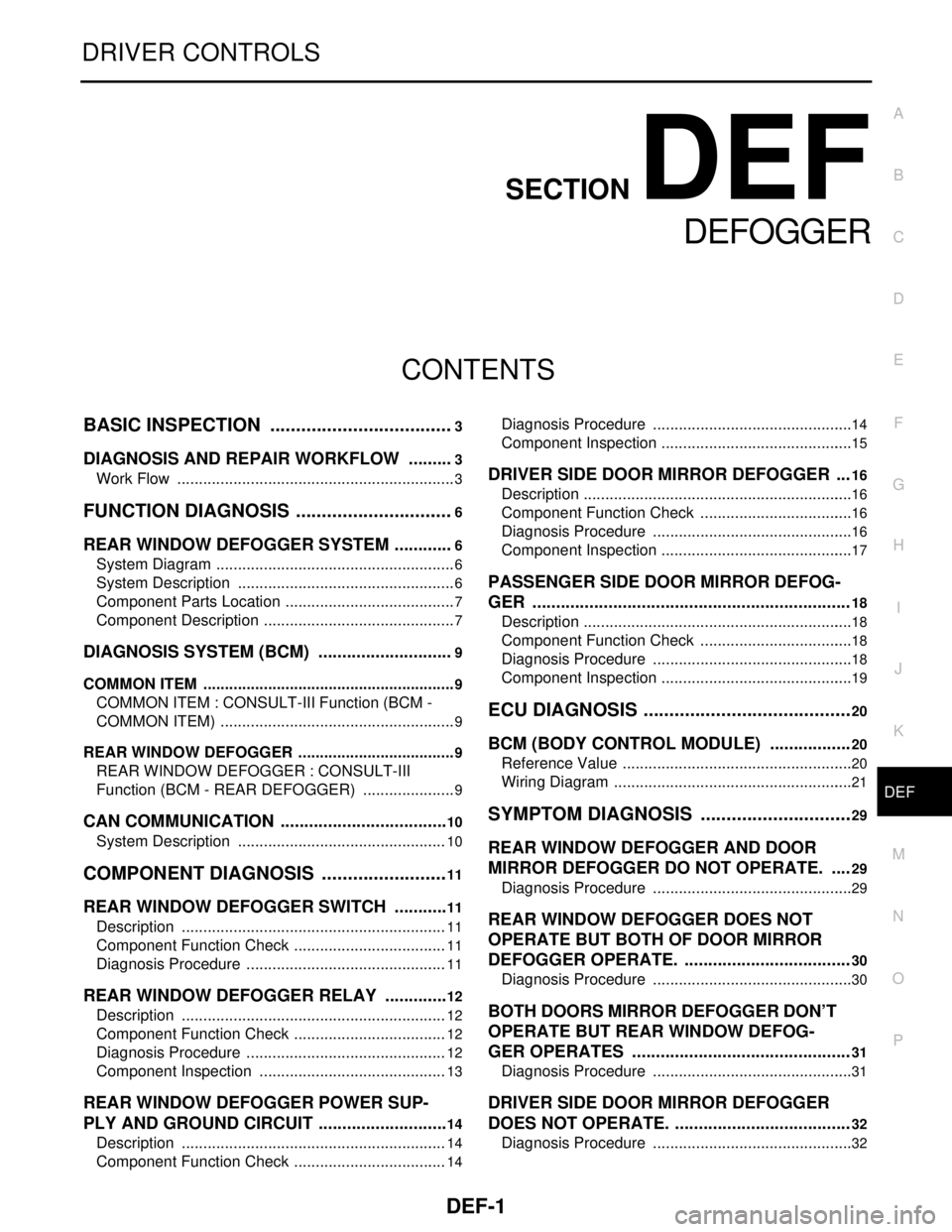
CONTENTS
DEFOGGER
BASIC INSPECTION ....................................3
DIAGNOSIS AND REPAIR WORKFLOW ..........3
Work Flow .................................................................3
FUNCTION DIAGNOSIS ...............................6
REAR WINDOW DEFOGGER SYSTEM .............6
System Diagram ........................................................6
System Description ...................................................6
Component Parts Location ........................................7
Component Description .............................................7
DIAGNOSIS SYSTEM (BCM) .............................9
COMMON ITEM ...........................................................9
COMMON ITEM : CONSULT-III Function (BCM -
COMMON ITEM) .......................................................
9
REAR WINDOW DEFOGGER .....................................9
REAR WINDOW DEFOGGER : CONSULT-III
Function (BCM - REAR DEFOGGER) ......................
9
CAN COMMUNICATION ....................................10
System Description .................................................10
COMPONENT DIAGNOSIS .........................11
REAR WINDOW DEFOGGER SWITCH ............11
Description ..............................................................11
Component Function Check ....................................11
Diagnosis Procedure ...............................................11
REAR WINDOW DEFOGGER RELAY ..............12
Description ..............................................................12
Component Function Check ....................................12
Diagnosis Procedure ...............................................12
Component Inspection ............................................13
REAR WINDOW DEFOGGER POWER SUP-
PLY AND GROUND CIRCUIT ............................
14
Description ..............................................................14
Component Function Check ....................................14
Diagnosis Procedure ...............................................14
Component Inspection .............................................15
DRIVER SIDE DOOR MIRROR DEFOGGER ...16
Description ...............................................................16
Component Function Check ....................................16
Diagnosis Procedure ...............................................16
Component Inspection .............................................17
PASSENGER SIDE DOOR MIRROR DEFOG-
GER ...................................................................
18
Description ...............................................................18
Component Function Check ....................................18
Diagnosis Procedure ...............................................18
Component Inspection .............................................19
ECU DIAGNOSIS .........................................20
BCM (BODY CONTROL MODULE) .................20
Reference Value ......................................................20
Wiring Diagram ........................................................21
SYMPTOM DIAGNOSIS ..............................29
REAR WINDOW DEFOGGER AND DOOR
MIRROR DEFOGGER DO NOT OPERATE. ....
29
Diagnosis Procedure ...............................................29
REAR WINDOW DEFOGGER DOES NOT
OPERATE BUT BOTH OF DOOR MIRROR
DEFOGGER OPERATE. ...................................
30
Diagnosis Procedure ...............................................30
BOTH DOORS MIRROR DEFOGGER DON’T
OPERATE BUT REAR WINDOW DEFOG-
GER OPERATES ..............................................
31
Diagnosis Procedure ...............................................31
DRIVER SIDE DOOR MIRROR DEFOGGER
DOES NOT OPERATE. .....................................
32
Diagnosis Procedure ...............................................32
Page 553 of 5883

DEF-2
PASSENGER SIDE DOOR MIRROR DEFOG-
GER DOES NOT OPERATE. ............................
33
Diagnosis Procedure ..............................................33
REAR WINDOW DEFOGGER SWITCH DOES
NOT LIGHT, BUT REAR WINDOW DEFOG-
GER OPERATES ...............................................
34
Diagnosis Procedure ..............................................34
PRECAUTION .............................................35
PRECAUTIONS .................................................35
Supplemental Restraint System (SRS) "AIR BAG"
and "SEAT BELT PRE-TENSIONER" ....................
35
ON-VEHICLE REPAIR ...............................36
FILAMENT .........................................................36
Inspection and Repair .............................................36
CONDENSER ....................................................38
Exploded View ........................................................38
Removal and Installation .........................................38
Page 557 of 5883
DEF-6
< FUNCTION DIAGNOSIS >
REAR WINDOW DEFOGGER SYSTEM
FUNCTION DIAGNOSIS
REAR WINDOW DEFOGGER SYSTEM
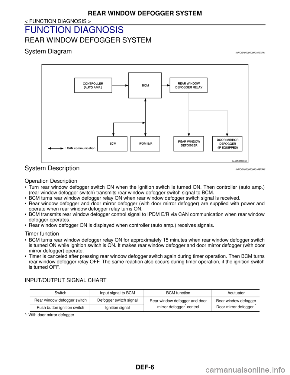
System DiagramINFOID:0000000001697541
System DescriptionINFOID:0000000001697542
Operation Description
Turn rear window defogger switch ON when the ignition switch is turned ON. Then controller (auto amp.)
(rear window defogger switch) transmits rear window defogger switch signal to BCM.
BCM turns rear window defogger relay ON when rear window defogger switch signal is received.
Rear window defogger and door mirror defogger (with door mirror defogger) are supplied with power and
operate when rear window defogger relay turns ON.
BCM transmits rear window defogger control signal to IPDM E/R via CAN communication when rear window
defogger operates.
Rear window defogger ON is displayed when controller (auto amp.) receives signals.
Timer function
BCM turns rear window defogger relay ON for approximately 15 minutes when rear window defogger switch
is turned ON while ignition switch is ON. It makes rear window defogger and door mirror defogger (with door
mirror defogger) operate.
Timer is canceled after pressing rear window defogger switch again during timer operation. Then BCM turns
rear window defogger relay OFF. The same reaction also occurs during timer operation, if the ignition switch
is turned OFF.
INPUT/OUTPUT SIGNAL CHART
*: With door mirror defogger
ALLIA0183GB
Switch Input signal to BCM BCM function Acutuator
Rear window defogger switch Defogger switch signal
Rear window defogger and door
mirror defogger
* controlRear window defogger
Door mirror defogger *Push button ignition switch Ignition signal
Page 558 of 5883
REAR WINDOW DEFOGGER SYSTEM
DEF-7
< FUNCTION DIAGNOSIS >
C
D
E
F
G
H
I
J
K
MA
B
DEF
N
O
P
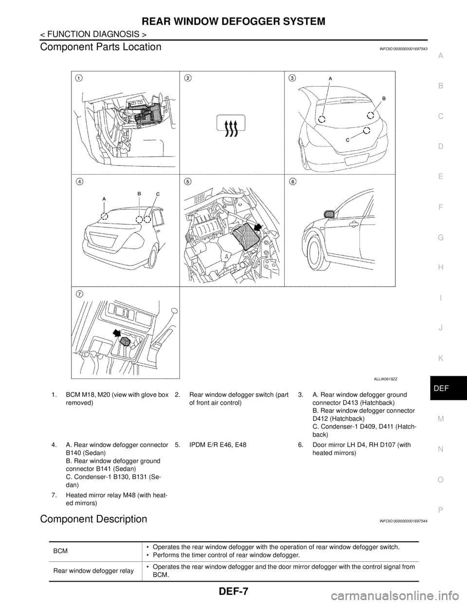
Component Parts LocationINFOID:0000000001697543
Component DescriptionINFOID:0000000001697544
ALLIA0619ZZ
1. BCM M18, M20 (view with glove box
removed)2. Rear window defogger switch (part
of front air control)3. A. Rear window defogger ground
connector D413 (Hatchback)
B. Rear window defogger connector
D412 (Hatchback)
C. Condenser-1 D409, D411 (Hatch-
back)
4. A. Rear window defogger connector
B140 (Sedan)
B. Rear window defogger ground
connector B141 (Sedan)
C. Condenser-1 B130, B131 (Se-
dan)5. IPDM E/R E46, E48 6. Door mirror LH D4, RH D107 (with
heated mirrors)
7. Heated mirror relay M48 (with heat-
ed mirrors)
BCM Operates the rear window defogger with the operation of rear window defogger switch.
Performs the timer control of rear window defogger.
Rear window defogger relay Operates the rear window defogger and the door mirror defogger with the control signal from
BCM.
Page 559 of 5883

DEF-8
< FUNCTION DIAGNOSIS >
REAR WINDOW DEFOGGER SYSTEM
*: With door mirror defoggerFront air control (rear window
defogger switch) The rear window defogger switch is turned ON.
Turns the indicator lamp ON when detecting the operation of rear window defogger.
Rear window defogger Heats the heating wire with the power supply from the rear window defogger relay to prevent
the rear window from fogging up.
Door mirror defogger
* Heats the heating wire with the power supply from the rear window defogger relay to prevent
the door mirror from fogging up.
Page 567 of 5883
DEF-16
< COMPONENT DIAGNOSIS >
DRIVER SIDE DOOR MIRROR DEFOGGER
DRIVER SIDE DOOR MIRROR DEFOGGER
DescriptionINFOID:0000000001697559
Heats the heating wire with the power supply from the rear window defogger relay to prevent the door mirror
from fogging up.
Component Function CheckINFOID:0000000001697560
1. CHECK DOOR MIRROR DEFOGGER LH
Check that heating wire of door mirror defogger LH is heated when turning the rear window defogger switch
ON.
Is the inspection result normal?
YES >> Door mirror defogger is OK.
NO >> Refer to DEF-16, "
Diagnosis Procedure".
Diagnosis ProcedureINFOID:0000000001697561
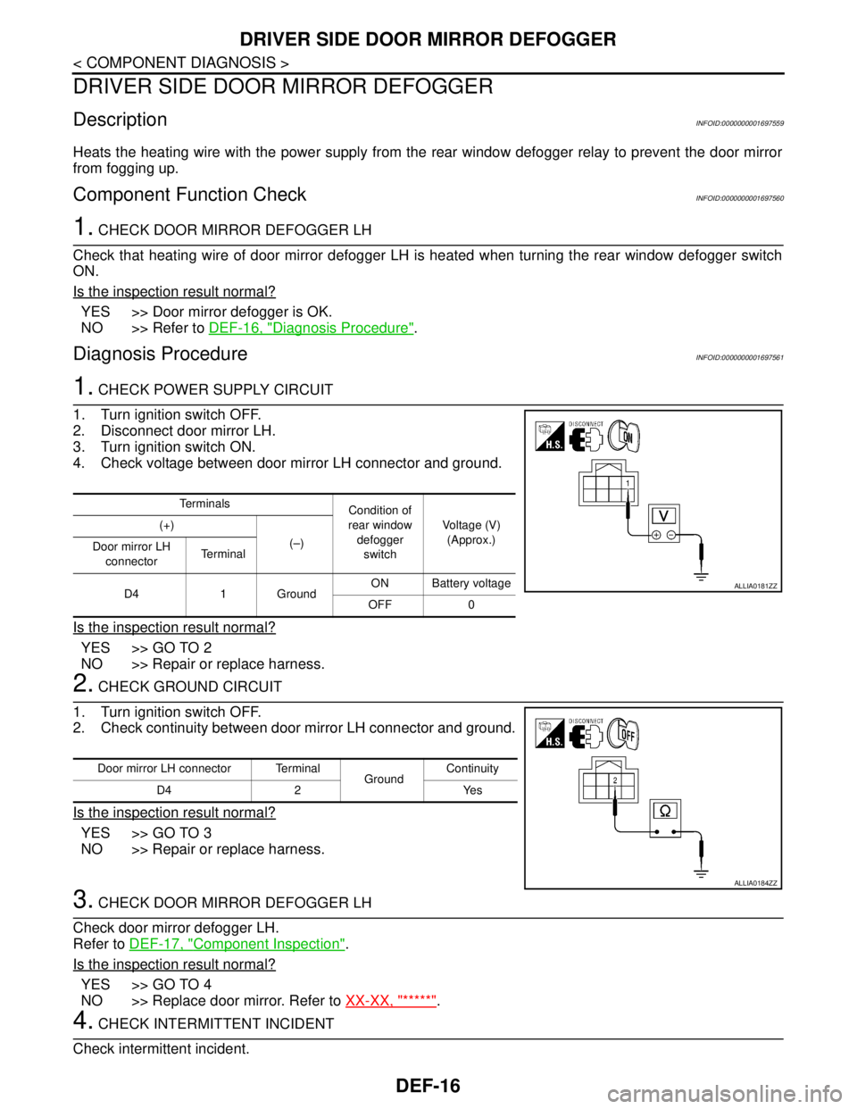
1. CHECK POWER SUPPLY CIRCUIT
1. Turn ignition switch OFF.
2. Disconnect door mirror LH.
3. Turn ignition switch ON.
4. Check voltage between door mirror LH connector and ground.
Is the inspection result normal?
YES >> GO TO 2
NO >> Repair or replace harness.
2. CHECK GROUND CIRCUIT
1. Turn ignition switch OFF.
2. Check continuity between door mirror LH connector and ground.
Is the inspection result normal?
YES >> GO TO 3
NO >> Repair or replace harness.
3. CHECK DOOR MIRROR DEFOGGER LH
Check door mirror defogger LH.
Refer to DEF-17, "
Component Inspection".
Is the inspection result normal?
YES >> GO TO 4
NO >> Replace door mirror. Refer to XX-XX, "*****"
.
4. CHECK INTERMITTENT INCIDENT
Check intermittent incident.
Te r m i n a l s
Condition of
rear window
defogger
switchVoltage (V)
(Approx.) (+)
(–)
Door mirror LH
connectorTe r m i n a l
D4 1 GroundON Battery voltage
OFF 0
ALLIA0181ZZ
Door mirror LH connector Terminal
GroundContinuity
D4 2 Yes
ALLIA0184ZZ
Page 568 of 5883
DRIVER SIDE DOOR MIRROR DEFOGGER
DEF-17
< COMPONENT DIAGNOSIS >
C
D
E
F
G
H
I
J
K
MA
B
DEF
N
O
P
Refer to XX-XX, "*****".
Is the inspection result normal?
YES >> Check the following.
Battery power supply circuit.
Fuse block (J/B).
NO >> Repair or replace the malfunctioning parts.
Component InspectionINFOID:0000000001697562
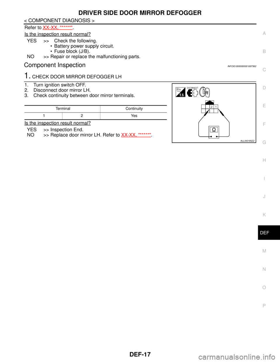
1. CHECK DOOR MIRROR DEFOGGER LH
1. Turn ignition switch OFF.
2. Disconnect door mirror LH.
3. Check continuity between door mirror terminals.
Is the inspection result normal?
YES >> Inspection End.
NO >> Replace door mirror LH. Refer to XX-XX, "*****"
.
Terminal Continuity
12 Yes
ALLIA0185ZZ
Page 569 of 5883
DEF-18
< COMPONENT DIAGNOSIS >
PASSENGER SIDE DOOR MIRROR DEFOGGER
PASSENGER SIDE DOOR MIRROR DEFOGGER
DescriptionINFOID:0000000001697563
Heats the heating wire with the power supply from the rear window defogger relay to prevent the door mirror
from fogging up.
Component Function CheckINFOID:0000000001697564
1.CHECK DOOR MIRROR DEFOGGER RH
Check that the heating wire of door mirror defogger RH is heated when turning the rear window defogger
switch ON.
Is the inspection result normal?
YES >> Door mirror defogger RH is OK.
NO >> Refer to DEF-18, "
Diagnosis Procedure".
Diagnosis ProcedureINFOID:0000000001697565
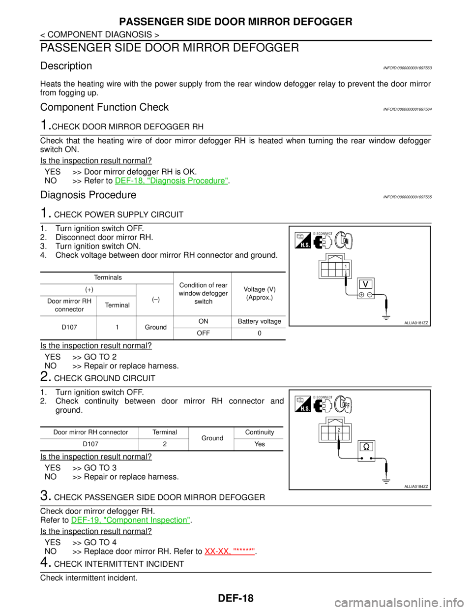
1. CHECK POWER SUPPLY CIRCUIT
1. Turn ignition switch OFF.
2. Disconnect door mirror RH.
3. Turn ignition switch ON.
4. Check voltage between door mirror RH connector and ground.
Is the inspection result normal?
YES >> GO TO 2
NO >> Repair or replace harness.
2. CHECK GROUND CIRCUIT
1. Turn ignition switch OFF.
2. Check continuity between door mirror RH connector and
ground.
Is the inspection result normal?
YES >> GO TO 3
NO >> Repair or replace harness.
3. CHECK PASSENGER SIDE DOOR MIRROR DEFOGGER
Check door mirror defogger RH.
Refer to DEF-19, "
Component Inspection".
Is the inspection result normal?
YES >> GO TO 4
NO >> Replace door mirror RH. Refer to XX-XX, "*****"
.
4. CHECK INTERMITTENT INCIDENT
Check intermittent incident.
Te r m i n a l s
Condition of rear
window defogger
switchVoltage (V)
(Approx.) (+)
(–)
Door mirror RH
connectorTe r m i n a l
D107 1 GroundON Battery voltage
OFF 0
ALLIA0181ZZ
Door mirror RH connector Terminal
GroundContinuity
D107 2 Yes
ALLIA0184ZZ
Page 570 of 5883
PASSENGER SIDE DOOR MIRROR DEFOGGER
DEF-19
< COMPONENT DIAGNOSIS >
C
D
E
F
G
H
I
J
K
MA
B
DEF
N
O
P
Refer to XX-XX, "*****".
Is the inspection result normal?
YES >> Check the following.
Battery power supply circuit.
Fuse block (J/B).
NO >> Repair or replace the malfunctioning parts.
Component InspectionINFOID:0000000001697566
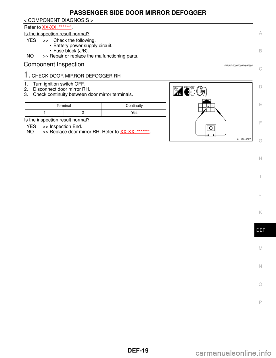
1. CHECK DOOR MIRROR DEFOGGER RH
1. Turn ignition switch OFF.
2. Disconnect door mirror RH.
3. Check continuity between door mirror terminals.
Is the inspection result normal?
YES >> Inspection End.
NO >> Replace door mirror RH. Refer to XX-XX, "*****"
.
Terminal Continuity
12 Yes
ALLIA0185ZZ