engine oil type NISSAN TIIDA 2007 Service Owner's Manual
[x] Cancel search | Manufacturer: NISSAN, Model Year: 2007, Model line: TIIDA, Model: NISSAN TIIDA 2007Pages: 5883, PDF Size: 78.95 MB
Page 2885 of 5883
![NISSAN TIIDA 2007 Service Owners Manual EM-238
< SERVICE DATA AND SPECIFICATIONS (SDS) [MR18DE]
SERVICE DATA AND SPECIFICATIONS (SDS)
SERVICE DATA AND SPECIFICATIONS (SDS)
SERVICE DATA AND SPECIFICATIONS (SDS)
Standard and LimitINFOID:00000 NISSAN TIIDA 2007 Service Owners Manual EM-238
< SERVICE DATA AND SPECIFICATIONS (SDS) [MR18DE]
SERVICE DATA AND SPECIFICATIONS (SDS)
SERVICE DATA AND SPECIFICATIONS (SDS)
SERVICE DATA AND SPECIFICATIONS (SDS)
Standard and LimitINFOID:00000](/img/5/57395/w960_57395-2884.png)
EM-238
< SERVICE DATA AND SPECIFICATIONS (SDS) [MR18DE]
SERVICE DATA AND SPECIFICATIONS (SDS)
SERVICE DATA AND SPECIFICATIONS (SDS)
SERVICE DATA AND SPECIFICATIONS (SDS)
Standard and LimitINFOID:0000000001337815
GENERAL SPECIFICATIONS
DRIVE BELT
WATER CONTROL VALVE
EXHAUST MANIFOLD
Unit: mm (in)
THERMOSTAT
SPARK PLUG
Unit: mm (in)
CYLINDER HEAD
Engine typeMR18DE
Cylinder arrangementIn-line 4
Displacement
cm
3 (cu in)1,798 (109.71)
Bore and stroke mm (in) 84.0 x 81.1 (3.307 x 3.192)
Valve arrangementDOHC
Firing order1-3-4-2
Number of piston ringsCompression 2
Oil 1
Compression ratio9.9
Compression pressure
kPa (bar, kg/cm
2 , psi) / 250 rpmStandard 1,500 (15.0, 15.3, 217.6)
Minimum 1,200 (12.0, 12.2, 174)
Differential limit between cylinders 100 (1.0, 1.0, 15)
Tension of drive belt Auto adjustment by auto-tensioner
Valve opening temperature 93.5 - 96.5°C (200 - 206°F)
Maximum valve lift 8 mm/ 108°C (0.315 in/ 226°F)
Valve closing temperature More than 90°C (194°F)
Items Limit
Surface distortionEach exhaust port 0.3 (0.012)
Entire part 0.7 (0.028)
Valve opening temperature 80.5 - 83.5°C (177 - 182°F)
Maximum valve lift 8 mm/ 95°C (0.315 in/ 203°F)
Valve closing temperature More than 77°C (171°F)
Plug typePlatinum-tipped TYPE
MakeNGK
Standard typePLZKAR6A-11
Spark plug gapNominal: 1.1 (0.043)
Page 2897 of 5883
![NISSAN TIIDA 2007 Service Owners Manual EM-250
< SYMPTOM DIAGNOSIS >[K9K]
NOISE, VIBRATION AND HARSHNESS (NVH) TROUBLESHOOTING
Use the Chart Below to Help You Find the Cause of the Symptom
INFOID:0000000001381449
1. Locate the area where no NISSAN TIIDA 2007 Service Owners Manual EM-250
< SYMPTOM DIAGNOSIS >[K9K]
NOISE, VIBRATION AND HARSHNESS (NVH) TROUBLESHOOTING
Use the Chart Below to Help You Find the Cause of the Symptom
INFOID:0000000001381449
1. Locate the area where no](/img/5/57395/w960_57395-2896.png)
EM-250
< SYMPTOM DIAGNOSIS >[K9K]
NOISE, VIBRATION AND HARSHNESS (NVH) TROUBLESHOOTING
Use the Chart Below to Help You Find the Cause of the Symptom
INFOID:0000000001381449
1. Locate the area where noise occurs.
2. Confirm the type of noise.
3. Specify the operating condition of engine.
4. Check specified noise source.
If necessary, repair or replace these parts.
A: Closely related B: Related C: Sometimes related —: Not relatedLocation
of noiseType of
noiseOperating condition of engine
Source of
noiseCheck itemRefer-
ence page Before
warm-
upAfter
warm-
upWhen
start-
ingWhen
idlingWhen
racingWhile
driving
Top of en-
gine
Rocker
cover
Cylinder
headTicking or
clickingCA—AB—Tappet
noiseValve clearanceEM-266
Crank-
shaft pul-
ley
Cylinder
block
(Side of
engine)
Oil panSlap or
rapA——B B APiston
slap noisePiston ring end gapEM-330
Front of
engine
Timing
belt coverTapping or
tickingAA—BBBTiming
belt ten-
sioner
noiseTiming belt tensioner
operationEM-291
Front of
engineSqueak-
ing or fizz-
ingAB—B—CDrive belts
(Sticking
or slip-
ping)Drive belts deflectionEM-263
Squall
CreakAB—BABWater
pump
noiseWater pump operationCO-66
Page 3011 of 5883
EXL-10
< FUNCTION DIAGNOSIS >
HEADLAMP (XENON)
HEADLAMP (XENON)
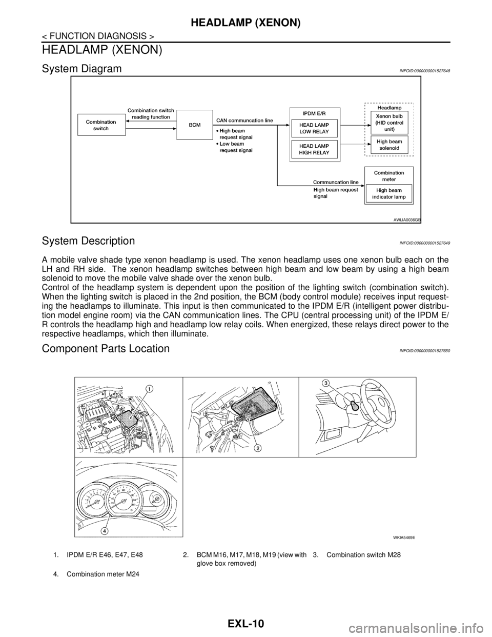
System DiagramINFOID:0000000001527648
System DescriptionINFOID:0000000001527649
A mobile valve shade type xenon headlamp is used. The xenon headlamp uses one xenon bulb each on the
LH and RH side. The xenon headlamp switches between high beam and low beam by using a high beam
solenoid to move the mobile valve shade over the xenon bulb.
Control of the headlamp system is dependent upon the position of the lighting switch (combination switch).
When the lighting switch is placed in the 2nd position, the BCM (body control module) receives input request-
ing the headlamps to illuminate. This input is then communicated to the IPDM E/R (intelligent power distribu-
tion model engine room) via the CAN communication lines. The CPU (central processing unit) of the IPDM E/
R controls the headlamp high and headlamp low relay coils. When energized, these relays direct power to the
respective headlamps, which then illuminate.
Component Parts LocationINFOID:0000000001527650
AWLIA0036GB
1. IPDM E/R E46, E47, E48 2. BCM M16, M17, M18, M19 (view with
glove box removed)3. Combination switch M28
4. Combination meter M24
WKIA5469E
Page 3084 of 5883
FRONT FOG LAMP
EXL-83
< ON-VEHICLE MAINTENANCE >
C
D
E
F
G
H
I
J
K
MA
B
EXL
N
O
P
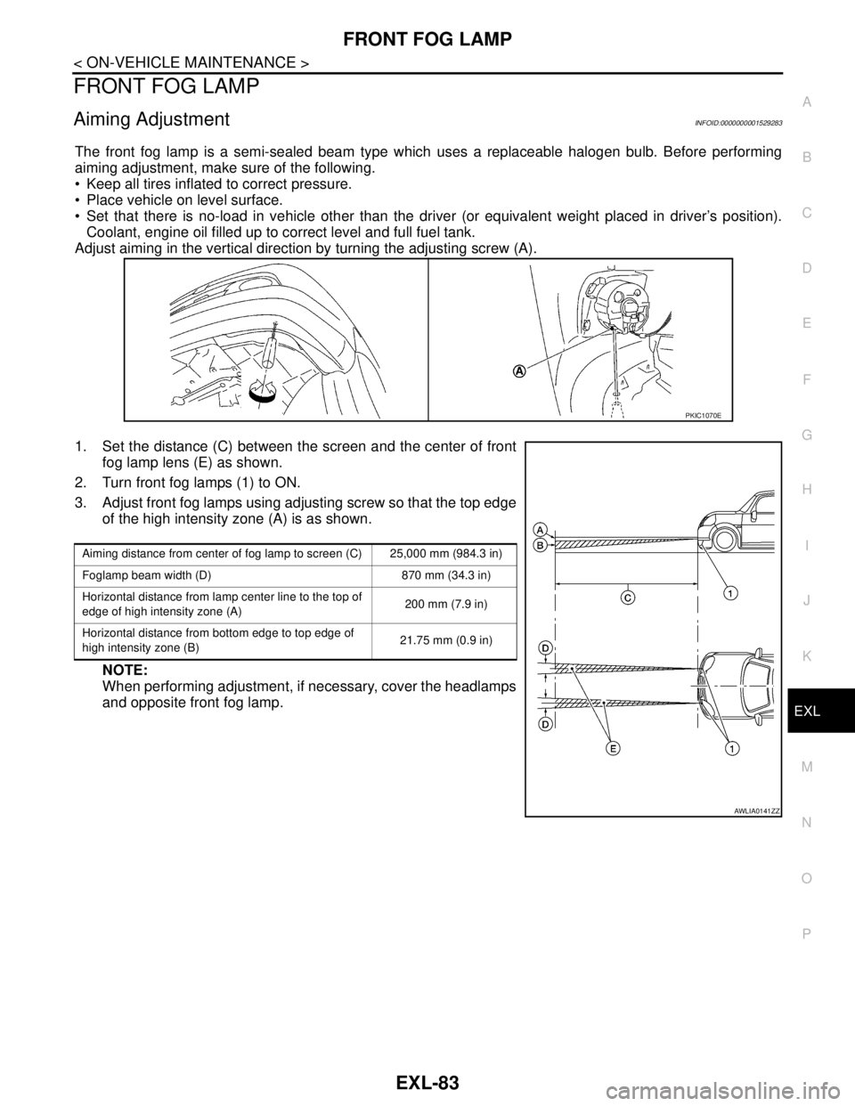
FRONT FOG LAMP
Aiming AdjustmentINFOID:0000000001529283
The front fog lamp is a semi-sealed beam type which uses a replaceable halogen bulb. Before performing
aiming adjustment, make sure of the following.
Keep all tires inflated to correct pressure.
Place vehicle on level surface.
Set that there is no-load in vehicle other than the driver (or equivalent weight placed in driver’s position).
Coolant, engine oil filled up to correct level and full fuel tank.
Adjust aiming in the vertical direction by turning the adjusting screw (A).
1. Set the distance (C) between the screen and the center of front
fog lamp lens (E) as shown.
2. Turn front fog lamps (1) to ON.
3. Adjust front fog lamps using adjusting screw so that the top edge
of the high intensity zone (A) is as shown.
NOTE:
When performing adjustment, if necessary, cover the headlamps
and opposite front fog lamp.
PKIC1070E
Aiming distance from center of fog lamp to screen (C) 25,000 mm (984.3 in)
Foglamp beam width (D) 870 mm (34.3 in)
Horizontal distance from lamp center line to the top of
edge of high intensity zone (A)200 mm (7.9 in)
Horizontal distance from bottom edge to top edge of
high intensity zone (B)21.75 mm (0.9 in)
AWLIA0141ZZ
Page 3178 of 5883
FSU-2
< PRECAUTION >
PRECAUTIONS
PRECAUTION
PRECAUTIONS
Precaution for Supplemental Restraint System (SRS) "AIR BAG" and "SEAT BELT
PRE-TENSIONER"
INFOID:0000000001716875
The Supplemental Restraint System such as “AIR BAG” and “SEAT BELT PRE-TENSIONER”, used along
with a front seat belt, helps to reduce the risk or severity of injury to the driver and front passenger for certain
types of collision. This system includes seat belt switch inputs and dual stage front air bag modules. The SRS
system uses the seat belt switches to determine the front air bag deployment, and may only deploy one front
air bag, depending on the severity of a collision and whether the front occupants are belted or unbelted.
Information necessary to service the system safely is included in the SR and SB section of this Service Man-
ual.
WARNING:
• To avoid rendering the SRS inoperative, which could increase the risk of personal injury or death in
the event of a collision which would result in air bag inflation, all maintenance must be performed by
an authorized NISSAN/INFINITI dealer.
Improper maintenance, including incorrect removal and installation of the SRS, can lead to personal
injury caused by unintentional activation of the system. For removal of Spiral Cable and Air Bag
Module, see the SR section.
Do not use electrical test equipment on any circuit related to the SRS unless instructed to in this
Service Manual. SRS wiring harnesses can be identified by yellow and/or orange harnesses or har-
ness connectors.
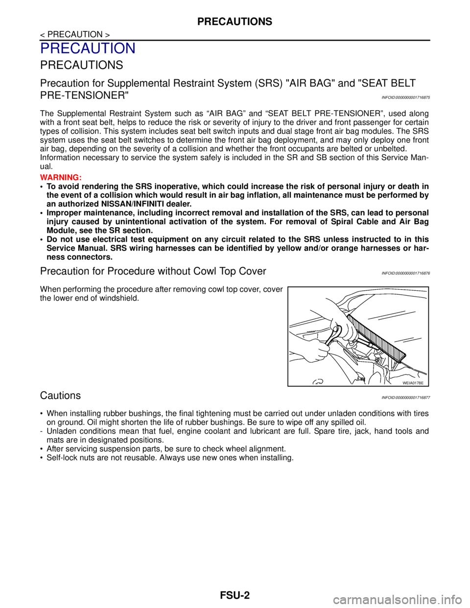
Precaution for Procedure without Cowl Top CoverINFOID:0000000001716876
When performing the procedure after removing cowl top cover, cover
the lower end of windshield.
CautionsINFOID:0000000001716877
When installing rubber bushings, the final tightening must be carried out under unladen conditions with tires
on ground. Oil might shorten the life of rubber bushings. Be sure to wipe off any spilled oil.
- Unladen conditions mean that fuel, engine coolant and lubricant are full. Spare tire, jack, hand tools and
mats are in designated positions.
After servicing suspension parts, be sure to check wheel alignment.
Self-lock nuts are not reusable. Always use new ones when installing.
WEIA0178E
Page 3332 of 5883
HA-50
< SERVICE DATA AND SPECIFICATIONS (SDS)
SERVICE DATA AND SPECIFICATIONS (SDS)
SERVICE DATA AND SPECIFICATIONS (SDS)
SERVICE DATA AND SPECIFICATIONS (SDS)
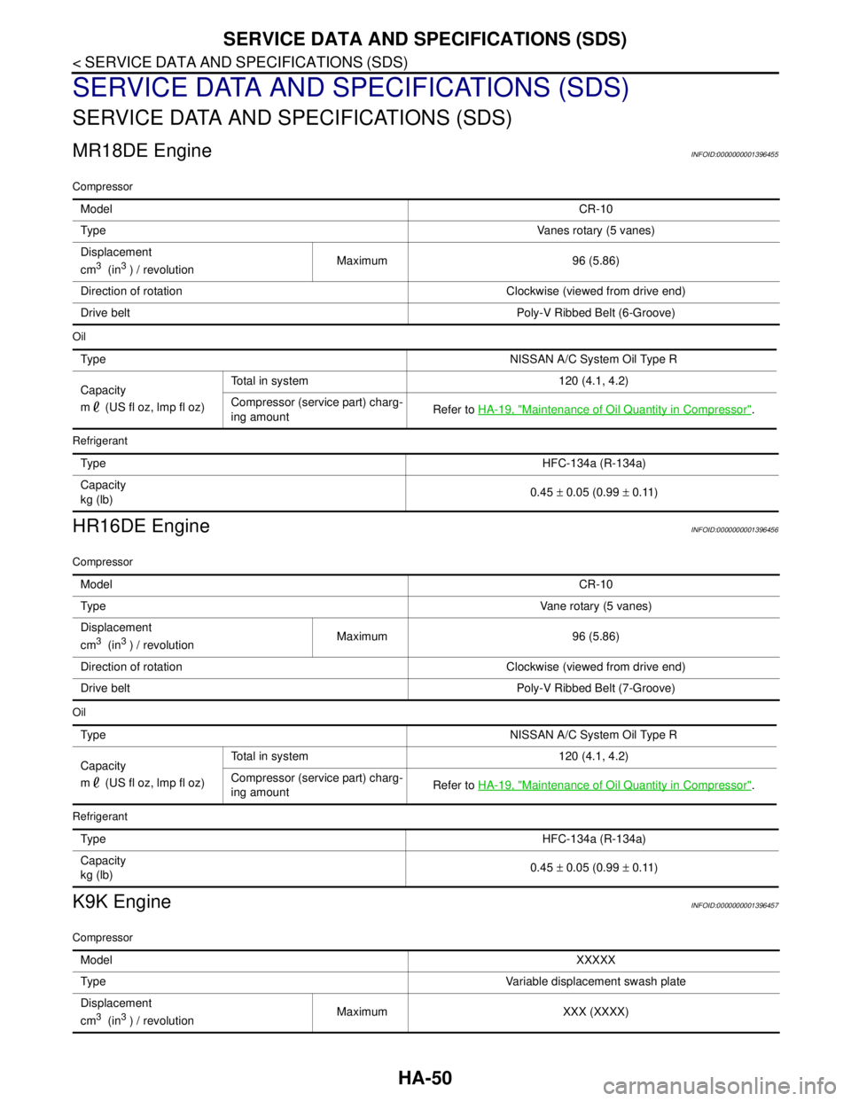
MR18DE EngineINFOID:0000000001396455
Compressor
Oil
Refrigerant
HR16DE EngineINFOID:0000000001396456
Compressor
Oil
Refrigerant
K9K EngineINFOID:0000000001396457
Compressor
ModelCR-10
Ty p eVanes rotary (5 vanes)
Displacement
cm
3 (in3 ) / revolutionMaximum 96 (5.86)
Direction of rotation Clockwise (viewed from drive end)
Drive beltPoly-V Ribbed Belt (6-Groove)
Ty p eNISSAN A/C System Oil Type R
Capacity
m (US fl oz, lmp fl oz)Total in system 120 (4.1, 4.2)
Compressor (service part) charg-
ing amountRefer to HA-19, "
Maintenance of Oil Quantity in Compressor".
Ty p eHFC-134a (R-134a)
Capacity
kg (lb)0.45 ± 0.05 (0.99 ± 0.11)
ModelCR-10
Ty p eVane rotary (5 vanes)
Displacement
cm
3 (in3 ) / revolutionMaximum 96 (5.86)
Direction of rotation Clockwise (viewed from drive end)
Drive beltPoly-V Ribbed Belt (7-Groove)
Ty p eNISSAN A/C System Oil Type R
Capacity
m (US fl oz, lmp fl oz)Total in system 120 (4.1, 4.2)
Compressor (service part) charg-
ing amountRefer to HA-19, "
Maintenance of Oil Quantity in Compressor".
Ty p eHFC-134a (R-134a)
Capacity
kg (lb)0.45 ± 0.05 (0.99 ± 0.11)
ModelXXXXX
Ty p eVariable displacement swash plate
Displacement
cm
3 (in3 ) / revolutionMaximum XXX (XXXX)
Page 4211 of 5883
![NISSAN TIIDA 2007 Service Owners Manual LU-4
< PRECAUTION >[HR16DE]
PRECAUTIONS
PRECAUTION
PRECAUTIONS
Precaution for Supplemental Restraint System (SRS) "AIR BAG" and "SEAT BELT
PRE-TENSIONER"
INFOID:0000000001516581
The Supplemental Rest NISSAN TIIDA 2007 Service Owners Manual LU-4
< PRECAUTION >[HR16DE]
PRECAUTIONS
PRECAUTION
PRECAUTIONS
Precaution for Supplemental Restraint System (SRS) "AIR BAG" and "SEAT BELT
PRE-TENSIONER"
INFOID:0000000001516581
The Supplemental Rest](/img/5/57395/w960_57395-4210.png)
LU-4
< PRECAUTION >[HR16DE]
PRECAUTIONS
PRECAUTION
PRECAUTIONS
Precaution for Supplemental Restraint System (SRS) "AIR BAG" and "SEAT BELT
PRE-TENSIONER"
INFOID:0000000001516581
The Supplemental Restraint System such as “AIR BAG” and “SEAT BELT PRE-TENSIONER”, used along
with a front seat belt, helps to reduce the risk or severity of injury to the driver and front passenger for certain
types of collision. Information necessary to service the system safely is included in the SR and SB section of
this Service Manual.
WARNING:
• To avoid rendering the SRS inoperative, which could increase the risk of personal injury or death in
the event of a collision which would result in air bag inflation, all maintenance must be performed by
an authorized NISSAN/INFINITI dealer.
Improper maintenance, including incorrect removal and installation of the SRS, can lead to personal
injury caused by unintentional activation of the system. For removal of Spiral Cable and Air Bag
Module, see the SR section.
Do not use electrical test equipment on any circuit related to the SRS unless instructed to in this
Service Manual. SRS wiring harnesses can be identified by yellow and/or orange harnesses or har-
ness connectors.
Liquid GasketINFOID:0000000001381524
LIQUID GASKET APPLICATION PROCEDURE
1. Remove old liquid gasket adhering to the liquid gasket application surface and the mating surface.
Remove liquid gasket completely from the liquid gasket application surface, mounting bolts, and bolt
holes.
2. Wipe the liquid gasket application surface and the mating surface with white gasoline (lighting and heating
use) to remove adhering moisture, grease and foreign materials.
3. Apply liquid gasket to the liquid gasket application surface.
Use Genuine liquid gasket or equivalent.
Within five minutes of liquid gasket application, install the mating component.
If liquid gasket protrudes, wipe it off immediately.
Do not retighten mounting bolts or nuts after the installation.
After 30 minutes or more have passed from the installation, fill engine oil and engine coolant.
Page 4219 of 5883
![NISSAN TIIDA 2007 Service Owners Manual LU-12
< PRECAUTION >[MR18DE]
PRECAUTIONS
PRECAUTION
PRECAUTIONS
Precaution for Supplemental Restraint System (SRS) "AIR BAG" and "SEAT BELT
PRE-TENSIONER"
INFOID:0000000001532084
The Supplemental Res NISSAN TIIDA 2007 Service Owners Manual LU-12
< PRECAUTION >[MR18DE]
PRECAUTIONS
PRECAUTION
PRECAUTIONS
Precaution for Supplemental Restraint System (SRS) "AIR BAG" and "SEAT BELT
PRE-TENSIONER"
INFOID:0000000001532084
The Supplemental Res](/img/5/57395/w960_57395-4218.png)
LU-12
< PRECAUTION >[MR18DE]
PRECAUTIONS
PRECAUTION
PRECAUTIONS
Precaution for Supplemental Restraint System (SRS) "AIR BAG" and "SEAT BELT
PRE-TENSIONER"
INFOID:0000000001532084
The Supplemental Restraint System such as “AIR BAG” and “SEAT BELT PRE-TENSIONER”, used along
with a front seat belt, helps to reduce the risk or severity of injury to the driver and front passenger for certain
types of collision. Information necessary to service the system safely is included in the SR and SB section of
this Service Manual.
WARNING:
To avoid rendering the SRS inoperative, which could increase the risk of personal injury or death in
the event of a collision which would result in air bag inflation, all maintenance must be performed by
an authorized NISSAN/INFINITI dealer.
Improper maintenance, including incorrect removal and installation of the SRS, can lead to personal
injury caused by unintentional activation of the system. For removal of Spiral Cable and Air Bag
Module, see the SR section.
Do not use electrical test equipment on any circuit related to the SRS unless instructed to in this
Service Manual. SRS wiring harnesses can be identified by yellow and/or orange harnesses or har-
ness connectors.
Precaution for Liquid GasketINFOID:0000000001337823
LIQUID GASKET APPLICATION PROCEDURE
1. Remove old liquid gasket adhering to the liquid gasket application surface and the mating surface.
Remove liquid gasket completely from the liquid gasket application surface, bolts, and bolt holes.
2. Wipe the liquid gasket application surface and the mating surface with white gasoline (lighting and heating
use) to remove adhering moisture, grease and foreign materials.
3. Attach liquid gasket tube to the Tool.
Use Genuine Silicone RTV Sealant or equivalent. Refer to
GI-27, "
Recommended Chemical Products and Sealants".
Within 5 minutes of liquid gasket application, install the mating
component.
If liquid gasket protrudes, wipe it off immediately.
Do not retighten bolts or nuts after the installation.
Wait 30 minutes or more after installation before refilling
engine oil and engine coolant.Tool number :WS39930000 ( — )
PBIC2160E
Page 4247 of 5883
PERIODIC MAINTENANCE
MA-7
< ON-VEHICLE MAINTENANCE >
C
D
E
F
G
H
I
J
K
L
MB
MAN
OA
PERIODIC MAINTENANCE
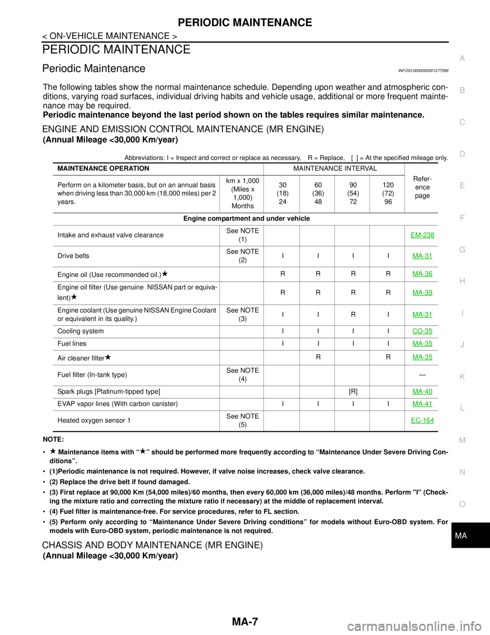
Periodic MaintenanceINFOID:0000000001277598
The following tables show the normal maintenance schedule. Depending upon weather and atmospheric con-
ditions, varying road surfaces, individual driving habits and vehicle usage, additional or more frequent mainte-
nance may be required.
Periodic maintenance beyond the last period shown on the tables requires similar maintenance.
ENGINE AND EMISSION CONTROL MAINTENANCE (MR ENGINE)
(Annual Mileage <30,000 Km/year)
Abbreviations: I = Inspect and correct or replace as necessary, R = Replace, [ ] = At the specified mileage only.
NOTE:
Maintenance items with “ ” should be performed more frequently according to “Maintenance Under Severe Driving Con-
ditions”.
(1)Periodic maintenance is not required. However, if valve noise increases, check valve clearance.
(2) Replace the drive belt if found damaged.
(3) First replace at 90,000 Km (54,000 miles)/60 months, then every 60,000 km (36,000 miles)/48 months. Perform "I" (Check-
ing the mixture ratio and correcting the mixture ratio if necessary) at the middle of replacement interval.
(4) Fuel filter is maintenance-free. For service procedures, refer to FL section.
(5) Perform only according to “Maintenance Under Severe Driving conditions” for models without Euro-OBD system. For
models with Euro-OBD system, periodic maintenance is not required.
CHASSIS AND BODY MAINTENANCE (MR ENGINE)
(Annual Mileage <30,000 Km/year)
MAINTENANCE OPERATIONMAINTENANCE INTERVAL
Refer-
ence
page Perform on a kilometer basis, but on an annual basis
when driving less than 30,000 km (18,000 miles) per 2
years.km x 1,000
(Miles x
1,000)
Months30
(18)
2460
(36)
4890
(54)
72120
(72)
96
Engine compartment and under vehicle
Intake and exhaust valve clearanceSee NOTE
(1)EM-238
Drive beltsSee NOTE
(2)IIIIMA-31
Engine oil (Use recommended oil.)RRRRMA-36
Engine oil filter (Use genuine NISSAN part or equiva-
lent)RRRRMA-39
Engine coolant (Use genuine NISSAN Engine Coolant
or equivalent in its quality.)See NOTE
(3)IIRIMA-31
Cooling system I I I ICO-35
Fuel lines I I I IMA-35
Air cleaner filterRRMA-35
Fuel filter (In-tank type)See NOTE
(4)—
Spark plugs [Platinum-tipped type] [R]MA-40
EVAP vapor lines (With carbon canister) I I I IMA-41
Heated oxygen sensor 1See NOTE
(5)EC-164
Page 4249 of 5883
PERIODIC MAINTENANCE
MA-9
< ON-VEHICLE MAINTENANCE >
C
D
E
F
G
H
I
J
K
L
MB
MAN
OA
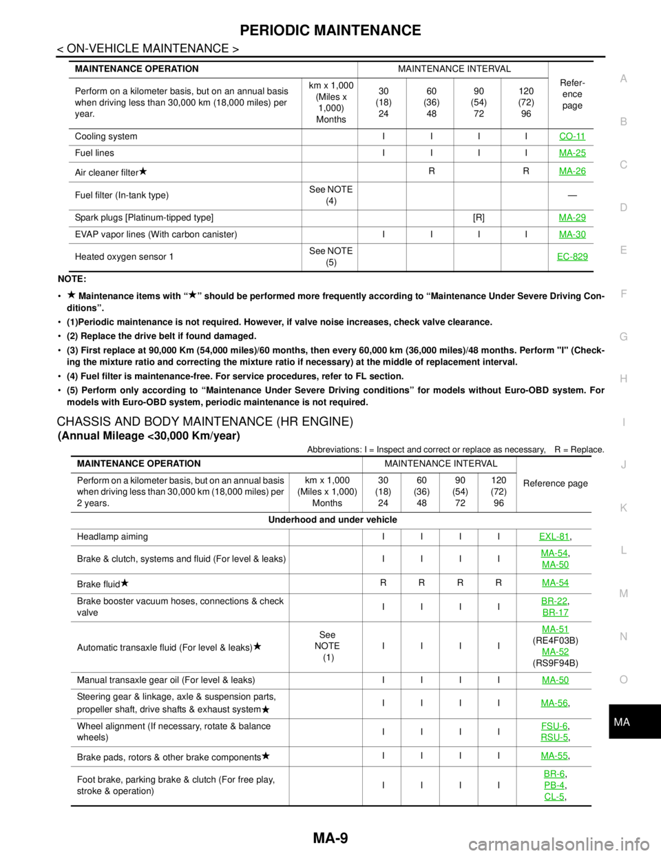
NOTE:
Maintenance items with “ ” should be performed more frequently according to “Maintenance Under Severe Driving Con-
ditions”.
(1)Periodic maintenance is not required. However, if valve noise increases, check valve clearance.
(2) Replace the drive belt if found damaged.
(3) First replace at 90,000 Km (54,000 miles)/60 months, then every 60,000 km (36,000 miles)/48 months. Perform "I" (Check-
ing the mixture ratio and correcting the mixture ratio if necessary) at the middle of replacement interval.
(4) Fuel filter is maintenance-free. For service procedures, refer to FL section.
(5) Perform only according to “Maintenance Under Severe Driving conditions” for models without Euro-OBD system. For
models with Euro-OBD system, periodic maintenance is not required.
CHASSIS AND BODY MAINTENANCE (HR ENGINE)
(Annual Mileage <30,000 Km/year)
Abbreviations: I = Inspect and correct or replace as necessary, R = Replace.
Cooling system I I I ICO-11
Fuel lines I I I IMA-25
Air cleaner filterRRMA-26
Fuel filter (In-tank type)See NOTE
(4)—
Spark plugs [Platinum-tipped type] [R]MA-29
EVAP vapor lines (With carbon canister) I I I IMA-30
Heated oxygen sensor 1See NOTE
(5)EC-829
MAINTENANCE OPERATIONMAINTENANCE INTERVAL
Refer-
ence
page Perform on a kilometer basis, but on an annual basis
when driving less than 30,000 km (18,000 miles) per
year.km x 1,000
(Miles x
1,000)
Months30
(18)
2460
(36)
4890
(54)
72120
(72)
96
MAINTENANCE OPERATIONMAINTENANCE INTERVAL
Reference page Perform on a kilometer basis, but on an annual basis
when driving less than 30,000 km (18,000 miles) per
2 years.km x 1,000
(Miles x 1,000)
Months30
(18)
2460
(36)
4890
(54)
72120
(72)
96
Underhood and under vehicle
Headlamp aiming IIIIEXL-81
,
Brake & clutch, systems and fluid (For level & leaks) IIIIMA-54
,
MA-50
Brake fluidRRRRMA-54
Brake booster vacuum hoses, connections & check
valveIIIIBR-22,
BR-17
Automatic transaxle fluid (For level & leaks)See
NOTE
(1)IIIIMA-51(RE4F03B)
MA-52
(RS9F94B)
Manual transaxle gear oil (For level & leaks) IIIIMA-50
Steering gear & linkage, axle & suspension parts,
propeller shaft, drive shafts & exhaust systemIIIIMA-56,
Wheel alignment (If necessary, rotate & balance
wheels)IIIIFSU-6
,
RSU-5
,
Brake pads, rotors & other brake componentsIIIIMA-55
,
Foot brake, parking brake & clutch (For free play,
stroke & operation)IIIIBR-6
,
PB-4
,
CL-5
,