oil filter NISSAN TIIDA 2007 Service Owner's Manual
[x] Cancel search | Manufacturer: NISSAN, Model Year: 2007, Model line: TIIDA, Model: NISSAN TIIDA 2007Pages: 5883, PDF Size: 78.95 MB
Page 2706 of 5883
CAMSHAFT
EM-59
< ON-VEHICLE REPAIR >[HR16DE]
C
D
E
F
G
H
I
J
K
L
MA
EM
N
P O
CAMSHAFT
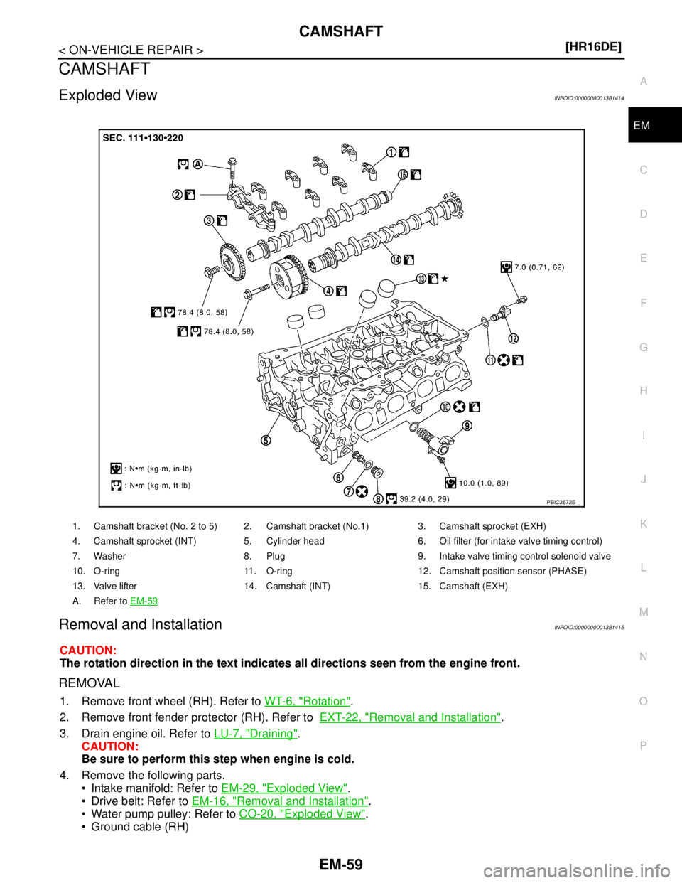
Exploded ViewINFOID:0000000001381414
Removal and InstallationINFOID:0000000001381415
CAUTION:
The rotation direction in the text indicates all directions seen from the engine front.
REMOVAL
1. Remove front wheel (RH). Refer to WT-6, "Rotation".
2. Remove front fender protector (RH). Refer to EXT-22, "
Removal and Installation".
3. Drain engine oil. Refer to LU-7, "
Draining".
CAUTION:
Be sure to perform this step when engine is cold.
4. Remove the following parts.
Intake manifold: Refer to EM-29, "
Exploded View".
Drive belt: Refer to EM-16, "
Removal and Installation".
Water pump pulley: Refer to CO-20, "
Exploded View".
Ground cable (RH)
1. Camshaft bracket (No. 2 to 5) 2. Camshaft bracket (No.1) 3. Camshaft sprocket (EXH)
4. Camshaft sprocket (INT) 5. Cylinder head 6. Oil filter (for intake valve timing control)
7. Washer 8. Plug 9. Intake valve timing control solenoid valve
10. O-ring 11. O-ring 12. Camshaft position sensor (PHASE)
13. Valve lifter 14. Camshaft (INT) 15. Camshaft (EXH)
A. Refer to EM-59
PBIC3672E
Page 2711 of 5883
EM-64
< ON-VEHICLE REPAIR >[HR16DE]
CAMSHAFT
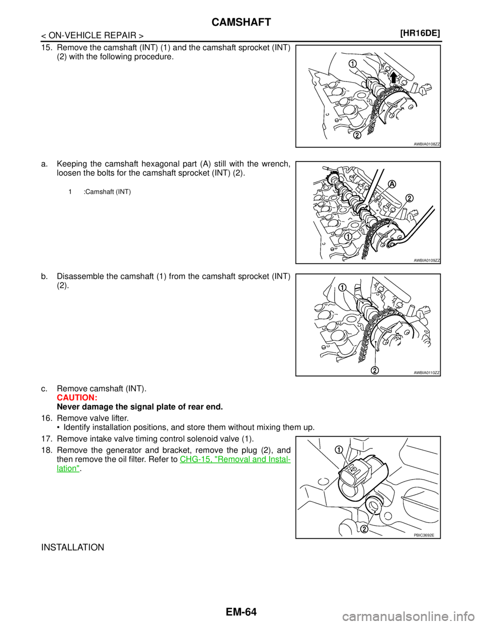
15. Remove the camshaft (INT) (1) and the camshaft sprocket (INT)
(2) with the following procedure.
a. Keeping the camshaft hexagonal part (A) still with the wrench,
loosen the bolts for the camshaft sprocket (INT) (2).
b. Disassemble the camshaft (1) from the camshaft sprocket (INT)
(2).
c. Remove camshaft (INT).
CAUTION:
Never damage the signal plate of rear end.
16. Remove valve lifter.
Identify installation positions, and store them without mixing them up.
17. Remove intake valve timing control solenoid valve (1).
18. Remove the generator and bracket, remove the plug (2), and
then remove the oil filter. Refer to CHG-15, "
Removal and Instal-
lation".
INSTALLATION
AWBIA0108ZZ
1 :Camshaft (INT)
AWBIA0109ZZ
AWBIA011 0ZZ
PBIC3692E
Page 2712 of 5883
CAMSHAFT
EM-65
< ON-VEHICLE REPAIR >[HR16DE]
C
D
E
F
G
H
I
J
K
L
MA
EM
N
P O
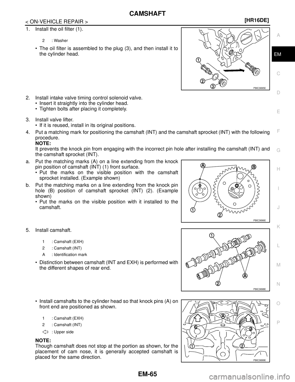
1. Install the oil filter (1).
The oil filter is assembled to the plug (3), and then install it to
the cylinder head.
2. Install intake valve timing control solenoid valve.
Insert it straightly into the cylinder head.
Tighten bolts after placing it completely.
3. Install valve lifter.
If it is reused, install in its original positions.
4. Put a matching mark for positioning the camshaft (INT) and the camshaft sprocket (INT) with the following
procedure.
NOTE:
It prevents the knock pin from engaging with the incorrect pin hole after installing the camshaft (INT) and
the camshaft sprocket (INT).
a. Put the matching marks (A) on a line extending from the knock
pin position of camshaft (INT) (1) front surface.
Put the marks on the visible position with the camshaft
sprocket installed. (Example shown)
b. Put the matching marks on a line extending from the knock pin
hole (B) position of camshaft sprocket (INT) (2). (Example
shown)
Put the marks on the visible position with it installed to the
camshaft.
5. Install camshaft.
Distinction between camshaft (INT and EXH) is performed with
the different shapes of rear end.
Install camshafts to the cylinder head so that knock pins (A) on
front end are positioned as shown.
NOTE:
Though camshaft does not stop at the portion as shown, for the
placement of cam nose, it is generally accepted camshaft is
placed for the same direction.
2: Washer
PBIC3695E
PBIC3696E
1 : Camshaft (EXH)
2 : Camshaft (INT)
A : Identification mark
PBIC3698E
1 : Camshaft (EXH)
2 : Camshaft (INT)
: Upper side
PBIC3699E
Page 2718 of 5883
CAMSHAFT
EM-71
< ON-VEHICLE REPAIR >[HR16DE]
C
D
E
F
G
H
I
J
K
L
MA
EM
N
P O
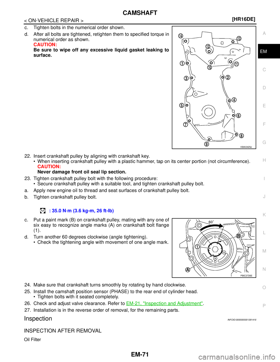
c. Tighten bolts in the numerical order shown.
d. After all bolts are tightened, retighten them to specified torque in
numerical order as shown.
CAUTION:
Be sure to wipe off any excessive liquid gasket leaking to
surface.
22. Insert crankshaft pulley by aligning with crankshaft key.
When inserting crankshaft pulley with a plastic hammer, tap on its center portion (not circumference).
CAUTION:
Never damage front oil seal lip section.
23. Tighten crankshaft pulley bolt with the following procedure:
Secure crankshaft pulley with a suitable tool, and tighten crankshaft pulley bolt.
a. Apply new engine oil to thread and seat surfaces of crankshaft pulley bolt.
b. Tighten crankshaft pulley bolt.
c. Put a paint mark (B) on crankshaft pulley, mating with any one of
six easy to recognize angle marks (A) on crankshaft bolt flange
(1).
d. Turn another 60 degrees clockwise (angle tightening).
Check the tightening angle with movement of one angle mark.
24. Make sure that crankshaft turns smoothly by rotating by hand clockwise.
25. Install the camshaft position sensor (PHASE) to the rear end of cylinder head.
Tighten bolts with it seated completely.
26. Check and adjust valve clearance. Refer to EM-21, "
Inspection and Adjustment".
27. Installation is in the reverse order of removal, for the remaining parts.
InspectionINFOID:0000000001381416
INSPECTION AFTER REMOVAL
Oil Filter
KBIA3429J
: 35.0 N·m (3.6 kg-m, 26 ft-lb)
PBIC3726E
Page 2719 of 5883
EM-72
< ON-VEHICLE REPAIR >[HR16DE]
CAMSHAFT
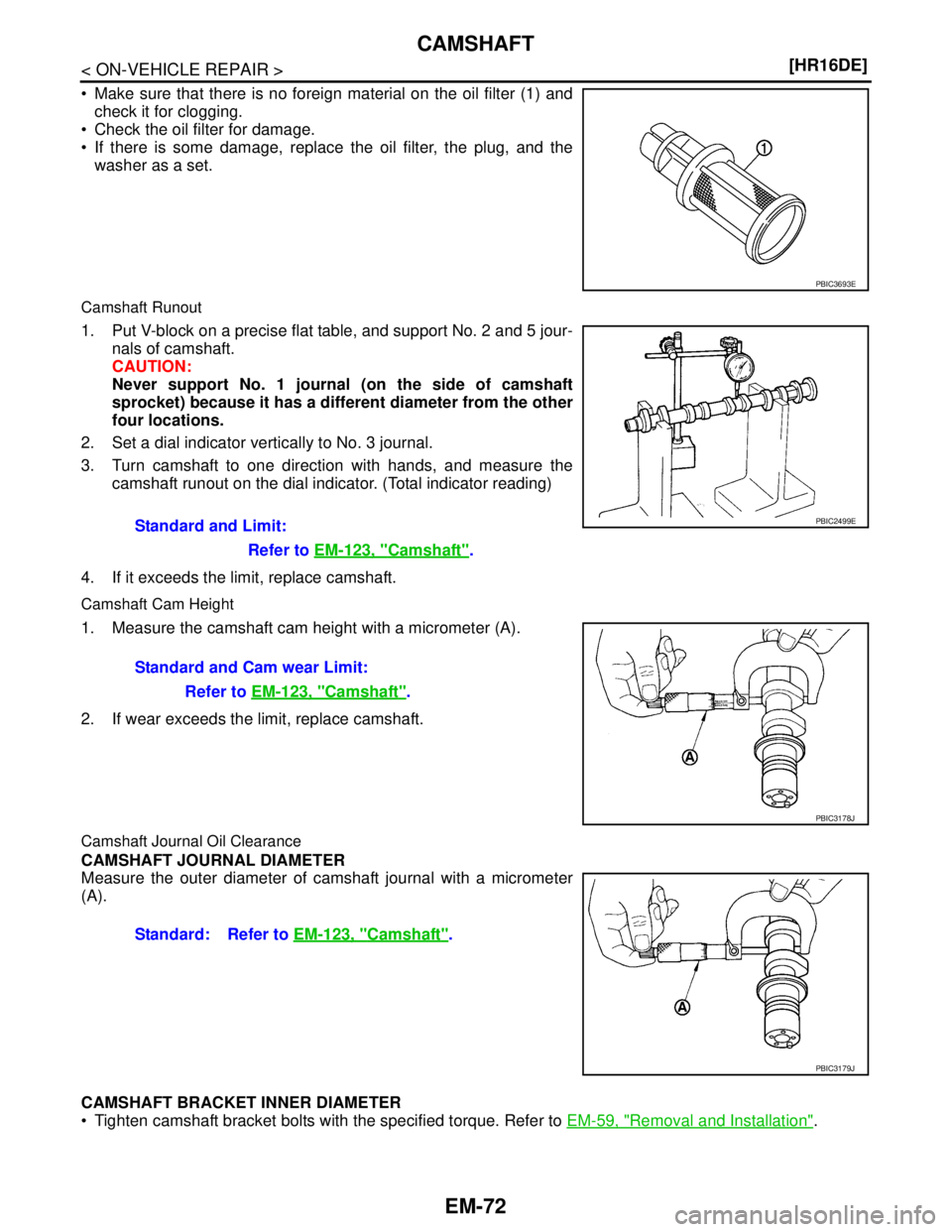
Make sure that there is no foreign material on the oil filter (1) and
check it for clogging.
Check the oil filter for damage.
If there is some damage, replace the oil filter, the plug, and the
washer as a set.
Camshaft Runout
1. Put V-block on a precise flat table, and support No. 2 and 5 jour-
nals of camshaft.
CAUTION:
Never support No. 1 journal (on the side of camshaft
sprocket) because it has a different diameter from the other
four locations.
2. Set a dial indicator vertically to No. 3 journal.
3. Turn camshaft to one direction with hands, and measure the
camshaft runout on the dial indicator. (Total indicator reading)
4. If it exceeds the limit, replace camshaft.
Camshaft Cam Height
1. Measure the camshaft cam height with a micrometer (A).
2. If wear exceeds the limit, replace camshaft.
Camshaft Journal Oil Clearance
CAMSHAFT JOURNAL DIAMETER
Measure the outer diameter of camshaft journal with a micrometer
(A).
CAMSHAFT BRACKET INNER DIAMETER
Tighten camshaft bracket bolts with the specified torque. Refer to EM-59, "
Removal and Installation".
PBIC3693E
Standard and Limit:
Refer to EM-123, "
Camshaft".
PBIC2499E
Standard and Cam wear Limit:
Refer to EM-123, "
Camshaft".
PBIC3178J
Standard: Refer to EM-123, "Camshaft".
PBIC3179J
Page 2723 of 5883
EM-76
< ON-VEHICLE REPAIR >[HR16DE]
CAMSHAFT
5. Perform the following inspection if engine oil does not come out from intake valve timing control solenoid
valve oil hole of the cylinder head.
Remove oil filter, and then clean it. Refer to EM-71, "
Inspection".
Clean oil groove between oil strainer and intake valve timing control solenoid valve. Refer to LU-3,
"Engine Lubrication System" and LU-3, "Engine Lubrication System Schematic".
6. Remove components between intake valve timing control solenoid valve and camshaft sprocket (INT),
and then check each oil groove for clogging.
Clean oil groove if necessary. Refer to LU-3, "
Engine Lubrication System" and LU-3, "Engine Lubrica-
tion System Schematic".
7. After inspection, installation is in the reverse order of removal.
Page 2743 of 5883
EM-96
< DISASSEMBLY AND ASSEMBLY >[HR16DE]
OIL PAN (UPPER)
OIL PAN (UPPER)
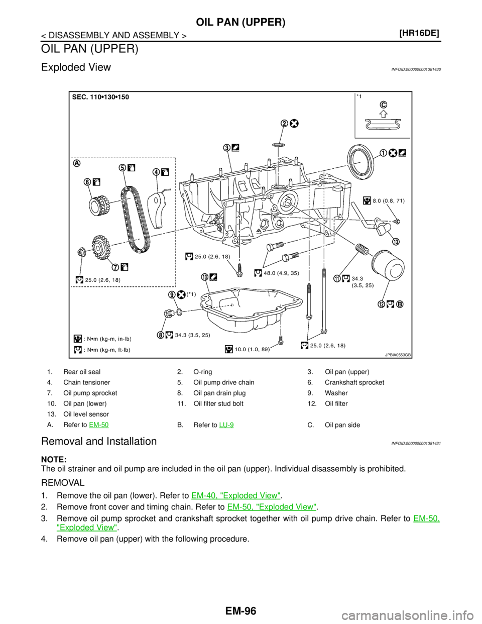
Exploded ViewINFOID:0000000001381430
Removal and InstallationINFOID:0000000001381431
NOTE:
The oil strainer and oil pump are included in the oil pan (upper). Individual disassembly is prohibited.
REMOVAL
1. Remove the oil pan (lower). Refer to EM-40, "Exploded View".
2. Remove front cover and timing chain. Refer to EM-50, "
Exploded View".
3. Remove oil pump sprocket and crankshaft sprocket together with oil pump drive chain. Refer to EM-50,
"Exploded View".
4. Remove oil pan (upper) with the following procedure.
1. Rear oil seal 2. O-ring 3. Oil pan (upper)
4. Chain tensioner 5. Oil pump drive chain 6. Crankshaft sprocket
7. Oil pump sprocket 8. Oil pan drain plug 9. Washer
10. Oil pan (lower) 11. Oil filter stud bolt 12. Oil filter
13. Oil level sensor
A. Refer to EM-50
B. Refer to LU-9C. Oil pan side
JPBIA0553GB
Page 2786 of 5883
PREPARATION
EM-139
< PREPARATION >[MR18DE]
C
D
E
F
G
H
I
J
K
L
MA
EM
N
P O
ST16610001
(J-23907)
Pilot bushing pullerRemoving crankshaft pilot bushing
KV11103000
(—)
Pulley pullerRemoving crankshaft pulley
KV991J0050
(J-44626)
Air fuel sensor SocketLoosening or tightening air fuel ratio A/F
sensor
a: 22 mm (0.87 in)
KV10114400
(J-38365)
Heated oxygen sensor wrenchLoosening or tightening rear heated oxy-
gen sensor
a: 22 mm (0.87 in)
KV11105210
(J-44716)
Stopper plateSecuring driveplate and flywheel
KV10115600
(J-38958)
Valve oil seal driftInstalling valve oil seal
Use side A.
a: 20 (0.79) dia.
b: 13 (0.51) dia.
c: 10.3 (0.406) dia.
d: 8 (0.31) dia.
e: 10.7 (0.421)
f: 5 (0.20)
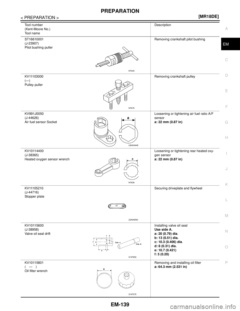
KV10115801
(—)
Oil filter wrenchRemoving and installing oil filter
a: 64.3 mm (2.531 in) Tool number
(Kent-Moore No.)
Tool nameDescription
NT045
NT676
LBIA0444E
NT636
ZZA0009D
S-NT603
S-NT375
Page 2813 of 5883
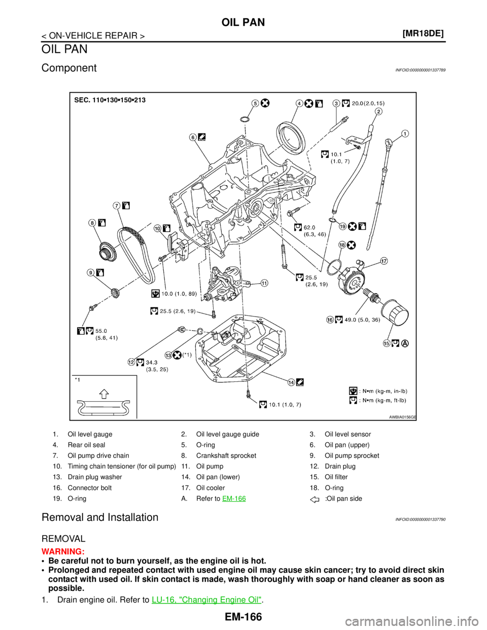
EM-166
< ON-VEHICLE REPAIR >[MR18DE]
OIL PAN
OIL PAN
ComponentINFOID:0000000001337789
Removal and InstallationINFOID:0000000001337790
REMOVAL
WARNING:
Be careful not to burn yourself, as the engine oil is hot.
Prolonged and repeated contact with used engine oil may cause skin cancer; try to avoid direct skin
contact with used oil. If skin contact is made, wash thoroughly with soap or hand cleaner as soon as
possible.
1. Drain engine oil. Refer to LU-16, "
Changing Engine Oil".
1. Oil level gauge 2. Oil level gauge guide 3. Oil level sensor
4. Rear oil seal 5. O-ring 6. Oil pan (upper)
7. Oil pump drive chain 8. Crankshaft sprocket 9. Oil pump sprocket
10. Timing chain tensioner (for oil pump) 11. Oil pump 12. Drain plug
13. Drain plug washer 14. Oil pan (lower) 15. Oil filter
16. Connector bolt 17. Oil cooler 18. O-ring
19. O-ring A. Refer to EM-166
:Oil pan side
AWBIA0156GB
Page 2814 of 5883
OIL PAN
EM-167
< ON-VEHICLE REPAIR >[MR18DE]
C
D
E
F
G
H
I
J
K
L
MA
EM
N
P O
2. Remove engine and transaxle assembly. Refer to EM-207.
3. Remove oil filter using Tool.
CAUTION:
When removing, prepare a shop cloth to absorb any engine oil leakage or spillage.
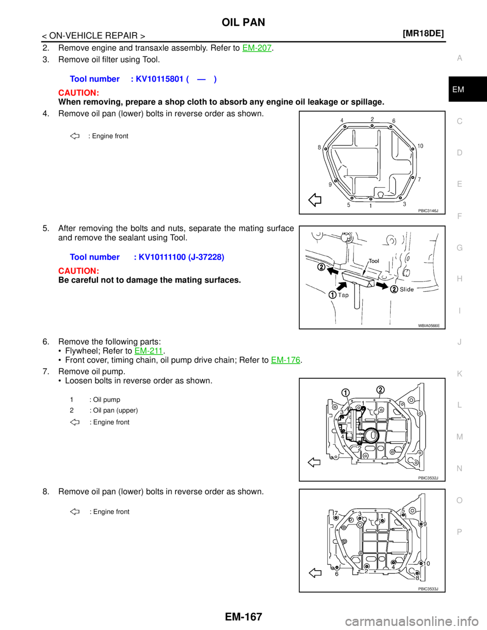
4. Remove oil pan (lower) bolts in reverse order as shown.
5. After removing the bolts and nuts, separate the mating surface
and remove the sealant using Tool.
CAUTION:
Be careful not to damage the mating surfaces.
6. Remove the following parts:
Flywheel; Refer to EM-211
.
Front cover, timing chain, oil pump drive chain; Refer to EM-176
.
7. Remove oil pump.
Loosen bolts in reverse order as shown.
8. Remove oil pan (lower) bolts in reverse order as shown.Tool number : KV10115801 ( — )
: Engine front
PBIC3146J
Tool number : KV10111100 (J-37228)
WBIA0566E
1: Oil pump
2 : Oil pan (upper)
: Engine front
PBIC3532J
: Engine front
PBIC3533J