tire pressure NISSAN TIIDA 2007 Service Owner's Guide
[x] Cancel search | Manufacturer: NISSAN, Model Year: 2007, Model line: TIIDA, Model: NISSAN TIIDA 2007Pages: 5883, PDF Size: 78.95 MB
Page 4577 of 5883

REAR SUSPENSION ASSEMBLY
RSU-5
< ON-VEHICLE MAINTENANCE >
C
D
F
G
H
I
J
K
L
MA
B
RSU
N
O
P
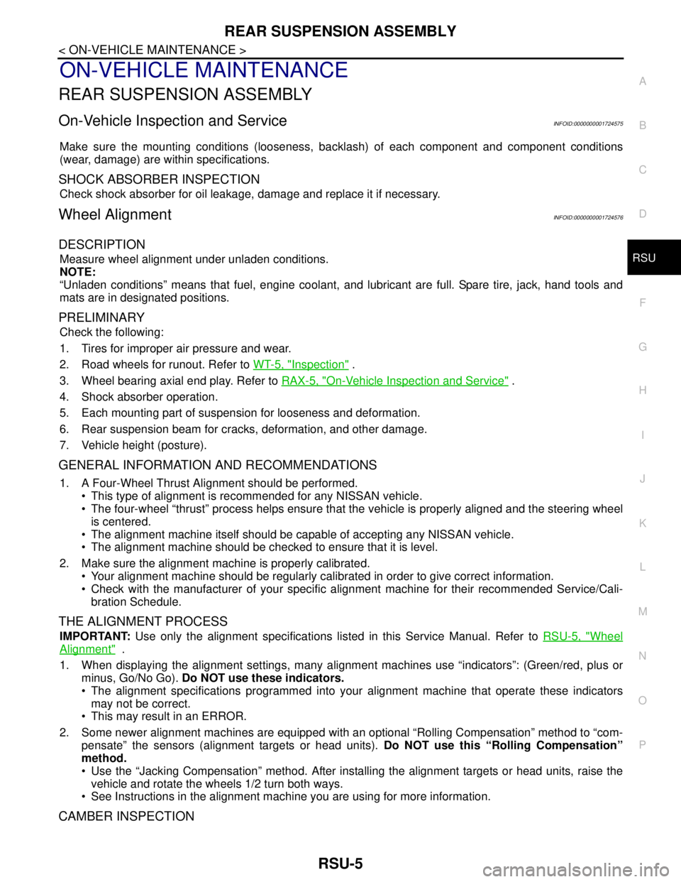
ON-VEHICLE MAINTENANCE
REAR SUSPENSION ASSEMBLY
On-Vehicle Inspection and ServiceINFOID:0000000001724575
Make sure the mounting conditions (looseness, backlash) of each component and component conditions
(wear, damage) are within specifications.
SHOCK ABSORBER INSPECTION
Check shock absorber for oil leakage, damage and replace it if necessary.
Wheel AlignmentINFOID:0000000001724576
DESCRIPTION
Measure wheel alignment under unladen conditions.
NOTE:
“Unladen conditions” means that fuel, engine coolant, and lubricant are full. Spare tire, jack, hand tools and
mats are in designated positions.
PRELIMINARY
Check the following:
1. Tires for improper air pressure and wear.
2. Road wheels for runout. Refer to WT-5, "
Inspection" .
3. Wheel bearing axial end play. Refer to RAX-5, "
On-Vehicle Inspection and Service" .
4. Shock absorber operation.
5. Each mounting part of suspension for looseness and deformation.
6. Rear suspension beam for cracks, deformation, and other damage.
7. Vehicle height (posture).
GENERAL INFORMATION AND RECOMMENDATIONS
1. A Four-Wheel Thrust Alignment should be performed.
This type of alignment is recommended for any NISSAN vehicle.
The four-wheel “thrust” process helps ensure that the vehicle is properly aligned and the steering wheel
is centered.
The alignment machine itself should be capable of accepting any NISSAN vehicle.
The alignment machine should be checked to ensure that it is level.
2. Make sure the alignment machine is properly calibrated.
Your alignment machine should be regularly calibrated in order to give correct information.
Check with the manufacturer of your specific alignment machine for their recommended Service/Cali-
bration Schedule.
THE ALIGNMENT PROCESS
IMPORTANT: Use only the alignment specifications listed in this Service Manual. Refer to RSU-5, "Wheel
Alignment" .
1. When displaying the alignment settings, many alignment machines use “indicators”: (Green/red, plus or
minus, Go/No Go). Do NOT use these indicators.
The alignment specifications programmed into your alignment machine that operate these indicators
may not be correct.
This may result in an ERROR.
2. Some newer alignment machines are equipped with an optional “Rolling Compensation” method to “com-
pensate” the sensors (alignment targets or head units). Do NOT use this “Rolling Compensation”
method.
Use the “Jacking Compensation” method. After installing the alignment targets or head units, raise the
vehicle and rotate the wheels 1/2 turn both ways.
See Instructions in the alignment machine you are using for more information.
CAMBER INSPECTION
Page 4767 of 5883

SR-24
< ON-VEHICLE REPAIR >
COLLISION DIAGNOSIS
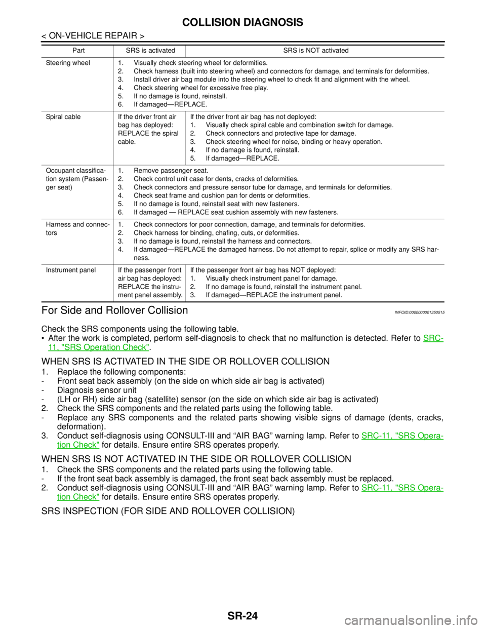
For Side and Rollover Collision
INFOID:0000000001350515
Check the SRS components using the following table.
After the work is completed, perform self-diagnosis to check that no malfunction is detected. Refer to SRC-
11 , "SRS Operation Check".
WHEN SRS IS ACTIVATED IN THE SIDE OR ROLLOVER COLLISION
1. Replace the following components:
- Front seat back assembly (on the side on which side air bag is activated)
- Diagnosis sensor unit
- (LH or RH) side air bag (satellite) sensor (on the side on which side air bag is activated)
2. Check the SRS components and the related parts using the following table.
- Replace any SRS components and the related parts showing visible signs of damage (dents, cracks,
deformation).
3. Conduct self-diagnosis using CONSULT-III and “AIR BAG” warning lamp. Refer to SRC-11, "
SRS Opera-
tion Check" for details. Ensure entire SRS operates properly.
WHEN SRS IS NOT ACTIVATED IN THE SIDE OR ROLLOVER COLLISION
1. Check the SRS components and the related parts using the following table.
- If the front seat back assembly is damaged, the front seat back assembly must be replaced.
2. Conduct self-diagnosis using CONSULT-III and “AIR BAG” warning lamp. Refer to SRC-11, "
SRS Opera-
tion Check" for details. Ensure entire SRS operates properly.
SRS INSPECTION (FOR SIDE AND ROLLOVER COLLISION)
Steering wheel 1. Visually check steering wheel for deformities.
2. Check harness (built into steering wheel) and connectors for damage, and terminals for deformities.
3. Install driver air bag module into the steering wheel to check fit and alignment with the wheel.
4. Check steering wheel for excessive free play.
5. If no damage is found, reinstall.
6. If damaged—REPLACE.
Spiral cable If the driver front air
bag has deployed:
REPLACE the spiral
cable.If the driver front air bag has not deployed:
1. Visually check spiral cable and combination switch for damage.
2. Check connectors and protective tape for damage.
3. Check steering wheel for noise, binding or heavy operation.
4. If no damage is found, reinstall.
5. If damaged—REPLACE.
Occupant classifica-
tion system (Passen-
ger seat)1. Remove passenger seat.
2. Check control unit case for dents, cracks of deformities.
3. Check connectors and pressure sensor tube for damage, and terminals for deformities.
4. Check seat frame and cushion pan for dents or deformities.
5. If no damage is found, reinstall seat with new fasteners.
6. If damaged — REPLACE seat cushion assembly with new fasteners.
Harness and connec-
tors1. Check connectors for poor connection, damage, and terminals for deformities.
2. Check harness for binding, chafing, cuts, or deformities.
3. If no damage is found, reinstall the harness and connectors.
4. If damaged—REPLACE the damaged harness. Do not attempt to repair, splice or modify any SRS har-
ness.
Instrument panel If the passenger front
air bag has deployed:
REPLACE the instru-
ment panel assembly.If the passenger front air bag has NOT deployed:
1. Visually check instrument panel for damage.
2. If no damage is found, reinstall the instrument panel.
3. If damaged—REPLACE the instrument panel. Part SRS is activated SRS is NOT activated
Page 4910 of 5883
![NISSAN TIIDA 2007 Service Owners Guide STC-36
< PRECAUTION >[EPS]
PRECAUTIONS
PRECAUTION
PRECAUTIONS
Precaution for Supplemental Restraint System (SRS) "AIR BAG" and "SEAT BELT
PRE-TENSIONER"
INFOID:0000000001697712
The Supplemental Restr NISSAN TIIDA 2007 Service Owners Guide STC-36
< PRECAUTION >[EPS]
PRECAUTIONS
PRECAUTION
PRECAUTIONS
Precaution for Supplemental Restraint System (SRS) "AIR BAG" and "SEAT BELT
PRE-TENSIONER"
INFOID:0000000001697712
The Supplemental Restr](/img/5/57395/w960_57395-4909.png)
STC-36
< PRECAUTION >[EPS]
PRECAUTIONS
PRECAUTION
PRECAUTIONS
Precaution for Supplemental Restraint System (SRS) "AIR BAG" and "SEAT BELT
PRE-TENSIONER"
INFOID:0000000001697712
The Supplemental Restraint System such as “AIR BAG” and “SEAT BELT PRE-TENSIONER”, used along
with a front seat belt, helps to reduce the risk or severity of injury to the driver and front passenger for certain
types of collision. Information necessary to service the system safely is included in the SR and SB section of
this Service Manual.
WARNING:
To avoid rendering the SRS inoperative, which could increase the risk of personal injury or death in
the event of a collision which would result in air bag inflation, all maintenance must be performed by
an authorized NISSAN/INFINITI dealer.
Improper maintenance, including incorrect removal and installation of the SRS, can lead to personal
injury caused by unintentional activation of the system. For removal of Spiral Cable and Air Bag
Module, see the SR section.
Do not use electrical test equipment on any circuit related to the SRS unless instructed to in this
Service Manual. SRS wiring harnesses can be identified by yellow and/or orange harnesses or har-
ness connectors.
Precaution Necessary for Steering Wheel Rotation After Battery Disconnect
INFOID:0000000001716731
NOTE:
This Procedure is applied only to models with Intelligent Key system and NATS (NISSAN ANTI-THEFT SYS-
TEM).
Remove and install all control units after disconnecting both battery cables with the ignition knob in the
″LOCK″ position.
Always use CONSULT-III to perform self-diagnosis as a part of each function inspection after finishing work.
If DTC is detected, perform trouble diagnosis according to self-diagnostic results.
For models equipped with the Intelligent Key system and NATS, an electrically controlled steering lock mech-
anism is adopted on the key cylinder.
For this reason, if the battery is disconnected or if the battery is discharged, the steering wheel will lock and
steering wheel rotation will become impossible.
If steering wheel rotation is required when battery power is interrupted, follow the procedure below before
starting the repair operation.
OPERATION PROCEDURE
1. Connect both battery cables.
NOTE:
Supply power using jumper cables if battery is discharged.
2. Use the Intelligent Key or mechanical key to turn the ignition switch to the ″ACC″ position. At this time, the
steering lock will be released.
3. Disconnect both battery cables. The steering lock will remain released and the steering wheel can be
rotated.
4. Perform the necessary repair operation.
5. When the repair work is completed, return the ignition switch to the ″LOCK″ position before connecting
the battery cables. (At this time, the steering lock mechanism will engage.)
6. Perform a self-diagnosis check of all control units using CONSULT-III.
Service Notice or Precaution for EPS SystemINFOID:0000000001697713
CAUTION:
Check or confirm the following item when performing the trouble diagnosis.
Check any possible causes by interviewing the symptom and it’s condition from the customer if any
malfunction, such as EPS warning lamp turns ON, occurs.
Check if air pressure and size of tires are proper, the specified part is used for the steering wheel,
and control unit is genuine part.
Page 4970 of 5883
![NISSAN TIIDA 2007 Service Owners Guide TM-24
< FUNCTION DIAGNOSIS >[TYPE 1 (4AT: RE4F03B)]
A/T CONTROL SYSTEM
The line pressure is temporarily reduced corresponding to a change
in engine torque when shifting gears (that is, when the shift NISSAN TIIDA 2007 Service Owners Guide TM-24
< FUNCTION DIAGNOSIS >[TYPE 1 (4AT: RE4F03B)]
A/T CONTROL SYSTEM
The line pressure is temporarily reduced corresponding to a change
in engine torque when shifting gears (that is, when the shift](/img/5/57395/w960_57395-4969.png)
TM-24
< FUNCTION DIAGNOSIS >[TYPE 1 (4AT: RE4F03B)]
A/T CONTROL SYSTEM
The line pressure is temporarily reduced corresponding to a change
in engine torque when shifting gears (that is, when the shift solenoid
valve is switched for clutch operation) to reduce shifting shock.
AT LOW FLUID TEMPERATURE
A/T fluid viscosity and frictional characteristics of the clutch facing change with A/T fluid temperature. Clutch
engaging or band-contacting pressure is compensated for, according to A/T fluid temperature, to stabilize
shifting quality.
The line pressure is reduced below 60°C (140°F) to prevent shift-
ing shock due to high viscosity of A/T fluid when temperature is
low.
Line pressure is increased to a maximum irrespective of the throt-
tle opening when A/T fluid temperature drops to −10°C (14°F). This
pressure rise is adopted to prevent a delay in clutch and brake
operation due to extreme drop of A/T fluid viscosity at low temper-
ature.
Shift ControlINFOID:0000000001694426
The shift is regulated entirely by electronic control to accommodate vehicle speed and varying engine opera-
tions. This is accomplished by electrical signals transmitted by the revolution sensor and the ECM (accelerator
pedal position sensor). This results in improved acceleration performance and fuel economy.
CONTROL OF SHIFT SOLENOID VALVES A AND B
The TCM activates shift solenoid valves A and B according to sig-
nals from the accelerator pedal position sensor and revolution sen-
sor to select the optimum gear position on the basis of the shift
schedule memorized in the TCM.
The shift solenoid valve performs simple ON-OFF operation. When
set to “ON”, the drain circuit closes and pilot pressure is applied to
the shift valve.
RELATION BETWEEN SHIFT SOLENOID VALVES A AND B AND GEAR POSITIONS
SCIA4828E
SCIA4829E
SCIA4830E
SAT008J
Page 5286 of 5883
![NISSAN TIIDA 2007 Service Owners Guide TM-340
< FUNCTION DIAGNOSIS >[TYPE 2 (4AT: RE4F03B)]
A/T CONTROL SYSTEM
The line pressure is temporarily reduced corresponding to a change
in engine torque when shifting gears (that is, when the shift NISSAN TIIDA 2007 Service Owners Guide TM-340
< FUNCTION DIAGNOSIS >[TYPE 2 (4AT: RE4F03B)]
A/T CONTROL SYSTEM
The line pressure is temporarily reduced corresponding to a change
in engine torque when shifting gears (that is, when the shift](/img/5/57395/w960_57395-5285.png)
TM-340
< FUNCTION DIAGNOSIS >[TYPE 2 (4AT: RE4F03B)]
A/T CONTROL SYSTEM
The line pressure is temporarily reduced corresponding to a change
in engine torque when shifting gears (that is, when the shift solenoid
valve is switched for clutch operation) to reduce shifting shock.
AT LOW FLUID TEMPERATURE
A/T fluid viscosity and frictional characteristics of the clutch facing change with A/T fluid temperature. Clutch
engaging or band-contacting pressure is compensated for, according to A/T fluid temperature, to stabilize
shifting quality.
The line pressure is reduced below 60°C (140°F) to prevent shift-
ing shock due to high viscosity of A/T fluid when temperature is
low.
Line pressure is increased to a maximum irrespective of the throt-
tle opening when A/T fluid temperature drops to −10°C (14°F). This
pressure rise is adopted to prevent a delay in clutch and brake
operation due to extreme drop of A/T fluid viscosity at low temper-
ature.
Shift ControlINFOID:0000000001714315
The shift is regulated entirely by electronic control to accommodate vehicle speed and varying engine opera-
tions. This is accomplished by electrical signals transmitted by the revolution sensor and the ECM (accelerator
pedal position sensor). This results in improved acceleration performance and fuel economy.
CONTROL OF SHIFT SOLENOID VALVES A AND B
The TCM activates shift solenoid valves A and B according to sig-
nals from the accelerator pedal position sensor and revolution sen-
sor to select the optimum gear position on the basis of the shift
schedule memorized in the TCM.
The shift solenoid valve performs simple ON-OFF operation. When
set to “ON”, the drain circuit closes and pilot pressure is applied to
the shift valve.
RELATION BETWEEN SHIFT SOLENOID VALVES A AND B AND GEAR POSITIONS
SCIA4828E
SCIA4829E
SCIA4830E
SAT008J
Page 5799 of 5883

WT-4
< SYMPTOM DIAGNOSIS >
NOISE, VIBRATION AND HARSHNESS (NVH) TROUBLESHOOTING
SYMPTOM DIAGNOSIS
NOISE, VIBRATION AND HARSHNESS (NVH) TROUBLESHOOTING
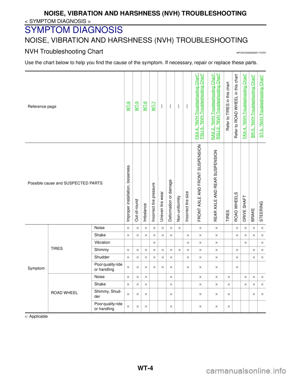
NVH Troubleshooting ChartINFOID:0000000001716761
Use the chart below to help you find the cause of the symptom. If necessary, repair or replace these parts.
×: ApplicableReference page
WT-6WT-5
WT-6
WT-7—
—
—
—
FA X - 4 , "
NVH Troubleshooting Chart
",
FSU-5, "
NVH Troubleshooting Chart
"
RAX-2, "
NVH Troubleshooting Chart
",
RSU-2, "
NVH Troubleshooting Chart
"
Refer to TIRES in this chart
Refer to ROAD WHEEL in this chart
FAX-4, "
NVH Troubleshooting Chart
"
BR-5, "
NVH Troubleshooting Chart
"
ST-5, "
NVH Troubleshooting Chart
"
Possible cause and SUSPECTED PARTS
Improper installation, looseness
Out-of-round
Imbalance
Incorrect tire pressure
Uneven tire wear
Deformation or damage
Non-uniformity
Incorrect tire size
FRONT AXLE AND FRONT SUSPENSION
REAR AXLE AND REAR SUSPENSION
TIRES
ROAD WHEELS
DRIVE SHAFT
BRAKE
STEERING
SymptomTIRESNoise× ×××××× × × ××××
Shake× ××××× × × × ××××
Vibration××××××
Shimmy× ××××××× × × × ××
Shudder× ××××× × × × × ××
Poor quality ride
or handling× ××××× × × × ×
ROAD WHEELNoise× ×× × × × × ×××
Shake× ×× × × × × ×××
Shimmy, Shud-
der×××× ×××××
Poor quality ride
or handling××× × × × ×
Page 5802 of 5883

SERVICE DATA AND SPECIFICATIONS (SDS)
WT-7
< SERVICE DATA AND SPECIFICATIONS (SDS)
C
D
F
G
H
I
J
K
L
MA
B
WT
N
O
P
SERVICE DATA AND SPECIFICATIONS (SDS)
SERVICE DATA AND SPECIFICATIONS (SDS)
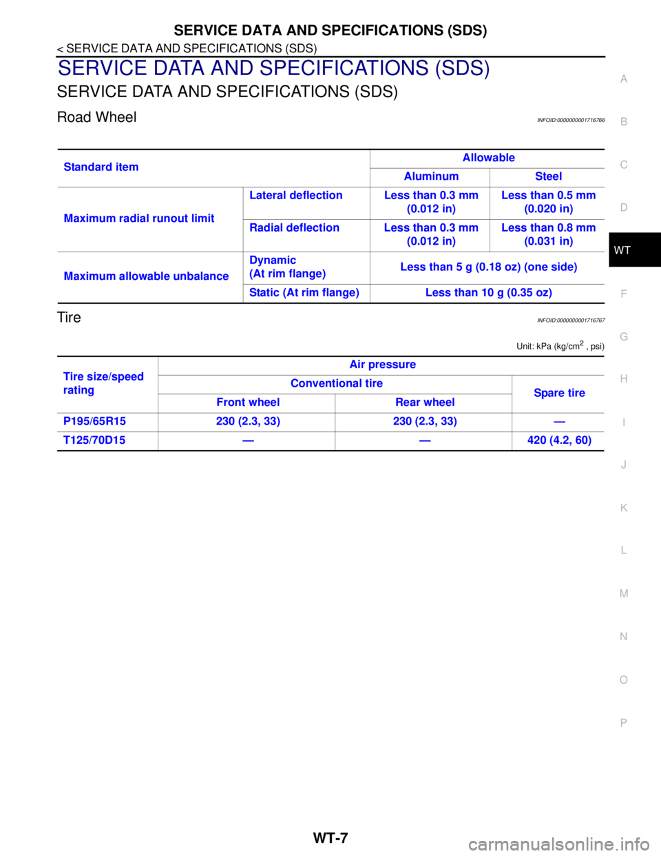
Road WheelINFOID:0000000001716766
TireINFOID:0000000001716767
Unit: kPa (kg/cm2 , psi)
Standard itemAllowable
Aluminum Steel
Maximum radial runout limitLateral deflection Less than 0.3 mm
(0.012 in)Less than 0.5 mm
(0.020 in)
Radial deflection Less than 0.3 mm
(0.012 in)Less than 0.8 mm
(0.031 in)
Maximum allowable unbalanceDynamic
(At rim flange)Less than 5 g (0.18 oz) (one side)
Static (At rim flange) Less than 10 g (0.35 oz)
Tire size/speed
ratingAir pressure
Conventional tire
Spare tire
Front wheel Rear wheel
P195/65R15 230 (2.3, 33) 230 (2.3, 33) —
T125/70D15 — — 420 (4.2, 60)