coolant NISSAN TIIDA 2007 Service Workshop Manual
[x] Cancel search | Manufacturer: NISSAN, Model Year: 2007, Model line: TIIDA, Model: NISSAN TIIDA 2007Pages: 5883, PDF Size: 78.95 MB
Page 1371 of 5883
EC-22
< BASIC INSPECTION >[HR16DE (WITH EURO-OBD)]
INSPECTION AND ADJUSTMENT
INSPECTION AND ADJUSTMENT
BASIC INSPECTION
BASIC INSPECTION : Special Repair RequirementINFOID:0000000001161123
1.INSPECTION START
1. Check service records for any recent repairs that may indicate a related malfunction, or a current need for
scheduled maintenance.
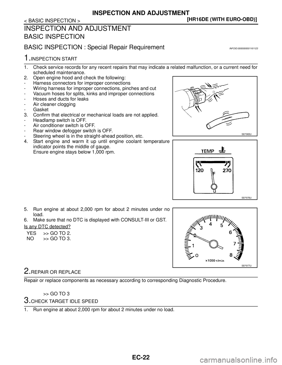
2. Open engine hood and check the following:
- Harness connectors for improper connections
- Wiring harness for improper connections, pinches and cut
- Vacuum hoses for splits, kinks and improper connections
- Hoses and ducts for leaks
- Air cleaner clogging
- Gasket
3. Confirm that electrical or mechanical loads are not applied.
- Headlamp switch is OFF.
- Air conditioner switch is OFF.
- Rear window defogger switch is OFF.
- Steering wheel is in the straight-ahead position, etc.
4. Start engine and warm it up until engine coolant temperature
indicator points the middle of gauge.
Ensure engine stays below 1,000 rpm.
5. Run engine at about 2,000 rpm for about 2 minutes under no
load.
6. Make sure that no DTC is displayed with CONSULT-III or GST.
Is any DTC detected?
YES >> GO TO 2.
NO >> GO TO 3.
2.REPAIR OR REPLACE
Repair or replace components as necessary according to corresponding Diagnostic Procedure.
>> GO TO 3
3.CHECK TARGET IDLE SPEED
1. Run engine at about 2,000 rpm for about 2 minutes under no load.
SEF983U
SEF976U
SEF977U
Page 1376 of 5883
INSPECTION AND ADJUSTMENT
EC-27
< BASIC INSPECTION >[HR16DE (WITH EURO-OBD)]
C
D
E
F
G
H
I
J
K
L
MA
EC
N
P O
quirementINFOID:0000000001161131
1.START
1. Make sure that accelerator pedal is fully released.
2. Turn ignition switch ON and wait at least 2 seconds.
3. Turn ignition switch OFF and wait at least 10 seconds.
4. Turn ignition switch ON and wait at least 2 seconds.
5. Turn ignition switch OFF and wait at least 10 seconds.
>> END
THROTTLE VALVE CLOSED POSITION LEARNING
THROTTLE VALVE CLOSED POSITION LEARNING : DescriptionINFOID:0000000001161132
Throttle Valve Closed Position Learning is a function of ECM to learn the fully closed position of the throttle
valve by monitoring the throttle position sensor output signal. It must be performed each time harness connec-
tor of electric throttle control actuator or ECM is disconnected.
THROTTLE VALVE CLOSED POSITION LEARNING : Special Repair Requirement
INFOID:0000000001161133
1.START
1. Make sure that accelerator pedal is fully released.
2. Turn ignition switch ON.
3. Turn ignition switch OFF and wait at least 10 seconds.
Make sure that throttle valve moves during above 10 seconds by confirming the operating sound.
>> END
IDLE AIR VOLUME LEARNING
IDLE AIR VOLUME LEARNING : DescriptionINFOID:0000000001161134
Idle Air Volume Learning is a function of ECM to learn the idle air volume that keeps each engine idle speed
within the specific range. It must be performed under any of the following conditions:
Each time electric throttle control actuator or ECM is replaced.
Idle speed or ignition timing is out of specification.
IDLE AIR VOLUME LEARNING : Special Repair RequirementINFOID:0000000001161135
1.PRECONDITIONING
Make sure that all of the following conditions are satisfied.
Learning will be cancelled if any of the following conditions are missed for even a moment.
Battery voltage: More than 12.9V (At idle)
Engine coolant temperature: 70 - 100°C (158 - 212°F)
Park/neutral position switch: ON
Electric load switch: OFF
(Air conditioner, headlamp, rear window defogger)
On vehicles equipped with daytime light systems, set lighting switch to the 1st position to light only
small lamps.
Steering wheel: Neutral (Straight-ahead position)
Vehicle speed: Stopped
Transmission: Warmed-up
- For A/T models with CONSULT-III
Drive vehicle until “ATF TEMP SE 1” in “DATA MONITOR” mode of “A/T” system indicates less than 0.9V.
- For A/T models without CONSULT-III and M/T models.
Drive vehicle for 10 minutes
Do you have CONSULT-III?
YES >> GO TO 2.
Page 1380 of 5883
ENGINE CONTROL SYSTEM
EC-31
< FUNCTION DIAGNOSIS >[HR16DE (WITH EURO-OBD)]
C
D
E
F
G
H
I
J
K
L
MA
EC
N
P O
System DescriptionINFOID:0000000001161139
ECM performs various controls such as fuel injection control and ignition timing control.
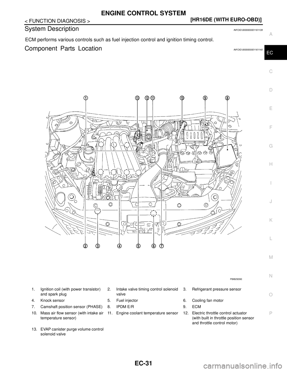
Component Parts LocationINFOID:0000000001161140
1. Ignition coil (with power transistor)
and spark plug2. Intake valve timing control solenoid
valve3. Refrigerant pressure sensor
4. Knock sensor 5. Fuel injector 6. Cooling fan motor
7. Camshaft position sensor (PHASE) 8. IPDM E/R 9. ECM
10. Mass air flow sensor (with intake air
temperature sensor)11. Engine coolant temperature sensor 12. Electric throttle control actuator
(with built in throttle position sensor
and throttle control motor)
13. EVAP canister purge volume control
solenoid valve
PBIB2939E
Page 1381 of 5883
EC-32
< FUNCTION DIAGNOSIS >[HR16DE (WITH EURO-OBD)]
ENGINE CONTROL SYSTEM
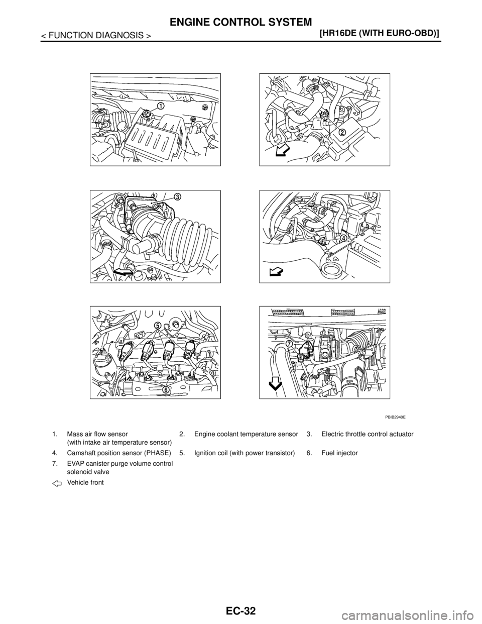
1. Mass air flow sensor
(with intake air temperature sensor)2. Engine coolant temperature sensor 3. Electric throttle control actuator
4. Camshaft position sensor (PHASE) 5. Ignition coil (with power transistor) 6. Fuel injector
7. EVAP canister purge volume control
solenoid valve
Vehicle front
PBIB2940E
Page 1385 of 5883
EC-36
< FUNCTION DIAGNOSIS >[HR16DE (WITH EURO-OBD)]
ENGINE CONTROL SYSTEM
Component Description
INFOID:0000000001161141
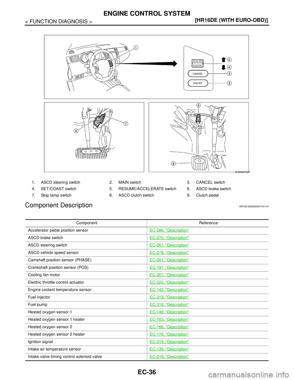
1. ASCD steering switch 2. MAIN switch 3. CANCEL switch
4. SET/COAST switch 5. RESUME/ACCELERATE switch 6. ASCD brake switch
7. Stop lamp switch 8. ASCD clutch switch 9. Clutch pedal
ALBIA0273ZZ
Component Reference
Accelerator pedal position sensorEC-286, "
Description"
ASCD brake switchEC-270, "Description"
ASCD steering switchEC-267, "Description"
ASCD vehicle speed sensorEC-278, "Description"
Camshaft position sensor (PHASE)EC-201, "Description"
Crankshaft position sensor (POS)EC-197, "Description"
Cooling fan motorEC-307, "Description"
Electric throttle control actuatorEC-222, "Description"
Engine coolant temperature sensorEC-142, "Description"
Fuel injectorEC-313, "Description"
Fuel pumpEC-316, "Description"
Heated oxygen sensor 1EC-148, "Description"
Heated oxygen sensor 1 heaterEC-163, "Description"
Heated oxygen sensor 2EC-166, "Description"
Heated oxygen sensor 2 heaterEC-176, "Description"
Ignition signalEC-319, "Description"
Intake air temperature sensorEC-139, "Description"
Intake valve timing control solenoid valveEC-219, "Description"
Page 1387 of 5883
EC-38
< FUNCTION DIAGNOSIS >[HR16DE (WITH EURO-OBD)]
MULTIPORT FUEL INJECTION SYSTEM
MULTIPORT FUEL INJECTION SYSTEM
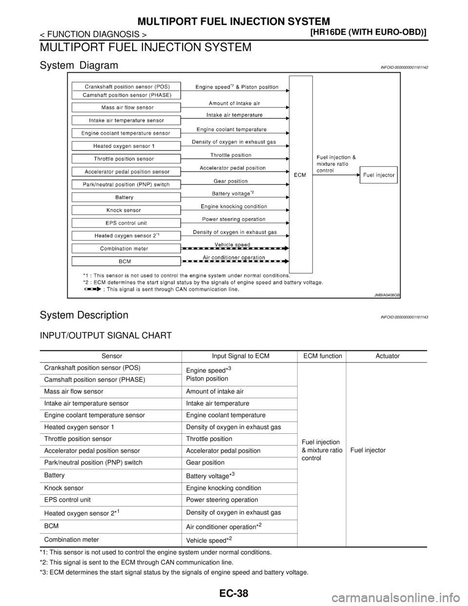
System DiagramINFOID:0000000001161142
System DescriptionINFOID:0000000001161143
INPUT/OUTPUT SIGNAL CHART
*1: This sensor is not used to control the engine system under normal conditions.
*2: This signal is sent to the ECM through CAN communication line.
*3: ECM determines the start signal status by the signals of engine speed and battery voltage.
JMBIA0408GB
Sensor Input Signal to ECM ECM function Actuator
Crankshaft position sensor (POS)
Engine speed*
3
Piston position
Fuel injection
& mixture ratio
controlFuel injector Camshaft position sensor (PHASE)
Mass air flow sensor Amount of intake air
Intake air temperature sensor Intake air temperature
Engine coolant temperature sensor Engine coolant temperature
Heated oxygen sensor 1 Density of oxygen in exhaust gas
Throttle position sensor Throttle position
Accelerator pedal position sensor Accelerator pedal position
Park/neutral position (PNP) switch Gear position
Battery
Battery voltage*
3
Knock sensor Engine knocking condition
EPS control unit Power steering operation
Heated oxygen sensor 2*
1Density of oxygen in exhaust gas
BCM
Air conditioner operation*
2
Combination meter
Vehicle speed*2
Page 1388 of 5883
MULTIPORT FUEL INJECTION SYSTEM
EC-39
< FUNCTION DIAGNOSIS >[HR16DE (WITH EURO-OBD)]
C
D
E
F
G
H
I
J
K
L
MA
EC
N
P O
SYSTEM DESCRIPTION
The amount of fuel injected from the fuel injector is determined by the ECM. The ECM controls the length of
time the valve remains open (injection pulse duration). The amount of fuel injected is a program value in the
ECM memory. The program value is preset by engine operating conditions. These conditions are determined
by input signals (for engine speed and intake air) from the crankshaft position sensor (POS), camshaft position
sensor (PHASE) and the mass air flow sensor.
VARIOUS FUEL INJECTION INCREASE/DECREASE COMPENSATION
In addition, the amount of fuel injected is compensated to improve engine performance under various operat-
ing conditions as listed below.
During warm-up
When starting the engine
During acceleration
Hot-engine operation
High-load, high-speed operation
During deceleration
During high engine speed operation
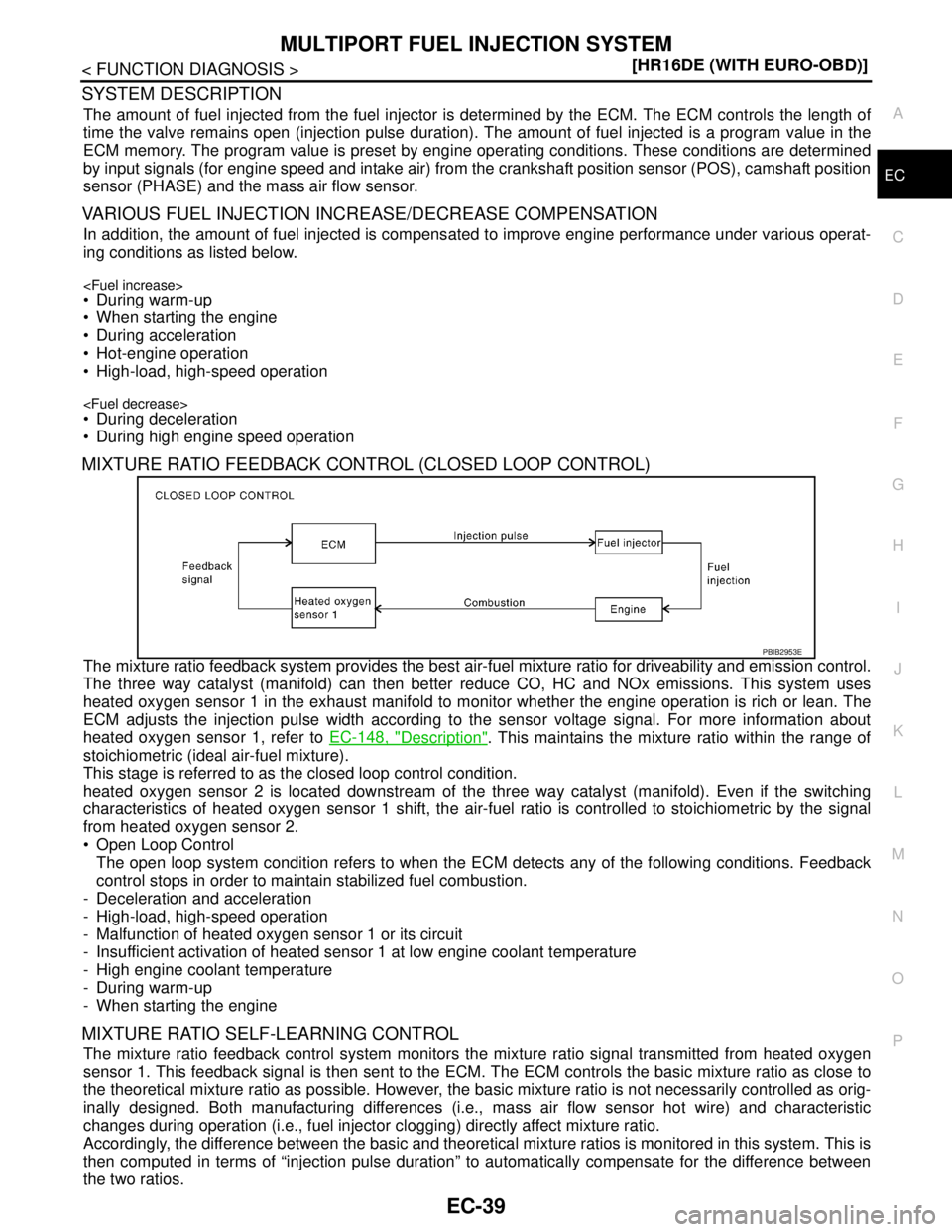
MIXTURE RATIO FEEDBACK CONTROL (CLOSED LOOP CONTROL)
The mixture ratio feedback system provides the best air-fuel mixture ratio for driveability and emission control.
The three way catalyst (manifold) can then better reduce CO, HC and NOx emissions. This system uses
heated oxygen sensor 1 in the exhaust manifold to monitor whether the engine operation is rich or lean. The
ECM adjusts the injection pulse width according to the sensor voltage signal. For more information about
heated oxygen sensor 1, refer to EC-148, "
Description". This maintains the mixture ratio within the range of
stoichiometric (ideal air-fuel mixture).
This stage is referred to as the closed loop control condition.
heated oxygen sensor 2 is located downstream of the three way catalyst (manifold). Even if the switching
characteristics of heated oxygen sensor 1 shift, the air-fuel ratio is controlled to stoichiometric by the signal
from heated oxygen sensor 2.
Open Loop Control
The open loop system condition refers to when the ECM detects any of the following conditions. Feedback
control stops in order to maintain stabilized fuel combustion.
- Deceleration and acceleration
- High-load, high-speed operation
- Malfunction of heated oxygen sensor 1 or its circuit
- Insufficient activation of heated sensor 1 at low engine coolant temperature
- High engine coolant temperature
- During warm-up
- When starting the engine
MIXTURE RATIO SELF-LEARNING CONTROL
The mixture ratio feedback control system monitors the mixture ratio signal transmitted from heated oxygen
sensor 1. This feedback signal is then sent to the ECM. The ECM controls the basic mixture ratio as close to
the theoretical mixture ratio as possible. However, the basic mixture ratio is not necessarily controlled as orig-
inally designed. Both manufacturing differences (i.e., mass air flow sensor hot wire) and characteristic
changes during operation (i.e., fuel injector clogging) directly affect mixture ratio.
Accordingly, the difference between the basic and theoretical mixture ratios is monitored in this system. This is
then computed in terms of “injection pulse duration” to automatically compensate for the difference between
the two ratios.
PBIB2953E
Page 1390 of 5883
MULTIPORT FUEL INJECTION SYSTEM
EC-41
< FUNCTION DIAGNOSIS >[HR16DE (WITH EURO-OBD)]
C
D
E
F
G
H
I
J
K
L
MA
EC
N
P O
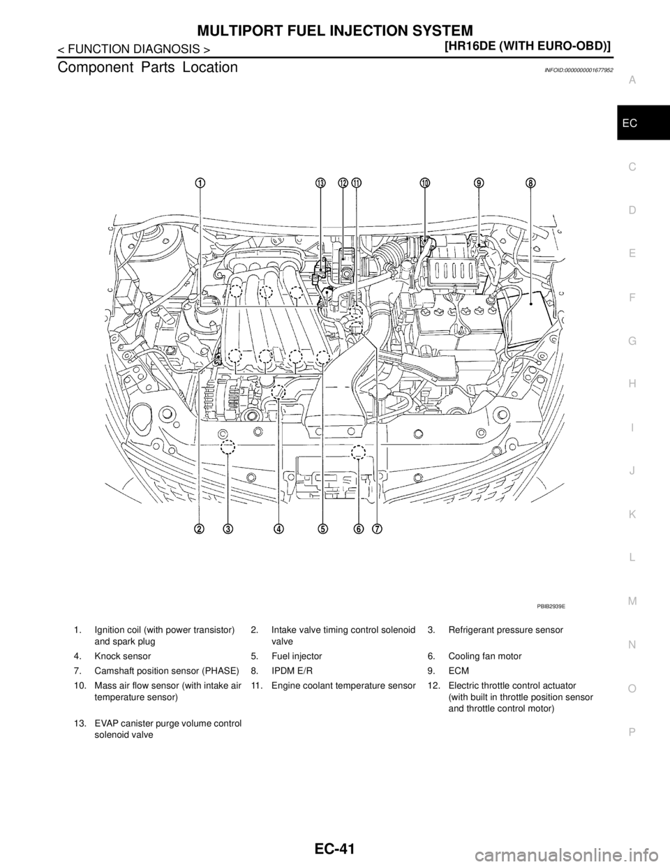
Component Parts LocationINFOID:0000000001677952
1. Ignition coil (with power transistor)
and spark plug2. Intake valve timing control solenoid
valve3. Refrigerant pressure sensor
4. Knock sensor 5. Fuel injector 6. Cooling fan motor
7. Camshaft position sensor (PHASE) 8. IPDM E/R 9. ECM
10. Mass air flow sensor (with intake air
temperature sensor)11. Engine coolant temperature sensor 12. Electric throttle control actuator
(with built in throttle position sensor
and throttle control motor)
13. EVAP canister purge volume control
solenoid valve
PBIB2939E
Page 1391 of 5883
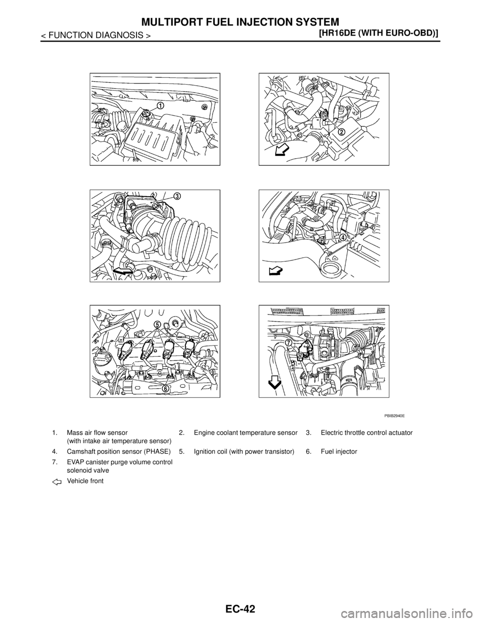
EC-42
< FUNCTION DIAGNOSIS >[HR16DE (WITH EURO-OBD)]
MULTIPORT FUEL INJECTION SYSTEM
1. Mass air flow sensor
(with intake air temperature sensor)2. Engine coolant temperature sensor 3. Electric throttle control actuator
4. Camshaft position sensor (PHASE) 5. Ignition coil (with power transistor) 6. Fuel injector
7. EVAP canister purge volume control
solenoid valve
Vehicle front
PBIB2940E
Page 1395 of 5883
EC-46
< FUNCTION DIAGNOSIS >[HR16DE (WITH EURO-OBD)]
MULTIPORT FUEL INJECTION SYSTEM
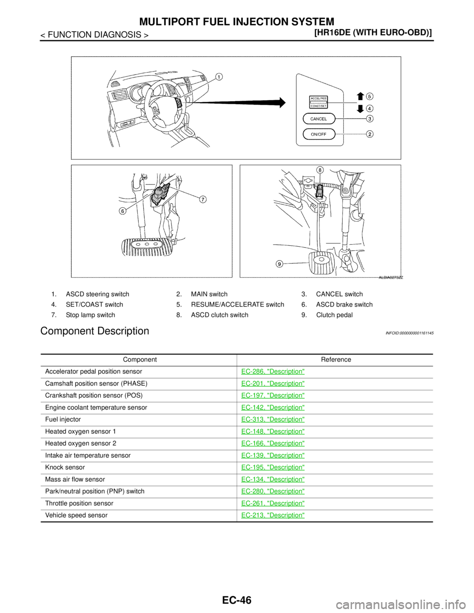
Component Description
INFOID:0000000001161145
1. ASCD steering switch 2. MAIN switch 3. CANCEL switch
4. SET/COAST switch 5. RESUME/ACCELERATE switch 6. ASCD brake switch
7. Stop lamp switch 8. ASCD clutch switch 9. Clutch pedal
ALBIA0273ZZ
Component Reference
Accelerator pedal position sensorEC-286, "
Description"
Camshaft position sensor (PHASE)EC-201, "Description"
Crankshaft position sensor (POS)EC-197, "Description"
Engine coolant temperature sensorEC-142, "Description"
Fuel injectorEC-313, "Description"
Heated oxygen sensor 1EC-148, "Description"
Heated oxygen sensor 2EC-166, "Description"
Intake air temperature sensorEC-139, "Description"
Knock sensorEC-195, "Description"
Mass air flow sensorEC-134, "Description"
Park/neutral position (PNP) switchEC-280, "Description"
Throttle position sensorEC-261, "Description"
Vehicle speed sensorEC-213, "Description"