wheel torque NISSAN TIIDA 2007 Service Repair Manual
[x] Cancel search | Manufacturer: NISSAN, Model Year: 2007, Model line: TIIDA, Model: NISSAN TIIDA 2007Pages: 5883, PDF Size: 78.95 MB
Page 195 of 5883
PRECAUTIONS
BR-3
< PRECAUTION >
C
D
E
G
H
I
J
K
L
MA
B
BR
N
O
P
PRECAUTION
PRECAUTIONS
Precaution for Supplemental Restraint System (SRS) "AIR BAG" and "SEAT BELT
PRE-TENSIONER"
INFOID:0000000001716907
The Supplemental Restraint System such as “AIR BAG” and “SEAT BELT PRE-TENSIONER”, used along
with a front seat belt, helps to reduce the risk or severity of injury to the driver and front passenger for certain
types of collision. This system includes seat belt switch inputs and dual stage front air bag modules. The SRS
system uses the seat belt switches to determine the front air bag deployment, and may only deploy one front
air bag, depending on the severity of a collision and whether the front occupants are belted or unbelted.
Information necessary to service the system safely is included in the SR and SB section of this Service Man-
ual.
WARNING:
• To avoid rendering the SRS inoperative, which could increase the risk of personal injury or death in
the event of a collision which would result in air bag inflation, all maintenance must be performed by
an authorized NISSAN/INFINITI dealer.
Improper maintenance, including incorrect removal and installation of the SRS, can lead to personal
injury caused by unintentional activation of the system. For removal of Spiral Cable and Air Bag
Module, see the SR section.
Do not use electrical test equipment on any circuit related to the SRS unless instructed to in this
Service Manual. SRS wiring harnesses can be identified by yellow and/or orange harnesses or har-
ness connectors.
Precaution for Brake SystemINFOID:0000000001716908
Refill using recommended brake fluid. Refer to MA-19, "Fluids and Lubricants".
Never reuse drained brake fluid.
Be careful not to splash brake fluid on painted surface of body. If brake fluid is splashed on painted surfaces
of body immediately wipe it off with cloth and then wash it away with water.
To clean or wash all parts of master cylinder, disc brake caliper and wheel cylinder, use new brake fluid.
Never use mineral oils such as gasoline or kerosene. They will ruin rubber parts of the hydraulic system.
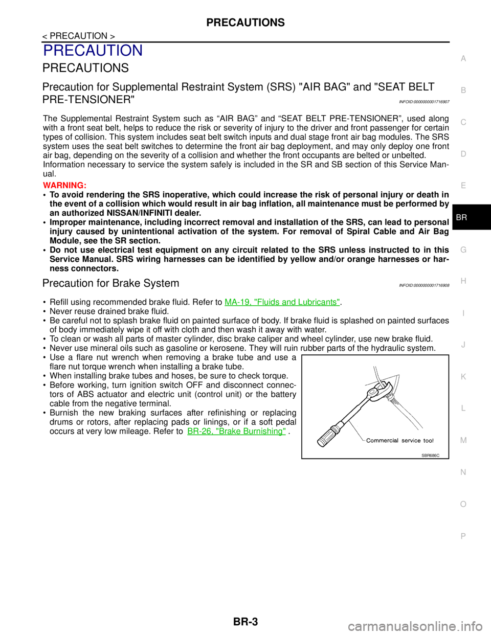
Use a flare nut wrench when removing a brake tube and use a
flare nut torque wrench when installing a brake tube.
When installing brake tubes and hoses, be sure to check torque.
Before working, turn ignition switch OFF and disconnect connec-
tors of ABS actuator and electric unit (control unit) or the battery
cable from the negative terminal.
Burnish the new braking surfaces after refinishing or replacing
drums or rotors, after replacing pads or linings, or if a soft pedal
occurs at very low mileage. Refer toBR-26, "
Brake Burnishing" .
SBR686C
Page 217 of 5883
FRONT DISC BRAKE
BR-25
< ON-VEHICLE REPAIR >
C
D
E
G
H
I
J
K
L
MA
B
BR
N
O
P
2. Remove sliding pin bolt (lower side).
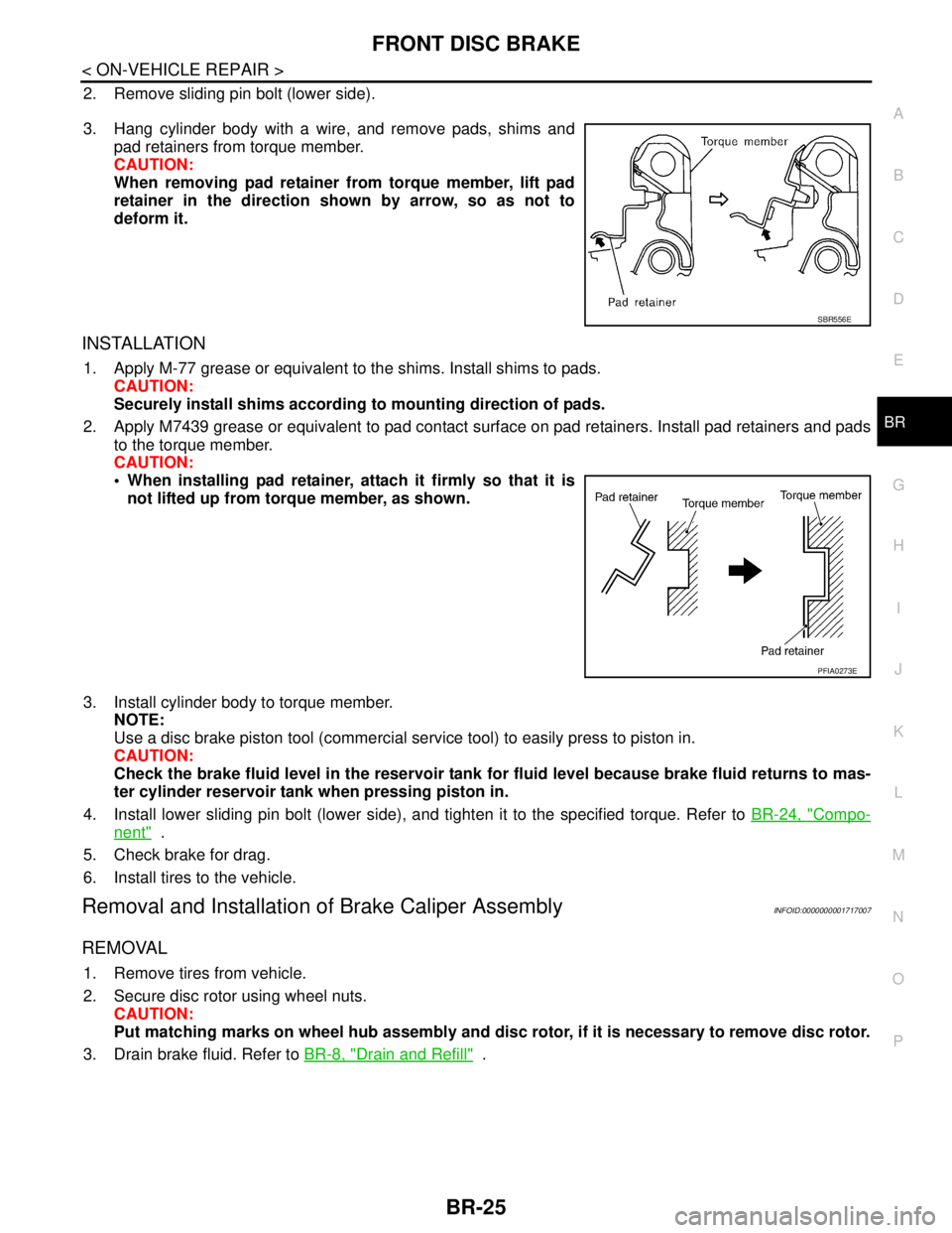
3. Hang cylinder body with a wire, and remove pads, shims and
pad retainers from torque member.
CAUTION:
When removing pad retainer from torque member, lift pad
retainer in the direction shown by arrow, so as not to
deform it.
INSTALLATION
1. Apply M-77 grease or equivalent to the shims. Install shims to pads.
CAUTION:
Securely install shims according to mounting direction of pads.
2. Apply M7439 grease or equivalent to pad contact surface on pad retainers. Install pad retainers and pads
to the torque member.
CAUTION:
When installing pad retainer, attach it firmly so that it is
not lifted up from torque member, as shown.
3. Install cylinder body to torque member.
NOTE:
Use a disc brake piston tool (commercial service tool) to easily press to piston in.
CAUTION:
Check the brake fluid level in the reservoir tank for fluid level because brake fluid returns to mas-
ter cylinder reservoir tank when pressing piston in.
4. Install lower sliding pin bolt (lower side), and tighten it to the specified torque. Refer to BR-24, "
Compo-
nent" .
5. Check brake for drag.
6. Install tires to the vehicle.
Removal and Installation of Brake Caliper AssemblyINFOID:0000000001717007
REMOVAL
1. Remove tires from vehicle.
2. Secure disc rotor using wheel nuts.
CAUTION:
Put matching marks on wheel hub assembly and disc rotor, if it is necessary to remove disc rotor.
3. Drain brake fluid. Refer to BR-8, "
Drain and Refill" .
SBR556E
PFIA0273E
Page 221 of 5883
REAR DISC BRAKE
BR-29
< ON-VEHICLE REPAIR >
C
D
E
G
H
I
J
K
L
MA
B
BR
N
O
P
3. Drain brake fluid. Refer to BR-8, "Bleeding Brake System".
4. Remove connecting bolt and torque member bolts using power tool, and remove cylinder body.
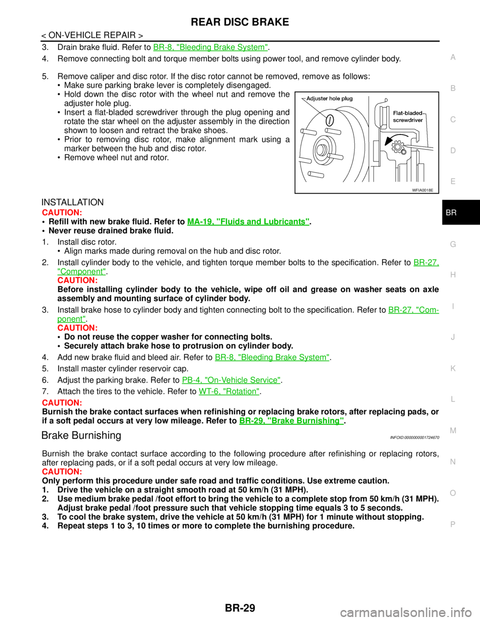
5. Remove caliper and disc rotor. If the disc rotor cannot be removed, remove as follows:
Make sure parking brake lever is completely disengaged.
Hold down the disc rotor with the wheel nut and remove the
adjuster hole plug.
Insert a flat-bladed screwdriver through the plug opening and
rotate the star wheel on the adjuster assembly in the direction
shown to loosen and retract the brake shoes.
Prior to removing disc rotor, make alignment mark using a
marker between the hub and disc rotor.
Remove wheel nut and rotor.
INSTALLATION
CAUTION:
Refill with new brake fluid. Refer to MA-19, "
Fluids and Lubricants".
Never reuse drained brake fluid.
1. Install disc rotor.
Align marks made during removal on the hub and disc rotor.
2. Install cylinder body to the vehicle, and tighten torque member bolts to the specification. Refer to BR-27,
"Component".
CAUTION:
Before installing cylinder body to the vehicle, wipe off oil and grease on washer seats on axle
assembly and mounting surface of cylinder body.
3. Install brake hose to cylinder body and tighten connecting bolt to the specification. Refer to BR-27, "
Com-
ponent".
CAUTION:
Do not reuse the copper washer for connecting bolts.
Securely attach brake hose to protrusion on cylinder body.
4. Add new brake fluid and bleed air. Refer to BR-8, "
Bleeding Brake System".
5. Install master cylinder reservoir cap.
6. Adjust the parking brake. Refer to PB-4, "
On-Vehicle Service".
7. Attach the tires to the vehicle. Refer to WT-6, "
Rotation".
CAUTION:
Burnish the brake contact surfaces when refinishing or replacing brake rotors, after replacing pads, or
if a soft pedal occurs at very low mileage. Refer to BR-29, "
Brake Burnishing".
Brake BurnishingINFOID:0000000001724670
Burnish the brake contact surface according to the following procedure after refinishing or replacing rotors,
after replacing pads, or if a soft pedal occurs at very low mileage.
CAUTION:
Only perform this procedure under safe road and traffic conditions. Use extreme caution.
1. Drive the vehicle on a straight smooth road at 50 km/h (31 MPH).
2. Use medium brake pedal /foot effort to bring the vehicle to a complete stop from 50 km/h (31 MPH).
Adjust brake pedal /foot pressure such that vehicle stopping time equals 3 to 5 seconds.
3. To cool the brake system, drive the vehicle at 50 km/h (31 MPH) for 1 minute without stopping.
4. Repeat steps 1 to 3, 10 times or more to complete the burnishing procedure.
WFIA0018E
Page 227 of 5883
FRONT DISC BRAKE
BR-35
< DISASSEMBLY AND ASSEMBLY >
C
D
E
G
H
I
J
K
L
MA
B
BR
N
O
P
Check sliding pins, sliding pin bolts and sliding pin boots for wear, damage, and cracks. Replace applicable
part as necessary.
ASSEMBLY
CAUTION:
When assembling, use only specified rubber lubricant.
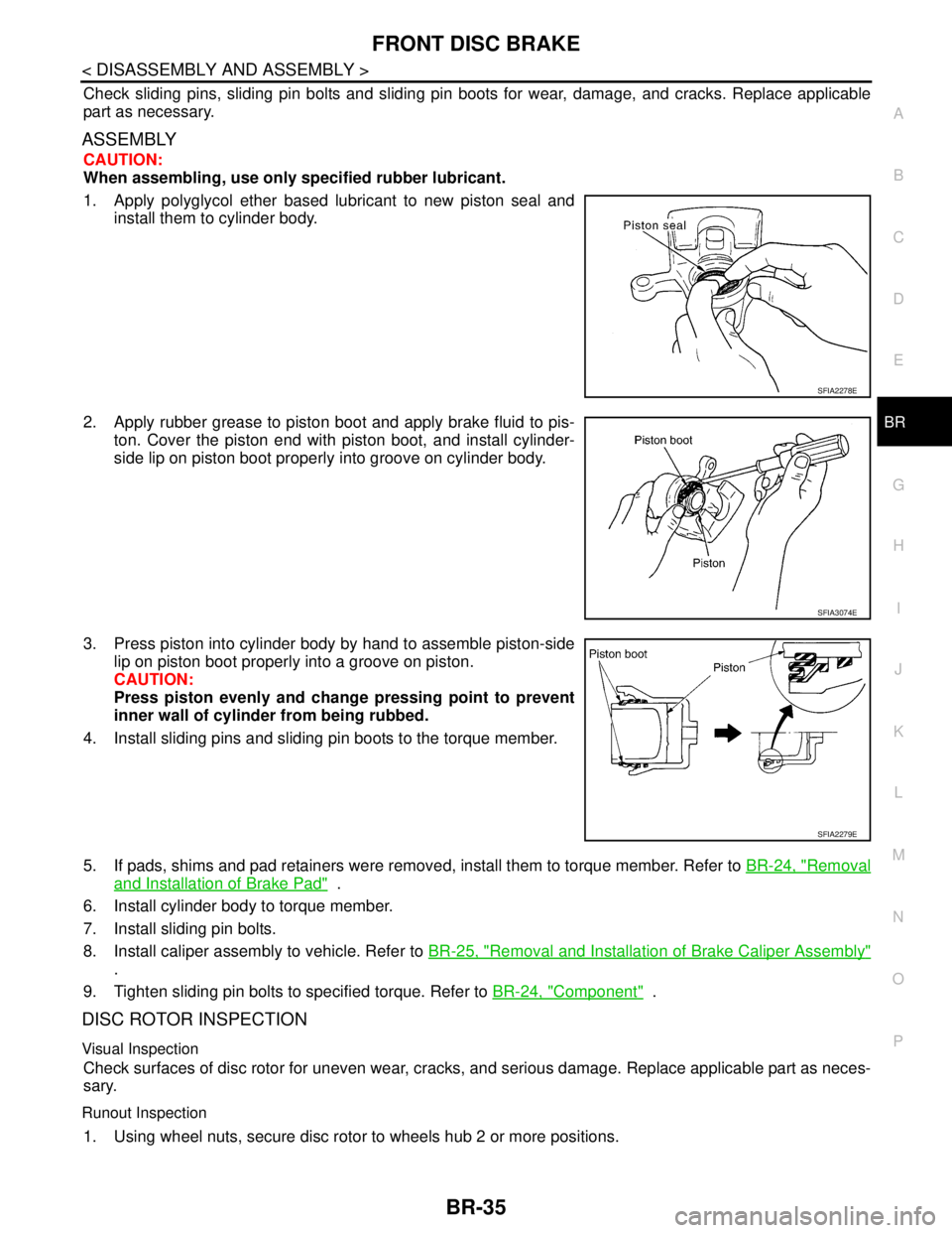
1. Apply polyglycol ether based lubricant to new piston seal and
install them to cylinder body.
2. Apply rubber grease to piston boot and apply brake fluid to pis-
ton. Cover the piston end with piston boot, and install cylinder-
side lip on piston boot properly into groove on cylinder body.
3. Press piston into cylinder body by hand to assemble piston-side
lip on piston boot properly into a groove on piston.
CAUTION:
Press piston evenly and change pressing point to prevent
inner wall of cylinder from being rubbed.
4. Install sliding pins and sliding pin boots to the torque member.
5. If pads, shims and pad retainers were removed, install them to torque member. Refer to BR-24, "
Removal
and Installation of Brake Pad" .
6. Install cylinder body to torque member.
7. Install sliding pin bolts.
8. Install caliper assembly to vehicle. Refer to BR-25, "
Removal and Installation of Brake Caliper Assembly"
.
9. Tighten sliding pin bolts to specified torque. Refer to BR-24, "
Component" .
DISC ROTOR INSPECTION
Visual Inspection
Check surfaces of disc rotor for uneven wear, cracks, and serious damage. Replace applicable part as neces-
sary.
Runout Inspection
1. Using wheel nuts, secure disc rotor to wheels hub 2 or more positions.
SFIA2278E
SFIA3074E
SFIA2279E
Page 231 of 5883
REAR DISC BRAKE
BR-39
< DISASSEMBLY AND ASSEMBLY >
C
D
E
G
H
I
J
K
L
MA
B
BR
N
O
P
5. Attach the sliding pin bolt and sliding pin boot to the torque member.
6. Apply PBC (Poly Butyl Cuprysil) grease or silicone-based grease to the rear of the pad and to both sides
of the shim, and attach the inner shim and shim cover to the inner pad, and the outer shim and outer shim
cover to the outer pad.
7. Attach the pad retainer and pad to the torque member.
CAUTION:
When attaching the pad retainer, attach it firmly so that it
does not float up higher than the torque member, as shown
in the figure.
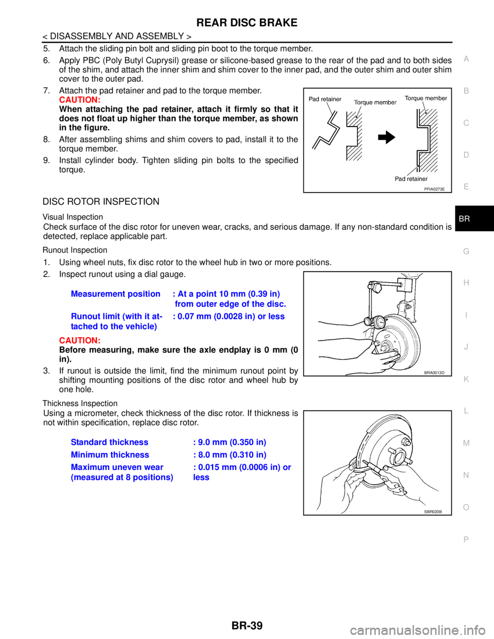
8. After assembling shims and shim covers to pad, install it to the
torque member.
9. Install cylinder body. Tighten sliding pin bolts to the specified
torque.
DISC ROTOR INSPECTION
Visual Inspection
Check surface of the disc rotor for uneven wear, cracks, and serious damage. If any non-standard condition is
detected, replace applicable part.
Runout Inspection
1. Using wheel nuts, fix disc rotor to the wheel hub in two or more positions.
2. Inspect runout using a dial gauge.
CAUTION:
Before measuring, make sure the axle endplay is 0 mm (0
in).
3. If runout is outside the limit, find the minimum runout point by
shifting mounting positions of the disc rotor and wheel hub by
one hole.
Thickness Inspection
Using a micrometer, check thickness of the disc rotor. If thickness is
not within specification, replace disc rotor.
PFIA0273E
Measurement position : At a point 10 mm (0.39 in)
from outer edge of the disc.
Runout limit (with it at-
tached to the vehicle): 0.07 mm (0.0028 in) or less
BRA0013D
Standard thickness : 9.0 mm (0.350 in)
Minimum thickness : 8.0 mm (0.310 in)
Maximum uneven wear
(measured at 8 positions): 0.015 mm (0.0006 in) or
less
SBR020B
Page 249 of 5883
![NISSAN TIIDA 2007 Service Repair Manual BRC-16
< FUNCTION DIAGNOSIS >[ABS]
TCS
TCS
System DiagramINFOID:0000000001731212
System DescriptionINFOID:0000000001731213
Traction Control System is a function that electronically controls engine t NISSAN TIIDA 2007 Service Repair Manual BRC-16
< FUNCTION DIAGNOSIS >[ABS]
TCS
TCS
System DiagramINFOID:0000000001731212
System DescriptionINFOID:0000000001731213
Traction Control System is a function that electronically controls engine t](/img/5/57395/w960_57395-248.png)
BRC-16
< FUNCTION DIAGNOSIS >[ABS]
TCS
TCS
System DiagramINFOID:0000000001731212
System DescriptionINFOID:0000000001731213
Traction Control System is a function that electronically controls engine torque, brake fluid pressure and A/T
gear position to ensure the optimum slippage ratio at drive wheels by computing wheel speed signals from 4
wheel sensors. When ABS actuator and electric unit (control unit) detects a spin at drive wheels (rear
wheels), it compares wheel speed signals from all 4 wheels. At this time, LH and RH rear brake fluid pres-
sure are controlled, while fuel being cut to engine and throttle valve being closed to reduce engine torque by
the control unit. Further more, throttle position is continuously controlled to ensure the optimum engine
torque at all times.
During TCS operation, it informs driver of system operation by flashing SLIP indicator lamp.
Electrical system diagnosis by CONSULT-III is available.
AWFIA0012GB
Page 316 of 5883
![NISSAN TIIDA 2007 Service Repair Manual WHEEL SENSORS
BRC-83
< REMOVAL AND INSTALLATION >[ABS]
C
D
E
G
H
I
J
K
L
MA
B
BRC
N
O
P
REMOVAL AND INSTALLATION
WHEEL SENSORS
Removal and InstallationINFOID:0000000001691408
REMOVAL
Be careful of the NISSAN TIIDA 2007 Service Repair Manual WHEEL SENSORS
BRC-83
< REMOVAL AND INSTALLATION >[ABS]
C
D
E
G
H
I
J
K
L
MA
B
BRC
N
O
P
REMOVAL AND INSTALLATION
WHEEL SENSORS
Removal and InstallationINFOID:0000000001691408
REMOVAL
Be careful of the](/img/5/57395/w960_57395-315.png)
WHEEL SENSORS
BRC-83
< REMOVAL AND INSTALLATION >[ABS]
C
D
E
G
H
I
J
K
L
MA
B
BRC
N
O
P
REMOVAL AND INSTALLATION
WHEEL SENSORS
Removal and InstallationINFOID:0000000001691408
REMOVAL
Be careful of the following.
CAUTION:
When removing the sensor, do not rotate it if possible, and not forcibly pull the sensor harness.
Before removing front or rear wheel hub, remove wheel sensor to avoid sensor wiring damage.
INSTALLATION
Be certain to tighten bolts to the specified torque. Be careful of the following:
Check the inside of the sensor mounting hole for foreign material, the rotor surface for iron chips and other
foreign material, and if anything is non-standard, clean it before installation, or replace it.
When installing the front sensor, completely push in the strut bracket and body bracket rubber grommets
until they lock so that the sensor harness does not become twisted. In addition, there should be no twists in
the harness when installed. Install the harness so that the painted part faces the outside of the vehicle.
When installing the rear sensor, completely push in the rubber bracket of the suspension arm bracket and
lock the marking area of the side member harness mount so that the sensor harness will not be twisted. In
addition, there should be no twists in the harness when installed.
MFIB9029E
Page 329 of 5883
![NISSAN TIIDA 2007 Service Repair Manual BRC-96
< FUNCTION DIAGNOSIS >[ESP/TCS/ABS]
TCS
TCS
System DiagramINFOID:0000000001731069
System DescriptionINFOID:0000000001731070
Traction Control System is a function that electronically controls NISSAN TIIDA 2007 Service Repair Manual BRC-96
< FUNCTION DIAGNOSIS >[ESP/TCS/ABS]
TCS
TCS
System DiagramINFOID:0000000001731069
System DescriptionINFOID:0000000001731070
Traction Control System is a function that electronically controls](/img/5/57395/w960_57395-328.png)
BRC-96
< FUNCTION DIAGNOSIS >[ESP/TCS/ABS]
TCS
TCS
System DiagramINFOID:0000000001731069
System DescriptionINFOID:0000000001731070
Traction Control System is a function that electronically controls engine torque, brake fluid pressure and A/T
gear position to ensure the optimum slippage ratio at drive wheels by computing wheel speed signals from 4
wheel sensors. When ABS actuator and electric unit (control unit) detects a spin at drive wheels (rear
wheels), it compares wheel speed signals from all 4 wheels. At this time, LH and RH rear brake fluid pres-
sure are controlled, while fuel being cut to engine and throttle valve being closed to reduce engine torque by
the control unit. Further more, throttle position is continuously controlled to ensure the optimum engine
torque at all times.
During TCS operation, it informs driver of system operation by flashing SLIP indicator lamp.
Electrical system diagnosis by CONSULT-III is available.
AWFIA0012GB
Page 415 of 5883
![NISSAN TIIDA 2007 Service Repair Manual BRC-182
< REMOVAL AND INSTALLATION >[ESP/TCS/ABS]
WHEEL SENSORS
REMOVAL AND INSTALLATION
WHEEL SENSORS
Removal and InstallationINFOID:0000000001691451
REMOVAL
Be careful of the following.
CAUTION:
W NISSAN TIIDA 2007 Service Repair Manual BRC-182
< REMOVAL AND INSTALLATION >[ESP/TCS/ABS]
WHEEL SENSORS
REMOVAL AND INSTALLATION
WHEEL SENSORS
Removal and InstallationINFOID:0000000001691451
REMOVAL
Be careful of the following.
CAUTION:
W](/img/5/57395/w960_57395-414.png)
BRC-182
< REMOVAL AND INSTALLATION >[ESP/TCS/ABS]
WHEEL SENSORS
REMOVAL AND INSTALLATION
WHEEL SENSORS
Removal and InstallationINFOID:0000000001691451
REMOVAL
Be careful of the following.
CAUTION:
When removing the sensor, do not rotate it if possible, and not forcibly pull the sensor harness.
Before removing front or rear wheel hub, remove wheel sensor to avoid sensor wiring damage.
INSTALLATION
Be certain to tighten bolts to the specified torque. Be careful of the following: Check the inside of the sensor mounting hole for foreign material, the rotor surface for iron chips and other
foreign material, and if anything is non-standard, clean it before installation, or replace it.
When installing the front sensor, completely push in the strut bracket and body bracket rubber grommets
until they lock so that the sensor harness does not become twisted. In addition, there should be no twists in
the harness when installed. Install the harness so that the painted part faces the outside of the vehicle.
When installing the rear sensor, completely push in the rubber bracket of the suspension arm bracket and
lock the marking area of the side member harness mount so that the sensor harness will not be twisted. In
addition, there should be no twists in the harness when installed.
MFIB9030E
Page 2413 of 5883
![NISSAN TIIDA 2007 Service Repair Manual EC-1064
< FUNCTION DIAGNOSIS >[K9K]
FUEL INJECTION CONTROL
energy returned by the piezo actuator is reused, which keeps down the amount of energy that has to be sup-
plied for the next injection proce NISSAN TIIDA 2007 Service Repair Manual EC-1064
< FUNCTION DIAGNOSIS >[K9K]
FUEL INJECTION CONTROL
energy returned by the piezo actuator is reused, which keeps down the amount of energy that has to be sup-
plied for the next injection proce](/img/5/57395/w960_57395-2412.png)
EC-1064
< FUNCTION DIAGNOSIS >[K9K]
FUEL INJECTION CONTROL
energy returned by the piezo actuator is reused, which keeps down the amount of energy that has to be sup-
plied for the next injection process.
Engine Synchronisation
One of the determining factors for fuel injection control is knowing the position of each of the pistons in their
respective cylinders at all times.
The angular position is measured by means of a magneto-inductive sensor which is excited by the teeth
machined onto the flywheel; this is known as the crankshaft position sensor. The flywheel has 60 teeth, each 6
degrees apart; 2 of these teeth are missing to form a notch.
A second sensor (Hall-effect sensor), stimulated by a tooth machined onto the camshaft, which turns at half
the engine speed, provides a signal relating to the progress of the injection cycle. Indeed, when the piston of
cylinder 1 is at top dead centre (TDC), either at the end of the compression stroke or at the end of the exhaust
stroke, the camshaft position sensor enables a distinction to be made between these two states.
By comparing the signals from these two sensors, the computer is able to provide all its systems with synchro-
nisation parameters, namely: the angular position of the flywheel, engine speed, the number of the active fuel
injector and the progress of the injection cycle.
This module also supplies the system with the rotation speed signal.
The camshaft position sensor is only used when starting the engine. As soon as the engine is running by itself
(not being cranked by the starter), the signal provided by the crankshaft position sensor is sufficient. If the
camshaft position sensor should fail while the engine is running, this will not affect the operation of the engine.
Quantity of Fuel Injected and Control of Start of Injection
The parameters for controlling injection are, for each cylinder, the quantity to be injected and the start of
injection. These are calculated by the ECM from the following information:
- Engine speed.
- Accelerator pedal position.
- Turbocharge air pressure.
- Engine coolant temperature.
- Intake air temperature.
- Fuel pump temperature.
- Mass air flow.
- Pressure of fuel in the rail.
Station to Station Flow Regulation
The aim of this regulation process is to facilitate smooth engine operation by compensating for the system
variations (fuel injectors, compression rate, etc.) which affect the torque generated by each cylinder during
combustion.
The regulation process is only active at idle speed, with a warm engine and on condition that the engine speed
is sufficiently stable. An injection timing correction coefficient is assigned to each cylinder; this is "learning" all
the time the regulation process is active and remains fixed at the last value that was learned when the regula-
tion is inactive.
At each new cycle, the coefficients are initialised to 1.
Cylinder Balancing Control
This controller allows smooth behavior of running engine, reduction of noise and oscillations in the drivetrain
by compensating for system dispersions (fuel injectors, compression ratio, manufacturing tolerances of cylin-
ders or valves...) having an influence on the torque generated by each cylinder during combustion.
The controller is only activated if engine is in idle, warm and not too rough. Corrective coefficient on the injec-
tion time is associated with each cylinder that is learnt as soon as the regulation is active. Otherwise it remains
with its last memorized value.
At each new driving cycle, coefficients are initialized to 1.