tires NISSAN TIIDA 2007 Service Repair Manual
[x] Cancel search | Manufacturer: NISSAN, Model Year: 2007, Model line: TIIDA, Model: NISSAN TIIDA 2007Pages: 5883, PDF Size: 78.95 MB
Page 1 of 5883
MODEL C11 SERIES
2007 NISSAN EUROPE S.A.S.
All rights reserved. No part of this Electronic Service Manual may be reproduced or stored in a retrieval system, or transmitted in any form,
or by any means, electronic, mechanical, photocopying, recording or otherwise, without the prior written permission of Nissan Europe
S.A.S., Paris, France.
A GENERAL INFORMATION
B ENGINE
D TRANSMISSION& DRIVELINE
E SUSPENSION F BRAKES
G STEERING H RESTRAINTS
I VENTILATION, HEATER & AIR CONDITIONER
J BODY INTERIOR
K BODY EXTERIOR, DOOR, ROOF & VEHICLE SECURITY
L DRIVER CONTROLS
M ELECTRICAL & POWER CONTROL
N DRIVER INFORMATION & MULTIMEDIA
O CRUISE CONTROL P MAINTENANCEGI General Information
EM Engine Mechanical
LU Engine Lubrication System
CO Engine Cooling System
EC Engine Control System
FL Fuel System
EX Exhaust System
STR Starting System
ACC Accelerator Control System
CL Clutch
TM Transaxle & Transmission
FAX Front Axle
RAX Rear Axle
FSU Front Suspension
RSU Rear Suspension
WT Road Wheels & Tires
BR Brake System
PB Parking Brake System
BRC Brake Control System
ST Steering System
STC Steering Control System
SB Seat Belt
SR SRS Airbag
SRC SRS Airbag Control System
VTL Ventilation System
HA Heater & Air Conditioning System
HAC Heater & Air Conditioning Control System
INT Interior
IP Instrument Panel
SE Seat
DLK Door & Lock
SEC Security Control System
GW Glass & Window System
PWC Power Window Control System
RF Roof
EXT Exterior
MIR Mirrors
EXL Exterior Lighting System
INL Interior Lighting System
WW Wiper & Washer
DEF Defogger
HRN Horn
PWO Power Outlet
BCS Body Control System
LAN LAN System
PCS Power Control System
CHG Charging System
PG Power Supply, Ground & Circuit Elements
MWI Meter, Warning Lanp & Indicator
WCS Warning Chime System
AV Audio, Visual & Navigation System
CCS Cruise Control System Maintenance
MA Maintenance
QUICK REFERENCE INDEX
A
B
C
D
E
F
G
H
I
J
K
L
M
N
O
P
M
Publication Number:
SM7E00-1C11E0E
Page 40 of 5883
![NISSAN TIIDA 2007 Service Repair Manual AV
NAVIGATION SYSTEM
AV-35
< FUNCTION DIAGNOSIS >[AUDIO WITH NAVIGATION]
C
D
E
F
G
H
I
J
K
L
MB A
O
P
NAVIGATION SYSTEM
System DiagramINFOID:0000000001728631
System DescriptionINFOID:0000000001728632
NISSAN TIIDA 2007 Service Repair Manual AV
NAVIGATION SYSTEM
AV-35
< FUNCTION DIAGNOSIS >[AUDIO WITH NAVIGATION]
C
D
E
F
G
H
I
J
K
L
MB A
O
P
NAVIGATION SYSTEM
System DiagramINFOID:0000000001728631
System DescriptionINFOID:0000000001728632](/img/5/57395/w960_57395-39.png)
AV
NAVIGATION SYSTEM
AV-35
< FUNCTION DIAGNOSIS >[AUDIO WITH NAVIGATION]
C
D
E
F
G
H
I
J
K
L
MB A
O
P
NAVIGATION SYSTEM
System DiagramINFOID:0000000001728631
System DescriptionINFOID:0000000001728632
NAVIGATION SYSTEM
Location Detection Principle
The navigation system periodically calculates the vehicle's current
position according to the following three signals:
Travel distance of the vehicle as determined by the vehicle speed
sensor
Turning angle of the vehicle as determined by the gyroscope
(angular velocity sensor)
Direction of vehicle travel as determined by the GPS antenna
(GPS information)
The current position of the vehicle is then identified by comparing the
calculated vehicle position with map data read from the map DVD-
ROM, which is stored in the DVD-ROM drive (map-matching), and
indicated on the screen as a vehicle mark. More accurate data is
judged and used by comparing vehicle position detection results found by the GPS with the result by map-
matching.
The current vehicle position will be calculated by detecting the dis-
tance the vehicle moved from the previous calculation point and its
direction.
Travel distance
Travel distance calculations are based on the vehicle speed sen-
sor input signal. Therefore, the calculation may become incorrect
as the tires wear down. To prevent this, an automatic distance cor-
rection function has been adopted.
Travel direction
Change in the travel direction of the vehicle is calculated by a gyro-
scope (angular velocity sensor) and a GPS antenna (GPS informa-
tion). They have both advantages and disadvantages.
JPNIA0157GB
SKIB1058E
SEL684V
Page 49 of 5883
![NISSAN TIIDA 2007 Service Repair Manual AV-44
< FUNCTION DIAGNOSIS >[AUDIO WITH NAVIGATION]
DIAGNOSIS SYSTEM (NAVI CONTROL UNIT)
Select “SPEAKER TEST” to display the Speaker Diagnosis screen.
Press “START and NEXT” to generate a tes NISSAN TIIDA 2007 Service Repair Manual AV-44
< FUNCTION DIAGNOSIS >[AUDIO WITH NAVIGATION]
DIAGNOSIS SYSTEM (NAVI CONTROL UNIT)
Select “SPEAKER TEST” to display the Speaker Diagnosis screen.
Press “START and NEXT” to generate a tes](/img/5/57395/w960_57395-48.png)
AV-44
< FUNCTION DIAGNOSIS >[AUDIO WITH NAVIGATION]
DIAGNOSIS SYSTEM (NAVI CONTROL UNIT)
Select “SPEAKER TEST” to display the Speaker Diagnosis screen.
Press “START and NEXT” to generate a test tone in a speaker.
Press “Start” to generate a test tone in the next speaker. Press
“Stop” to stop the test tones.
NOTE:
The frequency of test tone emitted from each speaker is as follows.
Navigation
STEERING ANGLE ADJUSTMENT
The steering angle output value detected with the gyroscope is
adjusted.
SPEED CALIBRATION
During normal driving, distance error caused by tire wear and tire
pressure change is automatically adjusted for by the automatic dis-
tance correction function. This function, on the other hand, is for
immediate adjustment, in cases such as driving with tire chain fitted
on tires.
ERROR HISTORY
The diagnostic results of “Self-diagnosis” determine if any malfunction occurred between selecting “Self-diag-
nosis” and displaying “Self-diagnostic Results”.
The trouble diagnosis result will be judged normal if an error occurred before the ignition switch was turned
ON and does not occur again until “Self-diagnosis” is completed. Therefore, errors in the past which cannot be
found by “Self-diagnosis”, must be found by checking the “Error record”.
The error history shows the error occurrence frequency in past. The frequency of occurrence is displayed by 2
types: the count down type and the count up type. Select either type according to the error item.
In “Error History” of models with NAVI, time and place that the selected error last occurred are displayed. Be
careful about the following.
The correct date of occurrence may not be able to be displayed if there is a malfunction with the GPS
antenna circuit board in the NAVI control unit.
Place of the error occurrence is represented by the position of the current location mark at the time an error
occurred. If current location mark has deviated from the correct position, then the place of the error occur-
rence cannot be located correctly.Tweeter : 3 kHz
Front door speaker : 300 Hz
Rear door speaker : 1 kHz
SKIB4686E
SKIB3684E
SKIB3685E
Page 117 of 5883
![NISSAN TIIDA 2007 Service Repair Manual AV-112
< SYMPTOM DIAGNOSIS >[AUDIO WITH NAVIGATION]
NORMAL OPERATING CONDITION
MAP DVD-ROM
ROUTE CALCULATION AND VISUAL GUIDANCE
The GPS indicator on the screen
remains gray.GPS signals cannot be rec NISSAN TIIDA 2007 Service Repair Manual AV-112
< SYMPTOM DIAGNOSIS >[AUDIO WITH NAVIGATION]
NORMAL OPERATING CONDITION
MAP DVD-ROM
ROUTE CALCULATION AND VISUAL GUIDANCE
The GPS indicator on the screen
remains gray.GPS signals cannot be rec](/img/5/57395/w960_57395-116.png)
AV-112
< SYMPTOM DIAGNOSIS >[AUDIO WITH NAVIGATION]
NORMAL OPERATING CONDITION
MAP DVD-ROM
ROUTE CALCULATION AND VISUAL GUIDANCE
The GPS indicator on the screen
remains gray.GPS signals cannot be received depending on the
vehicle location, such as in a parking garage, on a
road that has numerous tall buildings, etc.Drive on an open, straight road for a while.
GPS signals cannot be received because objects are
placed on top of the display.Remove the objects from top of the dis-
play.
A sufficient amount of GPS satellites are not avail-
able.Wait for the satellites to move locations
available for navigation system.
The location of vehicle icon is mis-
aligned from the actual position.Speed calculations based on the speed sensor may
be incorrect when using tire chains or replacing the
tires.Drive the vehicle for a while (at approxi-
mately 30 km/h (19 MPH) for about 30
minutes) to automatically correct the vehi-
cle icon position.
Contact an NISSAN / INFINITI dealer if
this does not correct the vehicle icon posi-
tion.
The map data has mistake or is incomplete (the vehi-
cle icon position is always misaligned in the same ar-
ea).Updated road information will be included
in the next version of the map DVD-ROM. Symptoms Possible cause Possible solution
Symptom Possible cause Possible solution
The message “Error” appears. Map DVD-ROM is dirty or partially damaged.Check the DVD-ROM and wipe it clean
with a soft cloth.
Replace the DVD-ROM if there is any
damage.
Symptoms Possible cause Possible solution
In the auto reroute calculation, way-
points are not included.Waypoints already passed are not included in the
auto reroute calculation.In case of going to that waypoints again,
edit the route.
Route information is not displayed.Route calculation has not yet been performed.Set the destination and perform route calcu-
lation.
The vehicle is not driven on the suggested route. Drive on the suggested route.
Route guidance is set to off. Turn on route guidance.
Route information is not provided for narrow streets
(roads displayed in gray).This is not a malfunction.
The auto reroute calculation (or de-
tour calculation) suggests the same
route as the one previously sug-
gested. Route calculation took priority conditions into con-
sideration, but the same route was calculated. This is not a malfunction.
A waypoint cannot be added.Five waypoints are already set on the route, includ-
ing ones that already passed.A maximum of 5 waypoints can be set on
the route. In case of going to 6 or more way-
points, perform route calculations multiple
times as necessary.
The suggested route is not dis-
played.Roads near the destination cannot be calculated.Reset the destination to a main or ordinary
road, and recalculate the route.
The starting point and destination are too close. Set a more distant destination.
The starting point and destination are too far away.Divide the way by selecting one or two inter-
mediate destinations, and perform route
calculations multiple times.
There are time restricted roads (by day of week, by
time) near the current vehicle location or destina-
tion.Set Use Time Restricted Roads to off.
A part of the route is not displayed.The suggested route includes narrow streets (roads
displayed in gray).This is not a malfunction.
Page 121 of 5883
![NISSAN TIIDA 2007 Service Repair Manual AV-116
< SYMPTOM DIAGNOSIS >[AUDIO WITH NAVIGATION]
NORMAL OPERATING CONDITION
PlaceIn a parking lotMatching may place the vehicle
mark on a nearby road when driving
in a parking lot, or other locat NISSAN TIIDA 2007 Service Repair Manual AV-116
< SYMPTOM DIAGNOSIS >[AUDIO WITH NAVIGATION]
NORMAL OPERATING CONDITION
PlaceIn a parking lotMatching may place the vehicle
mark on a nearby road when driving
in a parking lot, or other locat](/img/5/57395/w960_57395-120.png)
AV-116
< SYMPTOM DIAGNOSIS >[AUDIO WITH NAVIGATION]
NORMAL OPERATING CONDITION
PlaceIn a parking lotMatching may place the vehicle
mark on a nearby road when driving
in a parking lot, or other locations
where there are no roads on the
map. The vehicle mark may have
deviated from the correct location
when the vehicle returns to the road.
Direction errors accumulate, and the
vehicle mark may deviate from the
correct location when driving in cir-
cle or turning the steering wheel re-
peatedly.
Perform location correction and, if
necessary, direction correction if the
correct location has not been re-
stored after traveling about 10 km/h
(6 MPH). TurntableThe navigation system cannot re-
ceive the signal from the gyroscope
(angular speed sensor) when the ig-
nition switch is OFF. Therefore, the
displayed direction may be incorrect
and the correct road may not be eas-
ily returned to after rotating the vehi-
cle on a turntable with the ignition
OFF.
Slippery roadsOn snow, wet roads, gravel, or other
roads where tires may slip easily, ac-
cumulated mileage errors may
cause the vehicle mark to deviate
from the correct road.
SlopesAn error in the turning angle will oc-
cur, and the vehicle mark may devi-
ate from the road when parking in
sloped garages, when traveling on
banked roads, or in other cases
where the vehicle turns when tilted.
Map dataRoads not displayed on the map screen
Map matching does not function cor-
rectly and matches the location to a
nearby road when driving on new
roads or other roads not displayed
on the map screen. The vehicle
mark may deviate from the correct
road when the vehicle returns to a
road which is on the map.
Different road pattern
(Changed due to repair)
Map matching does not function cor-
rectly and matches the location to a
nearby road if the road pattern
stored in the map data and the actu-
al road pattern are different. The ve-
hicle mark may deviate from the
correct road. Cause (condition) Driving condition Remarks (correction, etc.)
SEL709V
SEL710V
SEL699V
ELK0201D
Page 122 of 5883
![NISSAN TIIDA 2007 Service Repair Manual AV
NORMAL OPERATING CONDITION
AV-117
< SYMPTOM DIAGNOSIS >[AUDIO WITH NAVIGATION]
C
D
E
F
G
H
I
J
K
L
MB A
O
P
THE CURRENT POSITION MARK SHOWS A POSITION THAT IS COMPLETELY INCORRECT.
In the following NISSAN TIIDA 2007 Service Repair Manual AV
NORMAL OPERATING CONDITION
AV-117
< SYMPTOM DIAGNOSIS >[AUDIO WITH NAVIGATION]
C
D
E
F
G
H
I
J
K
L
MB A
O
P
THE CURRENT POSITION MARK SHOWS A POSITION THAT IS COMPLETELY INCORRECT.
In the following](/img/5/57395/w960_57395-121.png)
AV
NORMAL OPERATING CONDITION
AV-117
< SYMPTOM DIAGNOSIS >[AUDIO WITH NAVIGATION]
C
D
E
F
G
H
I
J
K
L
MB A
O
P
THE CURRENT POSITION MARK SHOWS A POSITION THAT IS COMPLETELY INCORRECT.
In the following cases, the current location mark may be displayed in a completely incorrect location. If so, per-
form position/direction correction.
When location correction has not been done
- It may shift to a completely unexpected location and not return unless location correction is performed if
GPS satellite reception is poor and the current location mark slips out of place. The position will be corrected
if a GPS signal can be received.
When vehicle is traveled by ferry, or when vehicle is towed.
- Because calculation of the current location cannot be done when traveling with the ignition OFF, for example
when traveling by ferry or when being towed, the location before travel is displayed. The location will be cor-
rected if the precise location can be detected with GPS.
Ve h i c l eUse of tire chains
The vehicle mark may deviate from
the correct road.Drive the vehicle for a while. Adjust
it with the distance adjustment func-
tion if distance still deviates. (Re-
cover the original value if tire chains
are removed.)
Use of tires other than the specified sizeReplace all tires with the specified
size tire.
Malfunctioning air pressure of tireAdjust all tires to the specified air
pressure.
Replace tireDrive the vehicle for a while. It ad-
justs with the distance adjustment
function if the distance is still not in
the correct location.
Driving man-
nerJust after the engine is startedThe vehicle can be shown in the in-
correct direction and may deviate
from the correct location if vehicle is
driven off just after the engine is
started when gyroscope (angular
speed sensor) correction is not com-
pleted.Wait for a short while before driving
after starting the engine.
Continuous driving without stoppingDirection errors may accumulate,
and the current location mark may
deviate from the correct road when
driving long distances without stop-
ping.Stop and adjust orientation.
Abusive drivingSpinning the wheels or engaging in
other kinds of abusive driving may
result in the system being unable
perform correct detection, and may
cause the vehicle mark to deviate
from the correct road.Perform location correction and, if
necessary, direction correction if af-
ter traveling about 10 km/h (6 MPH)
the correct location has not been re-
stored.
Position cor-
rection
methodPosition correction accuracy
Accuracy may be reduced when cor-
rect road cannot be found, particu-
larly in places where there are many
roads if accuracy of location settings
is poor.From the roads displayed on the
screen, input a position within an
accuracy of 1mm (0.04 in).
CAUTION:
When correcting, use the most
detailed map possible.
Direction when location is corrected
Accuracy may be reduced after-
wards if accuracy of location set-
tings during correction is poor.Perform direction correction. Cause (condition) Driving condition Remarks (correction, etc.)
SEL701V
SEL702V
Page 197 of 5883
NOISE, VIBRATION AND HARSHNESS (NVH) TROUBLESHOOTING
BR-5
< SYMPTOM DIAGNOSIS >
C
D
E
G
H
I
J
K
L
MA
B
BR
N
O
P
SYMPTOM DIAGNOSIS
NOISE, VIBRATION AND HARSHNESS (NVH) TROUBLESHOOTING
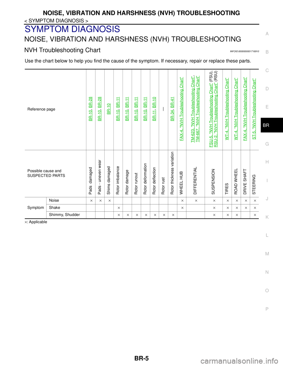
NVH Troubleshooting ChartINFOID:0000000001716910
Use the chart below to help you find the cause of the symptom. If necessary, repair or replace these parts.
×: ApplicableReference page
BR-10
, BR-28
BR-10
, BR-28BR-10
BR-10
, BR-11
BR-10
, BR-11
BR-10
, BR-11
BR-10
, BR-11
BR-11
, BR-10—
BR-34, BR-41
FAX-4, "
NVH Troubleshooting Chart
"
TM-623, "
NVH Troubleshooting Chart
",
TM-667, "
NVH Troubleshooting Chart
"
FSU-5, "
NVH Troubleshooting Chart
" (FSU),
RSU-2, "
NVH Troubleshooting Chart
" (RSU)
WT-4, "
NVH Troubleshooting Chart
"
WT-4, "
NVH Troubleshooting Chart
"
FAX-4, "
NVH Troubleshooting Chart
"
ST-5, "
NVH Troubleshooting Chart
"
Possible cause and
SUSPECTED PARTS
Pads damaged
Pads - uneven wear
Shims damaged
Rotor imbalance
Rotor damage
Rotor runout
Rotor deformation
Rotor deflection
Rotor rust
Rotor thickness variation
WHEEL HUB
DIFFERENTIAL
SUSPENSION
TIRES
ROAD WHEEL
DRIVE SHAFT
STEERING
SymptomNoise××× × × × ××××
Shake×××××××
Shimmy, Shudder××××××× × ×× ×
Page 216 of 5883
BR-24
< ON-VEHICLE REPAIR >
FRONT DISC BRAKE
FRONT DISC BRAKE
ComponentINFOID:0000000001717005
CAUTION:
Clean dust on caliper and brake pad with a vacuum dust collector. Do not blow with compressed air.
While removing brake pad or cylinder body, do not depress brake pedal because piston will pop out.
It is not necessary to remove torque member mounting bolts and brake hose except for disassembly
or replacement of caliper assembly. In this case, hang cylinder body with a wire so that brake hose is
not under tension.
Do not damage piston boot.
If any shim is subject to serious corrosion, replace it with a new one.
Keep rotor free from brake fluid.
When replacing brake pad, replace shim with a new one.
Removal and Installation of Brake PadINFOID:0000000001717006
REMOVAL
1. Remove tires from vehicle.
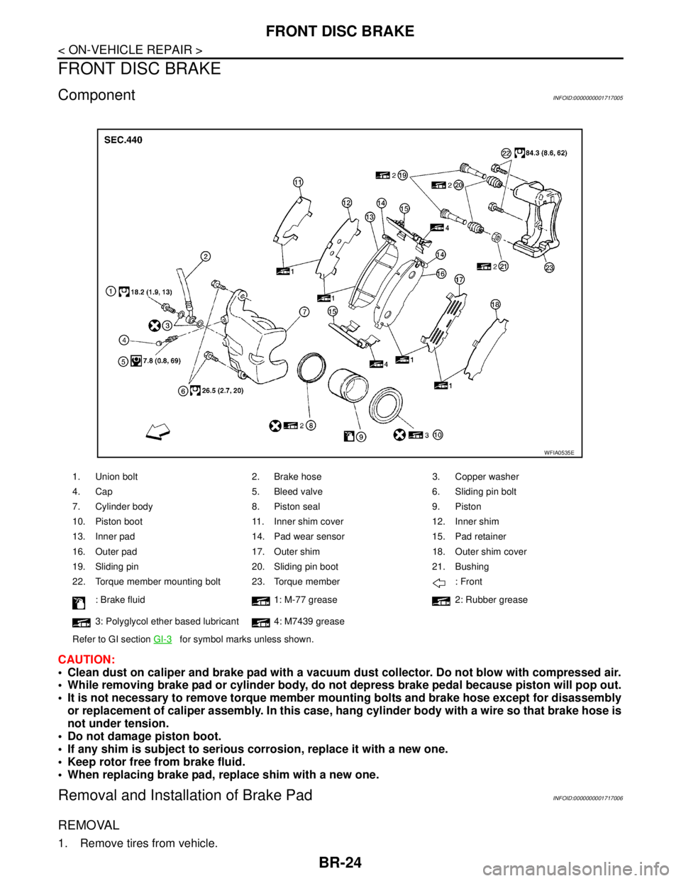
1. Union bolt 2. Brake hose 3. Copper washer
4. Cap 5. Bleed valve 6. Sliding pin bolt
7. Cylinder body 8. Piston seal 9. Piston
10. Piston boot 11. Inner shim cover 12. Inner shim
13. Inner pad 14. Pad wear sensor 15. Pad retainer
16. Outer pad 17. Outer shim 18. Outer shim cover
19. Sliding pin 20. Sliding pin boot 21. Bushing
22. Torque member mounting bolt 23. Torque member : Front
: Brake fluid 1: M-77 grease 2: Rubber grease
3: Polyglycol ether based lubricant 4: M7439 grease
Refer to GI section GI-3
for symbol marks unless shown.
WFIA0535E
Page 217 of 5883
FRONT DISC BRAKE
BR-25
< ON-VEHICLE REPAIR >
C
D
E
G
H
I
J
K
L
MA
B
BR
N
O
P
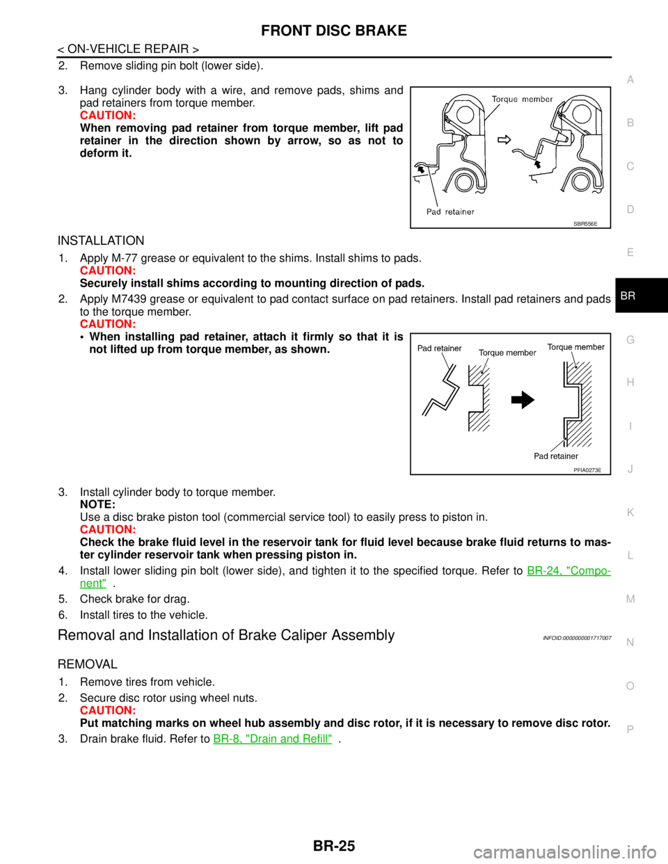
2. Remove sliding pin bolt (lower side).
3. Hang cylinder body with a wire, and remove pads, shims and
pad retainers from torque member.
CAUTION:
When removing pad retainer from torque member, lift pad
retainer in the direction shown by arrow, so as not to
deform it.
INSTALLATION
1. Apply M-77 grease or equivalent to the shims. Install shims to pads.
CAUTION:
Securely install shims according to mounting direction of pads.
2. Apply M7439 grease or equivalent to pad contact surface on pad retainers. Install pad retainers and pads
to the torque member.
CAUTION:
When installing pad retainer, attach it firmly so that it is
not lifted up from torque member, as shown.
3. Install cylinder body to torque member.
NOTE:
Use a disc brake piston tool (commercial service tool) to easily press to piston in.
CAUTION:
Check the brake fluid level in the reservoir tank for fluid level because brake fluid returns to mas-
ter cylinder reservoir tank when pressing piston in.
4. Install lower sliding pin bolt (lower side), and tighten it to the specified torque. Refer to BR-24, "
Compo-
nent" .
5. Check brake for drag.
6. Install tires to the vehicle.
Removal and Installation of Brake Caliper AssemblyINFOID:0000000001717007
REMOVAL
1. Remove tires from vehicle.
2. Secure disc rotor using wheel nuts.
CAUTION:
Put matching marks on wheel hub assembly and disc rotor, if it is necessary to remove disc rotor.
3. Drain brake fluid. Refer to BR-8, "
Drain and Refill" .
SBR556E
PFIA0273E
Page 218 of 5883
BR-26
< ON-VEHICLE REPAIR >
FRONT DISC BRAKE
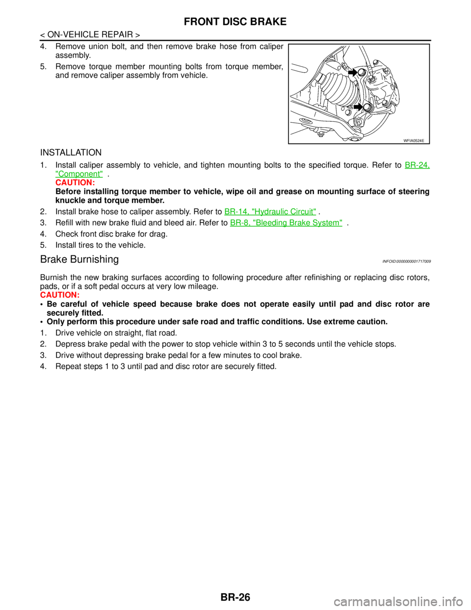
4. Remove union bolt, and then remove brake hose from caliper
assembly.
5. Remove torque member mounting bolts from torque member,
and remove caliper assembly from vehicle.
INSTALLATION
1. Install caliper assembly to vehicle, and tighten mounting bolts to the specified torque. Refer to BR-24,
"Component" .
CAUTION:
Before installing torque member to vehicle, wipe oil and grease on mounting surface of steering
knuckle and torque member.
2. Install brake hose to caliper assembly. Refer to BR-14, "
Hydraulic Circuit" .
3. Refill with new brake fluid and bleed air. Refer to BR-8, "
Bleeding Brake System" .
4. Check front disc brake for drag.
5. Install tires to the vehicle.
Brake BurnishingINFOID:0000000001717009
Burnish the new braking surfaces according to following procedure after refinishing or replacing disc rotors,
pads, or if a soft pedal occurs at very low mileage.
CAUTION:
Be careful of vehicle speed because brake does not operate easily until pad and disc rotor are
securely fitted.
Only perform this procedure under safe road and traffic conditions. Use extreme caution.
1. Drive vehicle on straight, flat road.
2. Depress brake pedal with the power to stop vehicle within 3 to 5 seconds until the vehicle stops.
3. Drive without depressing brake pedal for a few minutes to cool brake.
4. Repeat steps 1 to 3 until pad and disc rotor are securely fitted.
WFIA0524E