wiring NISSAN TIIDA 2007 Service Workshop Manual
[x] Cancel search | Manufacturer: NISSAN, Model Year: 2007, Model line: TIIDA, Model: NISSAN TIIDA 2007Pages: 5883, PDF Size: 78.95 MB
Page 600 of 5883
DLK-11
C
D
E
F
G
H
I
J
L
MA
B
DLK
N
O
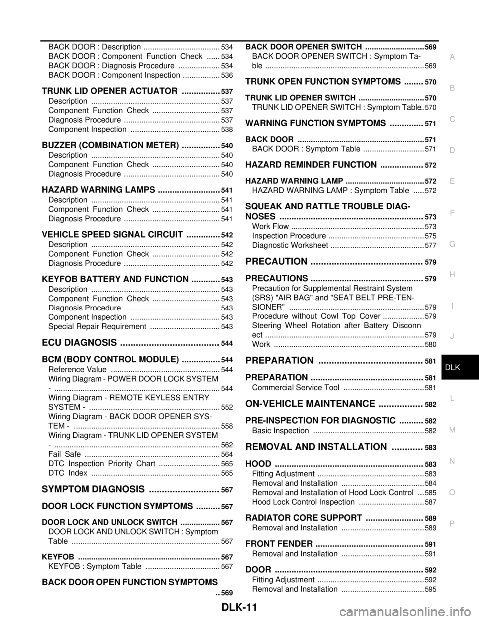
P BACK DOOR : Description ....................................
534
BACK DOOR : Component Function Check .......534
BACK DOOR : Diagnosis Procedure ....................534
BACK DOOR : Component Inspection ..................536
TRUNK LID OPENER ACTUATOR .................537
Description ............................................................537
Component Function Check ................................537
Diagnosis Procedure .............................................537
Component Inspection ..........................................538
BUZZER (COMBINATION METER) .................540
Description ............................................................540
Component Function Check ................................540
Diagnosis Procedure .............................................540
HAZARD WARNING LAMPS ...........................541
Description ............................................................541
Component Function Check ................................541
Diagnosis Procedure .............................................541
VEHICLE SPEED SIGNAL CIRCUIT ...............542
Description ............................................................542
Component Function Check ................................542
Diagnosis Procedure .............................................542
KEYFOB BATTERY AND FUNCTION .............543
Description ............................................................543
Component Function Check ................................543
Diagnosis Procedure .............................................543
Component Inspection ..........................................543
Special Repair Requirement .................................543
ECU DIAGNOSIS .......................................544
BCM (BODY CONTROL MODULE) .................544
Reference Value ...................................................544
Wiring Diagram - POWER DOOR LOCK SYSTEM
- .............................................................................
544
Wiring Diagram - REMOTE KEYLESS ENTRY
SYSTEM - .............................................................
552
Wiring Diagram - BACK DOOR OPENER SYS-
TEM - ....................................................................
558
Wiring Diagram - TRUNK LID OPENER SYSTEM
- .............................................................................
562
Fail Safe ...............................................................564
DTC Inspection Priority Chart .............................565
DTC Index ............................................................565
SYMPTOM DIAGNOSIS ............................567
DOOR LOCK FUNCTION SYMPTOMS ...........567
DOOR LOCK AND UNLOCK SWITCH ...................567
DOOR LOCK AND UNLOCK SWITCH : Symptom
Table .....................................................................
567
KEYFOB ..................................................................567
KEYFOB : Symptom Table ...................................567
BACK DOOR OPEN FUNCTION SYMPTOMS
..
569
BACK DOOR OPENER SWITCH ............................569
BACK DOOR OPENER SWITCH : Symptom Ta-
ble ..........................................................................
569
TRUNK OPEN FUNCTION SYMPTOMS ........570
TRUNK LID OPENER SWITCH ...............................570
TRUNK LID OPENER SWITCH : Symptom Table ..570
WARNING FUNCTION SYMPTOMS ..............571
BACK DOOR ...........................................................571
BACK DOOR : Symptom Table .............................571
HAZARD REMINDER FUNCTION ..................572
HAZARD WARNING LAMP .....................................572
HAZARD WARNING LAMP : Symptom Table ......572
SQUEAK AND RATTLE TROUBLE DIAG-
NOSES ............................................................
573
Work Flow ..............................................................573
Inspection Procedure .............................................575
Diagnostic Worksheet ............................................577
PRECAUTION ............................................579
PRECAUTIONS ...............................................579
Precaution for Supplemental Restraint System
(SRS) "AIR BAG" and "SEAT BELT PRE-TEN-
SIONER" ...............................................................
579
Procedure without Cowl Top Cover ....................579
Steering Wheel Rotation after Battery Disconn
ect ..........................................................................
579
Work ......................................................................580
PREPARATION .........................................581
PREPARATION ...............................................581
Commercial Service Tool ......................................581
ON-VEHICLE MAINTENANCE ..................582
PRE-INSPECTION FOR DIAGNOSTIC ..........582
Basic Inspection ....................................................582
REMOVAL AND INSTALLATION .............583
HOOD ..............................................................583
Fitting Adjustment ..................................................583
Removal and Installation .......................................584
Removal and Installation of Hood Lock Control ....585
Hood Lock Control Inspection ...............................587
RADIATOR CORE SUPPORT ........................589
Removal and Installation .......................................589
FRONT FENDER .............................................591
Removal and Installation .......................................591
DOOR ..............................................................592
Fitting Adjustment ..................................................592
Removal and Installation .......................................595
Page 603 of 5883
DLK-14
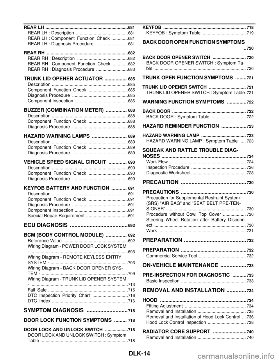
REAR LH ..................................................................681
REAR LH : Description ..........................................681
REAR LH : Component Function Check ..............681
REAR LH : Diagnosis Procedure ...........................681
REAR RH .................................................................682
REAR RH : Description .........................................682
REAR RH : Component Function Check .............682
REAR RH : Diagnosis Procedure ..........................683
TRUNK LID OPENER ACTUATOR .................685
Description .............................................................685
Component Function Check ................................685
Diagnosis Procedure .............................................685
Component Inspection ...........................................686
BUZZER (COMBINATION METER) ................688
Description .............................................................688
Component Function Check ................................688
Diagnosis Procedure .............................................688
HAZARD WARNING LAMPS ..........................689
Description .............................................................689
Component Function Check ................................689
Diagnosis Procedure .............................................689
VEHICLE SPEED SIGNAL CIRCUIT ..............690
Description .............................................................690
Component Function Check ................................690
Diagnosis Procedure .............................................690
KEYFOB BATTERY AND FUNCTION ............691
Description .............................................................691
Component Function Check ................................691
Diagnosis Procedure .............................................691
Component Inspection ...........................................691
Special Repair Requirement ..................................691
ECU DIAGNOSIS .......................................692
BCM (BODY CONTROL MODULE) ................692
Reference Value ....................................................692
Wiring Diagram - POWER DOOR LOCK SYSTEM
- .............................................................................
693
Wiring Diagram - REMOTE KEYLESS ENTRY
SYSTEM - ..............................................................
703
Wiring Diagram - BACK DOOR OPENER SYS-
TEM - .....................................................................
709
Wiring Diagram - TRUNK LID OPENER SYSTEM
- .............................................................................
713
Fail Safe ................................................................715
DTC Inspection Priority Chart .............................716
DTC Index .............................................................716
SYMPTOM DIAGNOSIS ............................718
DOOR LOCK FUNCTION SYMPTOMS ..........718
DOOR LOCK AND UNLOCK SWITCH ...................718
DOOR LOCK AND UNLOCK SWITCH : Symptom
Table ......................................................................
718
KEYFOB ..................................................................718
KEYFOB : Symptom Table ...................................719
BACK DOOR OPEN FUNCTION SYMPTOMS
..
720
BACK DOOR OPENER SWITCH ...........................720
BACK DOOR OPENER SWITCH : Symptom Ta-
ble .........................................................................
720
TRUNK OPEN FUNCTION SYMPTOMS .........721
TRUNK LID OPENER SWITCH ..............................721
TRUNK LID OPENER SWITCH : Symptom Table .721
WARNING FUNCTION SYMPTOMS ...............722
BACK DOOR ...........................................................722
BACK DOOR : Symptom Table ............................722
HAZARD REMINDER FUNCTION ...................723
HAZARD WARNING LAMP ....................................723
HAZARD WARNING LAMP : Symptom Table ......723
SQUEAK AND RATTLE TROUBLE DIAG-
NOSES ..............................................................
724
Work Flow .............................................................724
Inspection Procedure ............................................726
Diagnostic Worksheet ...........................................728
PRECAUTION ...........................................730
PRECAUTIONS ................................................730
Precaution for Supplemental Restraint System
(SRS) "AIR BAG" and "SEAT BELT PRE-TEN-
SIONER" ...............................................................
730
Procedure without Cowl Top Cover ...................730
Steering Wheel Rotation after Battery Disconn
ect .........................................................................
730
Work ......................................................................731
PREPARATION .........................................732
PREPARATION ................................................732
Commercial Service Tool ......................................732
ON-VEHICLE MAINTENANCE .................733
PRE-INSPECTION FOR DIAGNOSTIC ...........733
Basic Inspection ....................................................733
REMOVAL AND INSTALLATION .............734
HOOD ...............................................................734
Fitting Adjustment .................................................734
Removal and Installation .......................................735
Removal and Installation of Hood Lock Control ....736
Hood Lock Control Inspection ...............................738
RADIATOR CORE SUPPORT .........................740
Removal and Installation .......................................740
Page 645 of 5883

DLK-56
< COMPONENT DIAGNOSIS >[WITH I-KEY, WITHOUT SUPER LOCK]
U1000 CAN COMM CIRCUIT
COMPONENT DIAGNOSIS
U1000 CAN COMM CIRCUIT
DescriptionINFOID:0000000001396507
CAN (Controller Area Network) is a serial communication line for real time applications. It is an on-vehicle mul-
tiplex communication line with high data communication speed and excellent error detection ability. Modern
vehicle is equipped with many electronic control unit, and each control unit shares information and links with
other control units during operation (not independent). In CAN communication, control units are connected
with 2 communication lines (CAN-H line, CAN-L line) allowing a high rate of information transmission with less
wiring. Each control unit transmits/receives data but selectively reads required data only.
CAN Communication Signal Chart, refer to XX-XX, "*****"
.
DTC LogicINFOID:0000000001396508
DTC DETECTION LOGIC
Diagnosis ProcedureINFOID:0000000001396509
1.PERFORM SELF DIAGNOSTIC
1. Turn ignition switch ON and wait for 2 seconds or more.
2. Check “Self Diagnostic Result”.
Is
“CAN COMM CIRCUIT” displayed?
YES >> Refer to XX-XX, "*****".
NO >> Refer to XX-XX, "*****"
.
DTCCONSULT-III display
descriptionDTC Detection Condition Possible cause
U1000 CAN COMM CIRCUITWhen Intelligent Key unit cannot communi-
cate CAN communication signal continuous-
ly for 2 seconds or more.In CAN communication system, any item (or items)
of the following listed below is malfunctioning.
Transmission
Receiving (BCM)
Receiving (ECM)
Receiving (METER/M&A)
Page 646 of 5883

U1010 CONTROL UNIT (CAN)
DLK-57
< COMPONENT DIAGNOSIS >[WITH I-KEY, WITHOUT SUPER LOCK]
C
D
E
F
G
H
I
J
L
MA
B
DLK
N
O
P
U1010 CONTROL UNIT (CAN)
DescriptionINFOID:0000000001396510
CAN (Controller Area Network) is a serial communication line for real time applications. It is an on-vehicle mul-
tiplex communication line with high data communication speed and excellent error detection ability. Modern
vehicle is equipped with many electronic control unit, and each control unit shares information and links with
other control units during operation (not independent). In CAN communication, control units are connected
with 2 communication lines (CAN-H line, CAN-L line) allowing a high rate of information transmission with less
wiring. Each control unit transmits/receives data but selectively reads required data only.
CAN Communication Signal Chart, refer to XX-XX, "*****"
.
DTC LogicINFOID:0000000001396511
DTC DETECTION LOGIC
Diagnosis ProcedureINFOID:0000000001396512
1.REPLACE INTELLIGENT KEY UNIT
When DTC [U1010] is detected, replace Intelligent Key unit.
>> Replace Intelligent Key unit. Refer to SEC-79, "
Removal and Installation".
Special Repair RequirementINFOID:0000000001396513
1.REQUIRED WORK WHEN REPLACING INTELLIGENT KEY UNIT
Initialize control unit. Refer to CONSULT-III Operation Manual.
>> Work end.
DTCCONSULT-III display de-
scriptionDTC Detection Condition Possible cause
U1010 CONTROL UNIT (CAN)When detecting error during the initial diagnosis of CAN control-
ler of Intelligent Key unit.Intelligent Key unit
Page 747 of 5883

DLK-158
< ECU DIAGNOSIS >[WITH I-KEY, WITHOUT SUPER LOCK]
INTELLIGENT KEY UNIT
Wiring Diagram - INTELLIGENT KEY SYSTEM -
INFOID:0000000001396638
ALKWA0110GB
Page 761 of 5883

DLK-172
< ECU DIAGNOSIS >[WITH I-KEY, WITHOUT SUPER LOCK]
BCM (BODY CONTROL MODULE)
BCM (BODY CONTROL MODULE)
Reference ValueINFOID:0000000001396643
VALUES ON THE DIAGNOSIS TOOL
Refer to BCS-35, "Reference Value".
Wiring Diagram - POWER DOOR LOCK SYSTEM -INFOID:0000000001396637
ALKWA0102GB
Page 771 of 5883

DLK-182
< ECU DIAGNOSIS >[WITH I-KEY, WITHOUT SUPER LOCK]
BCM (BODY CONTROL MODULE)
Wiring Diagram - BACK DOOR OPENER SYSTEM -
INFOID:0000000001396639
ALKWA0118GB
Page 775 of 5883

DLK-186
< ECU DIAGNOSIS >[WITH I-KEY, WITHOUT SUPER LOCK]
BCM (BODY CONTROL MODULE)
Wiring Diagram - TRUNK LID OPENER SYSTEM -
INFOID:0000000001523299
ALKWA0119GB
Page 793 of 5883

DLK-204
< SYMPTOM DIAGNOSIS >[WITH I-KEY, WITHOUT SUPER LOCK]
SQUEAK AND RATTLE TROUBLE DIAGNOSES
Confirm that the cause of a noise is repaired by test driving the vehicle. Operate the vehicle under the same
conditions as when the noise originally occurred. Refer to the notes on the Diagnostic Worksheet.
Inspection ProcedureINFOID:0000000001396664
Refer to Table of Contents for specific component removal and installation information.
INSTRUMENT PANEL
Most incidents are caused by contact and movement between:
1. Cluster lid A and instrument panel
2. Acrylic lens and combination meter housing
3. Instrument panel to front pillar garnish
4. Instrument panel to windshield
5. Instrument panel mounting pins
6. Wiring harnesses behind the combination meter
7. A/C defroster duct and duct joint
These incidents can usually be located by tapping or moving the components to duplicate the noise or by
pressing on the components while driving to stop the noise. Most of these incidents can be repaired by apply-
ing felt cloth tape or silicon spray (in hard to reach areas). Urethane pads can be used to insulate wiring har-
ness.
CAUTION:
Do not use silicone spray to isolate a squeak or rattle. If you saturate the area with silicone, you will
not be able to recheck the repair.
CENTER CONSOLE
Components to pay attention to include:
1. Shifter assembly cover to finisher
2. A/C control unit and cluster lid C
3. Wiring harnesses behind audio and A/C control unit
The instrument panel repair and isolation procedures also apply to the center console.
DOORS
Pay attention to the:
1. Finisher and inner panel making a slapping noise
2. Inside handle escutcheon to door finisher
3. Wiring harnesses tapping
4. Door striker out of alignment causing a popping noise on starts and stops
Tapping or moving the components or pressing on them while driving to duplicate the conditions can isolate
many of these incidents. You can usually insulate the areas with felt cloth tape or insulator foam blocks to
repair the noise.
TRUNK
Trunk noises are often caused by a loose jack or loose items put into the trunk by the owner.
In addition look for:
1. Trunk lid dumpers out of adjustment
2. Trunk lid striker out of adjustment
3. Trunk lid torsion bars knocking together
4. A loose license plate or bracket
Most of these incidents can be repaired by adjusting, securing or insulating the item(s) or component(s) caus-
ing the noise.
SUNROOF/HEADLINING
Noises in the sunroof/headlining area can often be traced to one of the following:
1. Sunroof lid, rail, linkage or seals making a rattle or light knocking noise
2. Sunvisor shaft shaking in the holder
3. Front or rear windshield touching headlining and squeaking
Page 797 of 5883

DLK-208
< PRECAUTION >[WITH I-KEY, WITHOUT SUPER LOCK]
PRECAUTIONS
PRECAUTION
PRECAUTIONS
Precaution for Supplemental Restraint System (SRS) "AIR BAG" and "SEAT BELT
PRE-TENSIONER"
INFOID:0000000001530402
The Supplemental Restraint System such as “AIR BAG” and “SEAT BELT PRE-TENSIONER”, used along
with a front seat belt, helps to reduce the risk or severity of injury to the driver and front passenger for certain
types of collision. Information necessary to service the system safely is included in the SR and SB section of
this Service Manual.
WARNING:
• To avoid rendering the SRS inoperative, which could increase the risk of personal injury or death in
the event of a collision which would result in air bag inflation, all maintenance must be performed by
an authorized NISSAN/INFINITI dealer.
Improper maintenance, including incorrect removal and installation of the SRS, can lead to personal
injury caused by unintentional activation of the system. For removal of Spiral Cable and Air Bag
Module, see the SR section.
Do not use electrical test equipment on any circuit related to the SRS unless instructed to in this
Service Manual. SRS wiring harnesses can be identified by yellow and/or orange harnesses or har-
ness connectors.
Precaution Necessary for Steering Wheel Rotation After Battery Disconnect
INFOID:0000000001315826
NOTE:
This procedure is applied only to models with Intelligent Key system and NVIS/IVIS (NISSAN/INFINITI
VEHICLE IMMOBILIZER SYSTEM - NATS).
Remove and install all control units after disconnecting both battery cables with the ignition in the ″LOCK″
position.
Always use CONSULT-II to perform self-diagnosis as a part of each function inspection after finishing work.
If DTC is detected, perform trouble diagnosis according to self-diagnostic results.
For models equipped with the Intelligent Key system and NVIS/IVIS, an electrically controlled steering lock
mechanism is adopted on the key cylinder.
For this reason, if the battery is disconnected or if the battery is discharged, the steering wheel will lock and
steering wheel rotation will become impossible.
If steering wheel rotation is required when battery power is interrupted, follow the procedure below before
starting the repair operation.
OPERATION PROCEDURE
1. Connect both battery cables.
NOTE:
Supply power using jumper cables if battery is discharged.
2. Use the Intelligent Key or mechanical key to turn the ignition switch to the ″ACC″ position. At this time, the
steering lock will be released.
3. Disconnect both battery cables. The steering lock will remain released and the steering wheel can be
rotated.
4. Perform the necessary repair operation.
5. When the repair work is completed, return the ignition switch to the ″LOCK″ position before connecting
the battery cables. (At this time, the steering lock mechanism will engage.)
6. Perform a self-diagnosis check of all control units using CONSULT-II.