coolant level NISSAN TIIDA 2007 Service Manual PDF
[x] Cancel search | Manufacturer: NISSAN, Model Year: 2007, Model line: TIIDA, Model: NISSAN TIIDA 2007Pages: 5883, PDF Size: 78.95 MB
Page 4283 of 5883
ENGINE MAINTENANCE (K9K)
MA-43
< ON-VEHICLE MAINTENANCE >
C
D
E
F
G
H
I
J
K
L
MB
MAN
OA
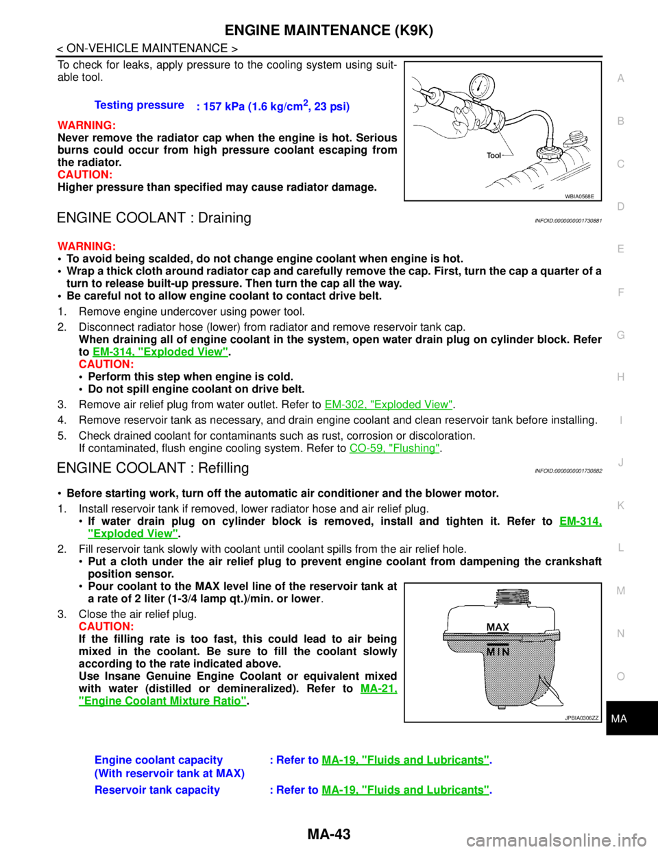
To check for leaks, apply pressure to the cooling system using suit-
able tool.
WARNING:
Never remove the radiator cap when the engine is hot. Serious
burns could occur from high pressure coolant escaping from
the radiator.
CAUTION:
Higher pressure than specified may cause radiator damage.
ENGINE COOLANT : DrainingINFOID:0000000001730881
WARNING:
To avoid being scalded, do not change engine coolant when engine is hot.
Wrap a thick cloth around radiator cap and carefully remove the cap. First, turn the cap a quarter of a
turn to release built-up pressure. Then turn the cap all the way.
Be careful not to allow engine coolant to contact drive belt.
1. Remove engine undercover using power tool.
2. Disconnect radiator hose (lower) from radiator and remove reservoir tank cap.
When draining all of engine coolant in the system, open water drain plug on cylinder block. Refer
to EM-314, "
Exploded View".
CAUTION:
Perform this step when engine is cold.
Do not spill engine coolant on drive belt.
3. Remove air relief plug from water outlet. Refer to EM-302, "
Exploded View".
4. Remove reservoir tank as necessary, and drain engine coolant and clean reservoir tank before installing.
5. Check drained coolant for contaminants such as rust, corrosion or discoloration.
If contaminated, flush engine cooling system. Refer to CO-59, "
Flushing".
ENGINE COOLANT : RefillingINFOID:0000000001730882
Before starting work, turn off the automatic air conditioner and the blower motor.
1. Install reservoir tank if removed, lower radiator hose and air relief plug.
If water drain plug on cylinder block is removed, install and tighten it. Refer to EM-314,
"Exploded View".
2. Fill reservoir tank slowly with coolant until coolant spills from the air relief hole.
Put a cloth under the air relief plug to prevent engine coolant from dampening the crankshaft
position sensor.
Pour coolant to the MAX level line of the reservoir tank at
a rate of 2 liter (1-3/4 lamp qt.)/min. or lower.
3. Close the air relief plug.
CAUTION:
If the filling rate is too fast, this could lead to air being
mixed in the coolant. Be sure to fill the coolant slowly
according to the rate indicated above.
Use Insane Genuine Engine Coolant or equivalent mixed
with water (distilled or demineralized). Refer to MA-21,
"Engine Coolant Mixture Ratio". Testing pressure
: 157 kPa (1.6 kg/cm
2, 23 psi)
WBIA0568E
JPBIA0306ZZ
Engine coolant capacity
(With reservoir tank at MAX): Refer to MA-19, "Fluids and Lubricants".
Reservoir tank capacity : Refer to MA-19, "
Fluids and Lubricants".
Page 4284 of 5883
MA-44
< ON-VEHICLE MAINTENANCE >
ENGINE MAINTENANCE (K9K)
4. Start engine without closing reservoir tank cap and keep engine racing at 1,500 rpm for about 2-3 minutes.
If necessary, pour engine coolant up to MAX level.
If coolant overflows reservoir tank hole, install filler cap.
Watch engine coolant temperature gauge so as not overheat the engine.
WARNING:
Be careful not to be scaled with hot engine coolant or vacuum pump when operating.
Radiator fan blade can start at any time and cause personal injuries.
5. Turn off the engine and loosen air relief plug until coolant spills from air relief hole.
6. Close the air relief plug and run the engine at 2,000 rpm until the upper hose becomes hot and radiator
fan operates. Leave the engine running approximately 5 minutes at idle speed and check for sound of
coolant flow while running engine from idle up to 3,000 rpm.
Sound may be noticeable at heater water cock.
7. If sound is heard, bleed air from cooling system by repeating steps 4 to 6 until coolant level no longer
drops.
Check the radiator lower hose for any signs of leakage.
8. Turn off the engine and let it cool down.
Cool down using a fan to reduce the time.
9. After cooling period, loosen the air relief plug and check if coolant spills from the air relief hole. if not,
remove the air relief plug until the coolant spills, and then close the relief air plug. Bleed air from cooling
system by repeating steps 6 to 10 until the coolant spills immediately.
10. Check the engine coolant level when engine is cool and refill to MAX level line if the level is lower.
Clean excess coolant from engine.
11. Check that the reservoir tank cap is tightened.
ENGINE COOLANT : FlushingINFOID:0000000001730883
1. Install reservoir tank if removed.
If water drain plug on cylinder block is removed, close and tighten it. Refer to EM-314, "
Exploded
View".
2. Fill reservoir tank with water until water spills from the air relief hole, then close air relief plug. Reinstall
reservoir tank cap.
3. Run engine and warm it up to normal operating temperature.
4. Rev engine two or three times under no-load.
5. Stop engine and wait until it cools down.
6. Drain water.
7. Repeat steps 1 through 6 until clear water begins to drain from radiator.
8. Blow compressed air into cooling circuit through the reservoir tank valve hole to drain all the water.
RADIATOR
RADIATOR : Checking Radiator CapINFOID:0000000001730884
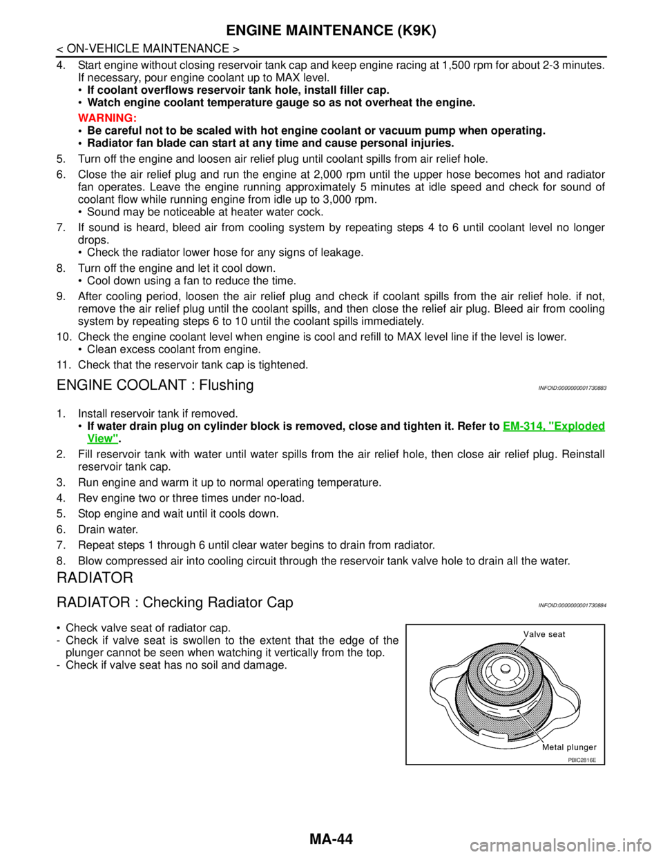
Check valve seat of radiator cap.
- Check if valve seat is swollen to the extent that the edge of the
plunger cannot be seen when watching it vertically from the top.
- Check if valve seat has no soil and damage.
PBIC2816E
Page 4287 of 5883
ENGINE MAINTENANCE (K9K)
MA-47
< ON-VEHICLE MAINTENANCE >
C
D
E
F
G
H
I
J
K
L
MB
MAN
OA
ENGINE OIL : InspectionINFOID:0000000001730878
OIL LEVEL AND MUDDINESS
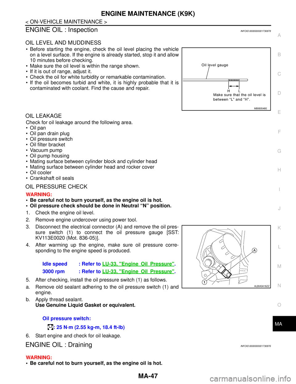
Before starting the engine, check the oil level placing the vehicle
on a level surface. If the engine is already started, stop it and allow
10 minutes before checking.
Make sure the oil level is within the range shown.
If it is out of range, adjust it.
Check the oil for white turbidity or remarkable contamination.
If the oil becomes turbid and white, it is highly probable that it is
contaminated with coolant. Find the cause and repair.
OIL LEAKAGE
Check for oil leakage around the following area.
Oil pan
Oil pan drain plug
Oil pressure switch
Oil filter bracket
Vacuum pump
Oil pump housing
Mating surface between cylinder block and cylinder head
Mating surface between cylinder head and rocker cover
Oil cooler
Crankshaft oil seals
OIL PRESSURE CHECK
WARNING:
Be careful not to burn yourself, as the engine oil is hot.
Oil pressure check should be done in Neutral “N” position.
1. Check the engine oil level.
2. Remove engine undercover using power tool.
3. Disconnect the electrical connector (A) and remove the oil pres-
sure switch (1) to connect the oil pressure gauge [SST:
KV113E0020 (Mot. 836-05)].
4. After warming up the engine, make sure oil pressure corre-
sponding to the engine speed is produced.
5. After checking, install the oil pressure switch (1) as follows.
a. Remove old sealant adhering to the oil pressure switch (1) and
engine.
b. Apply thread sealant.
Use Genuine Liquid Gasket or equivalent.
6. Start engine and check for oil leakage.
ENGINE OIL : DrainingINFOID:0000000001730876
WARNING:
Be careful not to burn yourself, as the engine oil is hot.
MBIB0548E
Idle speed : Refer to LU-33, "EngineOilPressure".
3000 rpm : Refer to LU-33, "
EngineOilPressure".
Oil pressure switch:
: 25 N·m (2.55 kg-m, 18.4 ft-lb)
ALBIA0418ZZ
Page 4314 of 5883
MWI
METER SYSTEM
MWI-7
< FUNCTION DIAGNOSIS >
C
D
E
F
G
H
I
J
K
L
MB A
O
P
METER SYSTEM : Component DescriptionINFOID:0000000001537306
SPEEDOMETER
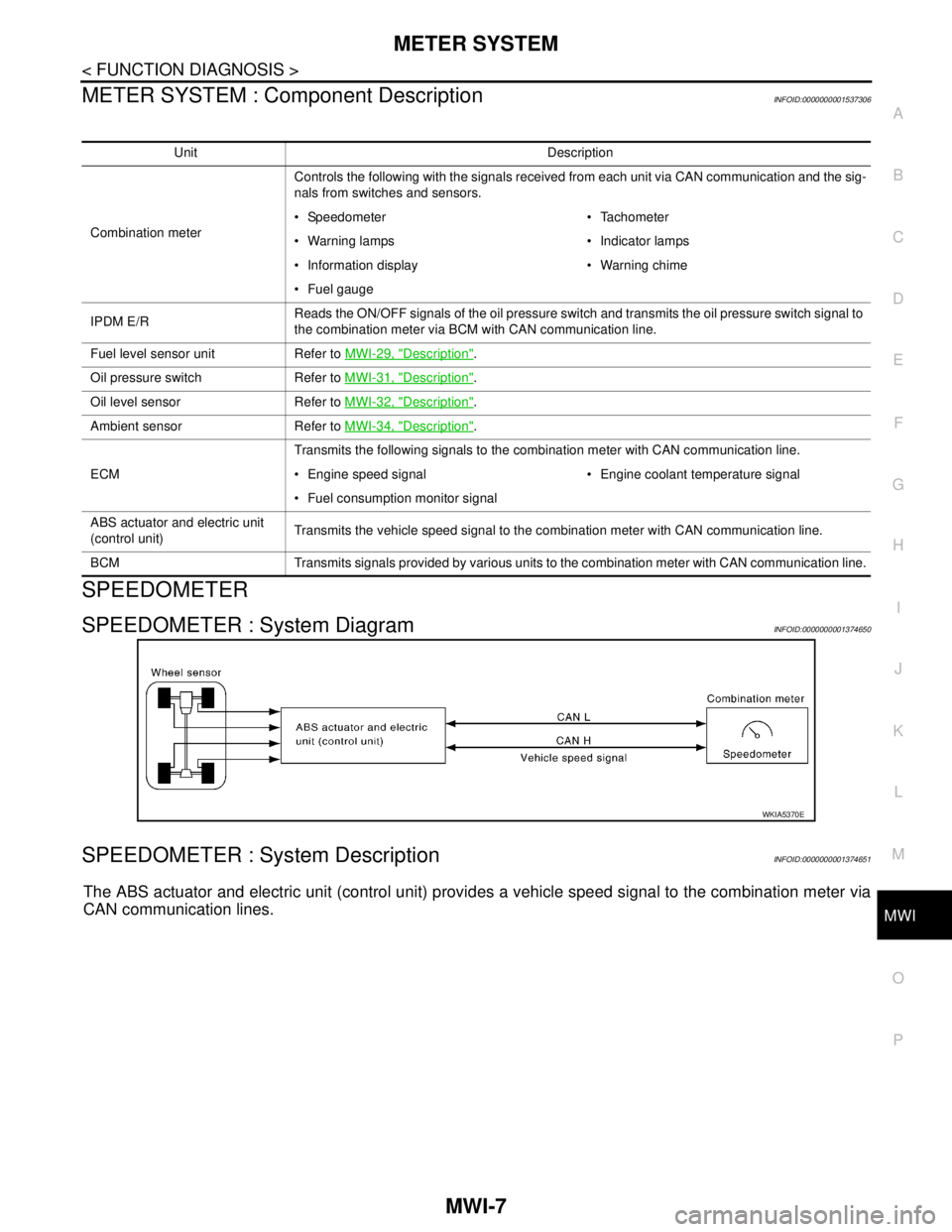
SPEEDOMETER : System DiagramINFOID:0000000001374650
SPEEDOMETER : System DescriptionINFOID:0000000001374651
The ABS actuator and electric unit (control unit) provides a vehicle speed signal to the combination meter via
CAN communication lines.
Unit Description
Combination meterControls the following with the signals received from each unit via CAN communication and the sig-
nals from switches and sensors.
Speedometer Tachometer
Warning lamps Indicator lamps
Information display Warning chime
Fuel gauge
IPDM E/RReads the ON/OFF signals of the oil pressure switch and transmits the oil pressure switch signal to
the combination meter via BCM with CAN communication line.
Fuel level sensor unit Refer to MWI-29, "
Description".
Oil pressure switch Refer to MWI-31, "
Description".
Oil level sensor Refer to MWI-32, "
Description".
Ambient sensor Refer to MWI-34, "
Description".
ECMTransmits the following signals to the combination meter with CAN communication line.
Engine speed signal Engine coolant temperature signal
Fuel consumption monitor signal
ABS actuator and electric unit
(control unit)Transmits the vehicle speed signal to the combination meter with CAN communication line.
BCM Transmits signals provided by various units to the combination meter with CAN communication line.
WKIA5370E
Page 4344 of 5883
MWI
COMBINATION METER
MWI-37
< ECU DIAGNOSIS >
C
D
E
F
G
H
I
J
K
L
MB A
O
P
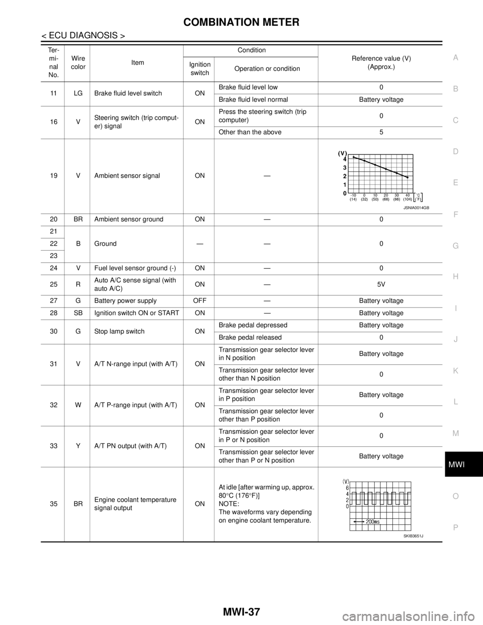
11 LG Brake fluid level switch ONBrake fluid level low 0
Brake fluid level normal Battery voltage
16 VSteering switch (trip comput-
er) signalONPress the steering switch (trip
computer)0
Other than the above 5
19 V Ambient sensor signal ON —
20 BR Ambient sensor ground ON — 0
21
BGround — — 0 22
23
24 V Fuel level sensor ground (-) ON — 0
25 RAuto A/C sense signal (with
auto A/C)ON — 5V
27 G Battery power supply OFF — Battery voltage
28 SB Ignition switch ON or START ON — Battery voltage
30 G Stop lamp switch ONBrake pedal depressed Battery voltage
Brake pedal released 0
31 V A/T N-range input (with A/T) ONTransmission gear selector lever
in N positionBattery voltage
Transmission gear selector lever
other than N position0
32 W A/T P-range input (with A/T) ONTransmission gear selector lever
in P positionBattery voltage
Transmission gear selector lever
other than P position0
33 Y A/T PN output (with A/T) ONTransmission gear selector lever
in P or N position0
Transmission gear selector lever
other than P or N positionBattery voltage
35 BREngine coolant temperature
signal outputONAt idle [after warming up, approx.
80°C (176°F)]
NOTE:
The waveforms vary depending
on engine coolant temperature. Te r -
mi-
nal
No.Wire
colorItemCondition
Reference value (V)
(Approx.) Ignition
switchOperation or condition
JSNIA0014GB
SKIB3651J
Page 4575 of 5883
PRECAUTIONS
RSU-3
< PRECAUTION >
C
D
F
G
H
I
J
K
L
MA
B
RSU
N
O
P
PRECAUTION
PRECAUTIONS
Precaution for Supplemental Restraint System (SRS) "AIR BAG" and "SEAT BELT
PRE-TENSIONER"
INFOID:0000000001724583
The Supplemental Restraint System such as “AIR BAG” and “SEAT BELT PRE-TENSIONER”, used along
with a front seat belt, helps to reduce the risk or severity of injury to the driver and front passenger for certain
types of collision. This system includes seat belt switch inputs and dual stage front air bag modules. The SRS
system uses the seat belt switches to determine the front air bag deployment, and may only deploy one front
air bag, depending on the severity of a collision and whether the front occupants are belted or unbelted.
Information necessary to service the system safely is included in the SRS and SB section of this Service Man-
ual.
WARNING:
• To avoid rendering the SRS inoperative, which could increase the risk of personal injury or death in
the event of a collision which would result in air bag inflation, all maintenance must be performed by
an authorized NISSAN/INFINITI dealer.
Improper maintenance, including incorrect removal and installation of the SRS, can lead to personal
injury caused by unintentional activation of the system. For removal of Spiral Cable and Air Bag
Module, see the SRS section.
Do not use electrical test equipment on any circuit related to the SRS unless instructed to in this
Service Manual. SRS wiring harnesses can be identified by yellow and/or orange harnesses or har-
ness connectors.
Precaution for Rear SuspensionINFOID:0000000001724584
When installing the rubber bushings, the final tightening must be done under unladen condition and with the
tires on level ground. Oil will shorten the life of the rubber bushings, so wipe off any spilled oil immediately.
Unladen condition means the fuel tank, engine coolant and lubricants are at the full specification. The spare
tire, jack, hand tools, and mats are in their designated positions.
After installing suspension components, check the wheel alignment.
Caulking nuts are not reusable. Always use new caulking nuts for installation. New caulking nuts are pre-
oiled, do not apply any additional lubrication.
Page 4577 of 5883
REAR SUSPENSION ASSEMBLY
RSU-5
< ON-VEHICLE MAINTENANCE >
C
D
F
G
H
I
J
K
L
MA
B
RSU
N
O
P
ON-VEHICLE MAINTENANCE
REAR SUSPENSION ASSEMBLY
On-Vehicle Inspection and ServiceINFOID:0000000001724575
Make sure the mounting conditions (looseness, backlash) of each component and component conditions
(wear, damage) are within specifications.
SHOCK ABSORBER INSPECTION
Check shock absorber for oil leakage, damage and replace it if necessary.
Wheel AlignmentINFOID:0000000001724576
DESCRIPTION
Measure wheel alignment under unladen conditions.
NOTE:
“Unladen conditions” means that fuel, engine coolant, and lubricant are full. Spare tire, jack, hand tools and
mats are in designated positions.
PRELIMINARY
Check the following:
1. Tires for improper air pressure and wear.
2. Road wheels for runout. Refer to WT-5, "
Inspection" .
3. Wheel bearing axial end play. Refer to RAX-5, "
On-Vehicle Inspection and Service" .
4. Shock absorber operation.
5. Each mounting part of suspension for looseness and deformation.
6. Rear suspension beam for cracks, deformation, and other damage.
7. Vehicle height (posture).
GENERAL INFORMATION AND RECOMMENDATIONS
1. A Four-Wheel Thrust Alignment should be performed.
This type of alignment is recommended for any NISSAN vehicle.
The four-wheel “thrust” process helps ensure that the vehicle is properly aligned and the steering wheel
is centered.
The alignment machine itself should be capable of accepting any NISSAN vehicle.
The alignment machine should be checked to ensure that it is level.
2. Make sure the alignment machine is properly calibrated.
Your alignment machine should be regularly calibrated in order to give correct information.
Check with the manufacturer of your specific alignment machine for their recommended Service/Cali-
bration Schedule.
THE ALIGNMENT PROCESS
IMPORTANT: Use only the alignment specifications listed in this Service Manual. Refer to RSU-5, "Wheel
Alignment" .
1. When displaying the alignment settings, many alignment machines use “indicators”: (Green/red, plus or
minus, Go/No Go). Do NOT use these indicators.
The alignment specifications programmed into your alignment machine that operate these indicators
may not be correct.
This may result in an ERROR.
2. Some newer alignment machines are equipped with an optional “Rolling Compensation” method to “com-
pensate” the sensors (alignment targets or head units). Do NOT use this “Rolling Compensation”
method.
Use the “Jacking Compensation” method. After installing the alignment targets or head units, raise the
vehicle and rotate the wheels 1/2 turn both ways.
See Instructions in the alignment machine you are using for more information.
CAMBER INSPECTION
Page 5733 of 5883

WCS-18
< FUNCTION DIAGNOSIS >
DIAGNOSIS SYSTEM (METER)
DIAGNOSIS SYSTEM (METER)
CONSULT-III Function (METER/M&A)INFOID:0000000001728303
CONSULT-III can display each diagnostic item using the diagnostic test modes shown following.
SELF-DIAG RESULTS
Display Item List
Refer to MWI-54, "DTC Index".
DATA MONITOR
Display Item List
X: Applicable
METER/M&A diagnosis mode Description
SELF-DIAG RESULTS Displays combination meter self-diagnosis results.
DATA MONITOR Displays combination meter input/output data in real time.
CAN DIAG SUPPORT MNTR The result of transmit/receive diagnosis of CAN communication can be read.
Display item [Unit]MAIN
SIGNALSSELECTION
FROM MENUDescription
SPEED METER [km/h] or [mph] X X Displays the value of vehicle speed signal.
SPEED OUTPUT [km/h] or [mph] X XDisplays the value of vehicle speed signal, which is transmitted to
each unit with CAN communication.
TACHO METER [rpm] X X Displays the value of engine speed signal, which is input from ECM.
W TEMP METER [°C] or [°F] X XDisplays the value of engine coolant temperature signal, which is in-
put from ECM.
FUEL METER [lit.] X XDisplays the value, which processes a resistance signal from fuel
gauge.
DISTANCE [km] or [mile] X XDisplays the value, which is calculated by vehicle speed signal, fuel
gauge and fuel consumption from ECM.
FUEL W/L [ON/OFF] X X Displays [ON/OFF] condition of low-fuel warning lamp.
C-ENG W/L [ON/OFF] X Displays [ON/OFF] condition of malfunction indicator lamp.
SEAT BELT W/L [ON/OFF] X Indicates [ON/OFF] condition of seat belt warning lamp.
BUZZER [ON/OFF] X X Displays [ON/OFF] condition of buzzer.
DOOR W/L [ON/OFF] X Displays [ON/OFF] condition of door warning lamp.
HI-BEAM IND [ON/OFF] X Displays [ON/OFF] condition of high beam indicator.
TURN IND [ON/OFF] X Displays [ON/OFF] condition of turn indicator.
FR FOG IND X Displays [ON/OFF] condition of front fog lamp indicator.
RR FOG IND X Displays [ON/OFF] condition of rear fog lamp indicator.
OIL W/L [ON/OFF] X Displays [ON/OFF] condition of oil pressure warning lamp.
LIGHT IND X Displays [ON/OFF] condition of exterior lamp indicator.
VDC/TCS IND [ON/OFF] X Displays [ON/OFF] condition of VDC OFF indicator lamp.
ABS W/L [ON/OFF] X Displays [ON/OFF] condition of ABS warning lamp.
SLIP IND [ON/OFF] X Displays [ON/OFF] condition of SLIP indicator lamp.
BRAKE W/L [ON/OFF] X Displays [ON/OFF] condition of brake warning lamp.*
OIL LEVEL IND X Displays [ON/OFF] condition of oil level indicator.
KEY G W/L [ON/OFF] X Displays [ON/OFF] condition of key green warning lamp.
KEY R W/L [ON/OFF] X Displays [ON/OFF] condition of key red warning lamp.
KEY KNOB W/L [ON/OFF] X Displays [ON/OFF] condition of key knob warning lamp.
PNP P SW X X Displays [ON/OFF] condition of inhibitor P switch.
Page 5753 of 5883

WCS-38
< ECU DIAGNOSIS >
COMBINATION METER
11 LG Brake fluid level switch ONBrake fluid level low 0
Brake fluid level normal Battery voltage
16 VSteering switch (trip comput-
er) signalONPress the steering switch (trip
computer)0
Other than the above 5
19 V Ambient sensor signal ON —
20 BR Ambient sensor ground ON — 0
21
BGround — — 0 22
23
24 V Fuel level sensor ground (-) ON — 0
25 RAuto A/C sense signal (with
auto A/C)ON — 5V
27 G Battery power supply OFF — Battery voltage
28 SB Ignition switch ON or START ON — Battery voltage
30 G Stop lamp switch ONBrake pedal depressed Battery voltage
Brake pedal released 0
31 V A/T N-range input (with A/T) ONTransmission gear selector lever
in N positionBattery voltage
Transmission gear selector lever
other than N position0
32 W A/T P-range input (with A/T) ONTransmission gear selector lever
in P positionBattery voltage
Transmission gear selector lever
other than P position0
33 Y A/T PN output (with A/T) ONTransmission gear selector lever
in P or N position0
Transmission gear selector lever
other than P or N positionBattery voltage
35 BREngine coolant temperature
signal outputONAt idle [after warming up, approx.
80°C (176°F)]
NOTE:
The waveforms vary depending
on engine coolant temperature. Te r -
mi-
nal
No.Wire
colorItemCondition
Reference value (V)
(Approx.) Ignition
switchOperation or condition
JSNIA0014GB
SKIB3651J