length NISSAN TIIDA 2007 Service Manual PDF
[x] Cancel search | Manufacturer: NISSAN, Model Year: 2007, Model line: TIIDA, Model: NISSAN TIIDA 2007Pages: 5883, PDF Size: 78.95 MB
Page 5210 of 5883
TM-264
< DISASSEMBLY AND ASSEMBLY >[TYPE 1 (4AT: RE4F03B)]
REPAIR FOR COMPONENT PARTS
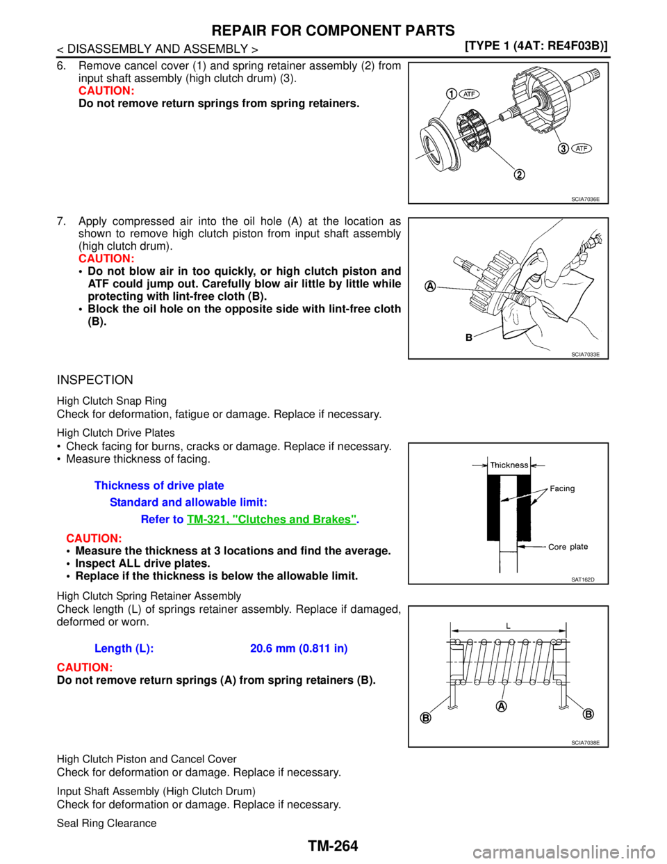
6. Remove cancel cover (1) and spring retainer assembly (2) from
input shaft assembly (high clutch drum) (3).
CAUTION:
Do not remove return springs from spring retainers.
7. Apply compressed air into the oil hole (A) at the location as
shown to remove high clutch piston from input shaft assembly
(high clutch drum).
CAUTION:
Do not blow air in too quickly, or high clutch piston and
ATF could jump out. Carefully blow air little by little while
protecting with lint-free cloth (B).
Block the oil hole on the opposite side with lint-free cloth
(B).
INSPECTION
High Clutch Snap Ring
Check for deformation, fatigue or damage. Replace if necessary.
High Clutch Drive Plates
Check facing for burns, cracks or damage. Replace if necessary.
Measure thickness of facing.
CAUTION:
Measure the thickness at 3 locations and find the average.
Inspect ALL drive plates.
Replace if the thickness is below the allowable limit.
High Clutch Spring Retainer Assembly
Check length (L) of springs retainer assembly. Replace if damaged,
deformed or worn.
CAUTION:
Do not remove return springs (A) from spring retainers (B).
High Clutch Piston and Cancel Cover
Check for deformation or damage. Replace if necessary.
Input Shaft Assembly (High Clutch Drum)
Check for deformation or damage. Replace if necessary.
Seal Ring Clearance
SCIA7036E
SCIA7033E
Thickness of drive plate
Standard and allowable limit:
Refer to TM-321, "
Clutches and Brakes".
SAT162D
Length (L): 20.6 mm (0.811 in)
SCIA7038E
Page 5216 of 5883
TM-270
< DISASSEMBLY AND ASSEMBLY >[TYPE 1 (4AT: RE4F03B)]
REPAIR FOR COMPONENT PARTS
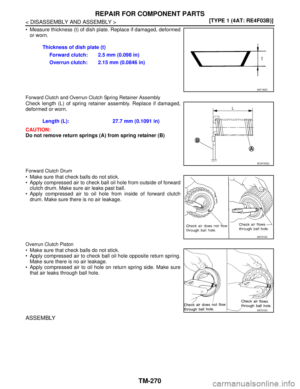
Measure thickness (t) of dish plate. Replace if damaged, deformed
or worn.
Forward Clutch and Overrun Clutch Spring Retainer Assembly
Check length (L) of spring retainer assembly. Replace if damaged,
deformed or worn.
CAUTION:
Do not remove return springs (A) from spring retainer (B)
Forward Clutch Drum
Make sure that check balls do not stick.
Apply compressed air to check ball oil hole from outside of forward
clutch drum. Make sure air leaks past ball.
Apply compressed air to oil hole from inside of forward clutch
drum. Make sure there is no air leakage.
Overrun Clutch Piston
Make sure that check balls do not stick.
Apply compressed air to check ball oil hole opposite return spring.
Make sure there is no air leakage.
Apply compressed air to oil hole on return spring side. Make sure
that air leaks through ball hole.
ASSEMBLY
Thickness of dish plate (t)
Forward clutch: 2.5 mm (0.098 in)
Overrun clutch: 2.15 mm (0.0846 in)
SAT163D
Length (L): 27.7 mm (0.1091 in)
SCIA7025J
SAT213D
SAT212D
Page 5222 of 5883
TM-276
< DISASSEMBLY AND ASSEMBLY >[TYPE 1 (4AT: RE4F03B)]
REPAIR FOR COMPONENT PARTS
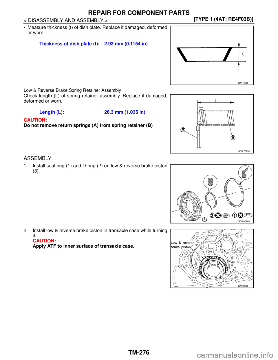
Measure thickness (t) of dish plate. Replace if damaged, deformed
or worn.
Low & Reverse Brake Spring Retainer Assembly
Check length (L) of spring retainer assembly. Replace if damaged,
deformed or worn.
CAUTION:
Do not remove return springs (A) from spring retainer (B)
ASSEMBLY
1. Install seal ring (1) and D-ring (2) on low & reverse brake piston
(3).
2. Install low & reverse brake piston in transaxle case while turning
it.
CAUTION:
Apply ATF to inner surface of transaxle case.Thickness of dish plate (t): 2.93 mm (0.1154 in)
SAT163D
Length (L): 26.3 mm (1.035 in)
SCIA7025J
SCIA6516J
SAT239D
Page 5236 of 5883
TM-290
< DISASSEMBLY AND ASSEMBLY >[TYPE 1 (4AT: RE4F03B)]
REPAIR FOR COMPONENT PARTS
INSPECTION
Pistons, Retainers and Piston Stem
Check the sliding surfaces for damage or excessive wear. Replace if necessary.
Return Springs
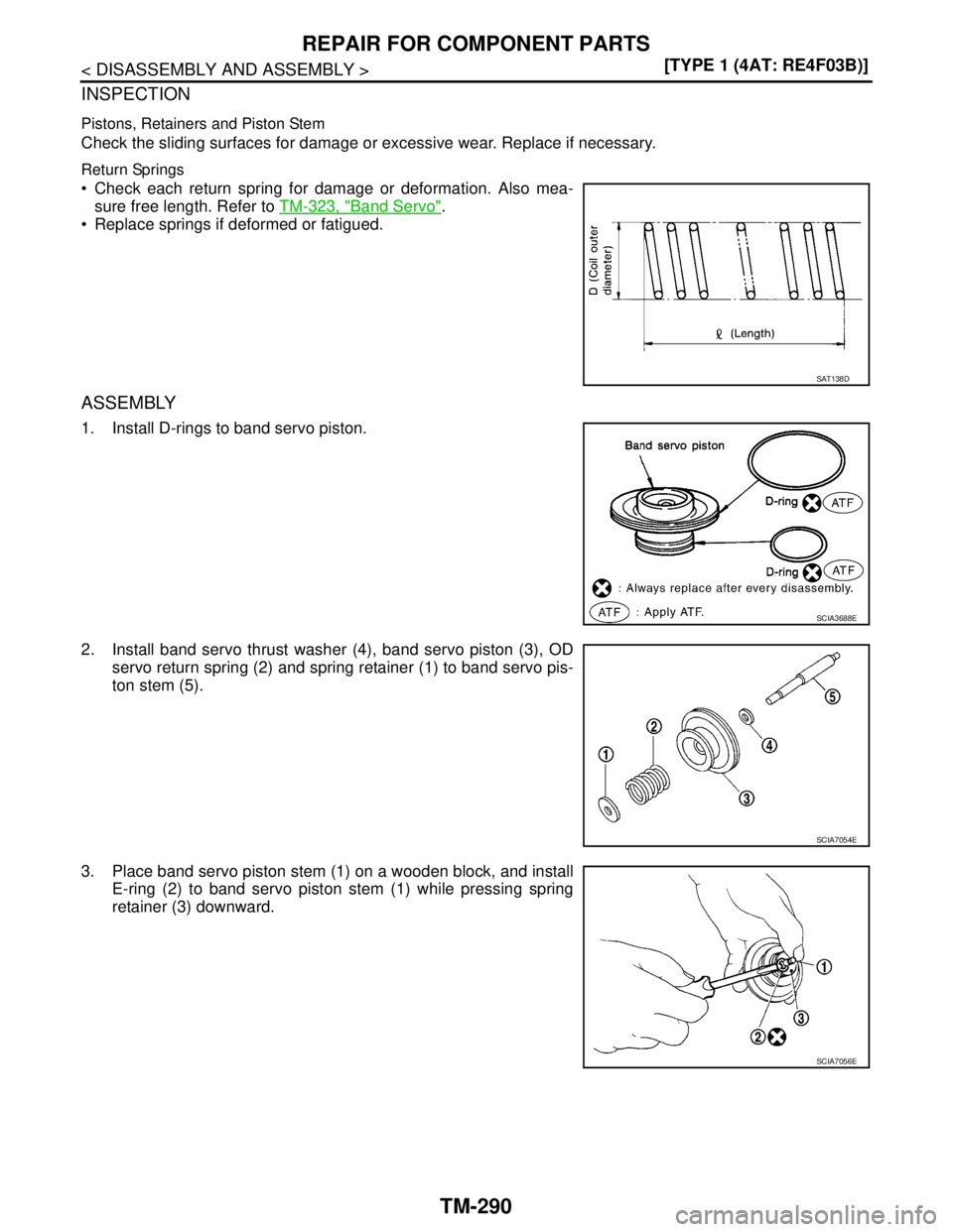
Check each return spring for damage or deformation. Also mea-
sure free length. Refer to TM-323, "
Band Servo".
Replace springs if deformed or fatigued.
ASSEMBLY
1. Install D-rings to band servo piston.
2. Install band servo thrust washer (4), band servo piston (3), OD
servo return spring (2) and spring retainer (1) to band servo pis-
ton stem (5).
3. Place band servo piston stem (1) on a wooden block, and install
E-ring (2) to band servo piston stem (1) while pressing spring
retainer (3) downward.
SAT138D
SCIA3688E
SCIA7054E
SCIA7056E
Page 5261 of 5883
ASSEMBLY
TM-315
< DISASSEMBLY AND ASSEMBLY >[TYPE 1 (4AT: RE4F03B)]
C
E
F
G
H
I
J
K
L
MA
B
TM
N
O
P
Completely remove all moisture, oil and old sealant, etc. from the transaxle case and converter
housing mating surfaces.
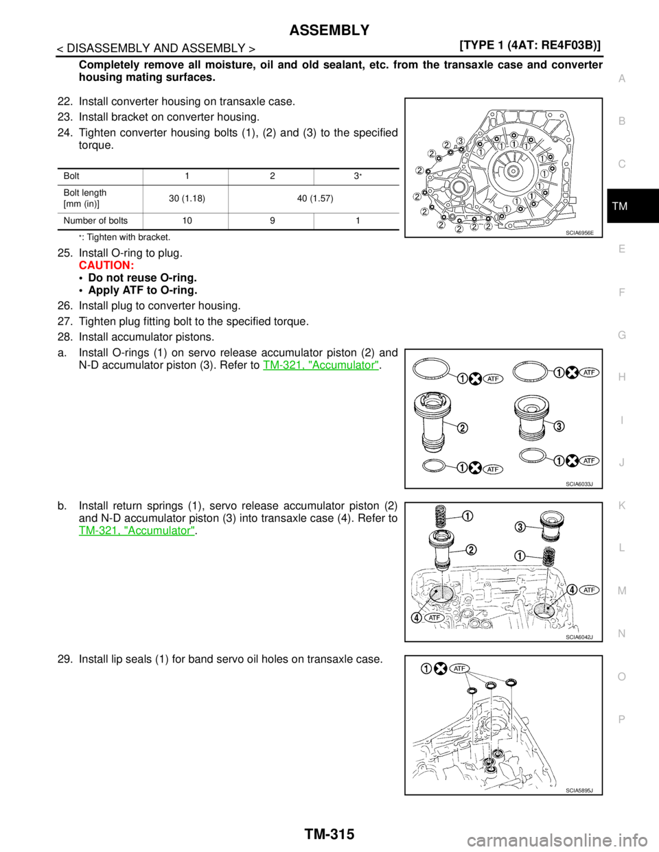
22. Install converter housing on transaxle case.
23. Install bracket on converter housing.
24. Tighten converter housing bolts (1), (2) and (3) to the specified
torque.
*: Tighten with bracket.
25. Install O-ring to plug.
CAUTION:
Do not reuse O-ring.
Apply ATF to O-ring.
26. Install plug to converter housing.
27. Tighten plug fitting bolt to the specified torque.
28. Install accumulator pistons.
a. Install O-rings (1) on servo release accumulator piston (2) and
N-D accumulator piston (3). Refer to TM-321, "
Accumulator".
b. Install return springs (1), servo release accumulator piston (2)
and N-D accumulator piston (3) into transaxle case (4). Refer to
TM-321, "
Accumulator".
29. Install lip seals (1) for band servo oil holes on transaxle case.
Bolt 1 2 3*
Bolt length
[mm (in)]30 (1.18) 40 (1.57)
Number of bolts 10 9 1
SCIA6956E
SCIA6033J
SCIA6042J
SCIA5895J
Page 5262 of 5883
TM-316
< DISASSEMBLY AND ASSEMBLY >[TYPE 1 (4AT: RE4F03B)]
ASSEMBLY
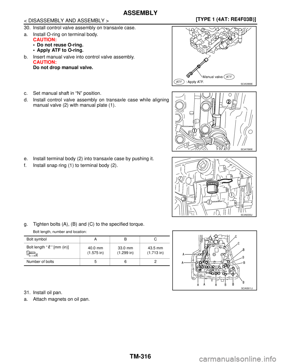
30. Install control valve assembly on transaxle case.
a. Install O-ring on terminal body.
CAUTION:
Do not reuse O-ring.
Apply ATF to O-ring.
b. Insert manual valve into control valve assembly.
CAUTION:
Do not drop manual valve.
c. Set manual shaft in “N” position.
d. Install control valve assembly on transaxle case while aligning
manual valve (2) with manual plate (1).
e. Install terminal body (2) into transaxle case by pushing it.
f. Install snap ring (1) to terminal body (2).
g. Tighten bolts (A), (B) and (C) to the specified torque.
Bolt length, number and location:
31. Install oil pan.
a. Attach magnets on oil pan.
SCIA3999E
SCIA7090E
SCIA6030J
Bolt symbol A B C
Bolt length “ ” [mm (in)]
40.0 mm
(1.575 in)33.0 mm
(1.299 in)43.5 mm
(1.713 in)
Number of bolts 5 6 2
SCIA5911J
Page 5267 of 5883
SERVICE DATA AND SPECIFICATIONS (SDS)
TM-321
< SERVICE DATA AND SPECIFICATIONS (SDS) [TYPE 1 (4AT: RE4F03B)]
C
E
F
G
H
I
J
K
L
MA
B
TM
N
O
P
Control ValvesINFOID:0000000001731393
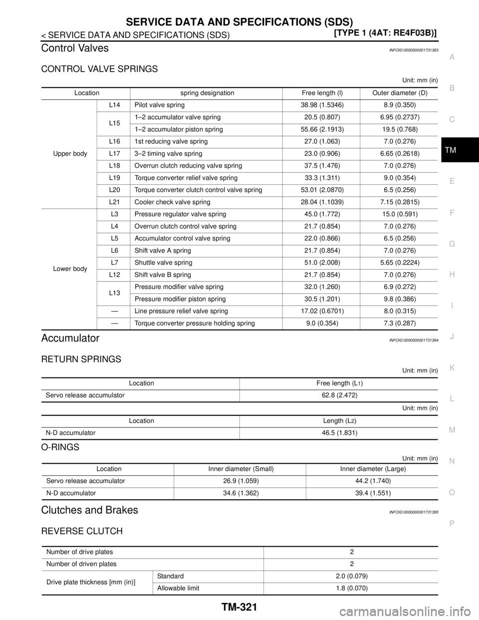
CONTROL VALVE SPRINGS
Unit: mm (in)
AccumulatorINFOID:0000000001731394
RETURN SPRINGS
Unit: mm (in)
Unit: mm (in)
O-RINGS
Unit: mm (in)
Clutches and BrakesINFOID:0000000001731395
REVERSE CLUTCH
Location spring designation Free length (l) Outer diameter (D)
Upper bodyL14 Pilot valve spring 38.98 (1.5346) 8.9 (0.350)
L151–2 accumulator valve spring 20.5 (0.807) 6.95 (0.2737)
1–2 accumulator piston spring 55.66 (2.1913) 19.5 (0.768)
L16 1st reducing valve spring 27.0 (1.063) 7.0 (0.276)
L17 3–2 timing valve spring 23.0 (0.906) 6.65 (0.2618)
L18 Overrun clutch reducing valve spring 37.5 (1.476) 7.0 (0.276)
L19 Torque converter relief valve spring 33.3 (1.311) 9.0 (0.354)
L20 Torque converter clutch control valve spring 53.01 (2.0870) 6.5 (0.256)
L21 Cooler check valve spring 28.04 (1.1039) 7.15 (0.2815)
Lower bodyL3 Pressure regulator valve spring 45.0 (1.772) 15.0 (0.591)
L4 Overrun clutch control valve spring 21.7 (0.854) 7.0 (0.276)
L5 Accumulator control valve spring 22.0 (0.866) 6.5 (0.256)
L6 Shift valve A spring 21.7 (0.854) 7.0 (0.276)
L7 Shuttle valve spring 51.0 (2.008) 5.65 (0.2224)
L12 Shift valve B spring 21.7 (0.854) 7.0 (0.276)
L13Pressure modifier valve spring 32.0 (1.260) 6.9 (0.272)
Pressure modifier piston spring 30.5 (1.201) 9.8 (0.386)
— Line pressure relief valve spring 17.02 (0.6701) 8.0 (0.315)
— Torque converter pressure holding spring 9.0 (0.354) 7.3 (0.287)
Location Free length (L1)
Servo release accumulator 62.8 (2.472)
Location Length (L2)
N-D accumulator46.5 (1.831)
Location Inner diameter (Small) Inner diameter (Large)
Servo release accumulator 26.9 (1.059) 44.2 (1.740)
N-D accumulator 34.6 (1.362) 39.4 (1.551)
Number of drive plates2
Number of driven plates2
Drive plate thickness [mm (in)]Standard 2.0 (0.079)
Allowable limit 1.8 (0.070)
Page 5269 of 5883
SERVICE DATA AND SPECIFICATIONS (SDS)
TM-323
< SERVICE DATA AND SPECIFICATIONS (SDS) [TYPE 1 (4AT: RE4F03B)]
C
E
F
G
H
I
J
K
L
MA
B
TM
N
O
P
Final DriveINFOID:0000000001731396
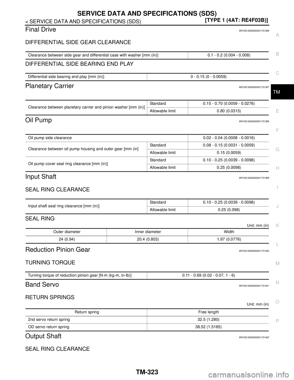
DIFFERENTIAL SIDE GEAR CLEARANCE
DIFFERENTIAL SIDE BEARING END PLAY
Planetary CarrierINFOID:0000000001731397
Oil PumpINFOID:0000000001731398
Input ShaftINFOID:0000000001731399
SEAL RING CLEARANCE
SEAL RING
Unit: mm (in)
Reduction Pinion GearINFOID:0000000001731400
TURNING TORQUE
Band ServoINFOID:0000000001731401
RETURN SPRINGS
Unit: mm (in)
Output ShaftINFOID:0000000001731402
SEAL RING CLEARANCE
Clearance between side gear and differential case with washer [mm (in)] 0.1 - 0.2 (0.004 - 0.008)
Differential side bearing end play [mm (in)] 0 - 0.15 (0 - 0.0059)
Clearance between planetary carrier and pinion washer [mm (in)]Standard 0.15 - 0.70 (0.0059 - 0.0276)
Allowable limit 0.80 (0.0315)
Oil pump side clearance0.02 - 0.04 (0.0008 - 0.0016)
Clearance between oil pump housing and outer gear [mm (in]Standard 0.08 - 0.15 (0.0031 - 0.0059)
Allowable limit 0.15 (0.0059)
Oil pump cover seal ring clearance [mm (in)]Standard 0.10 - 0.25 (0.0039 - 0.0098)
Allowable limit 0.25 (0.0098)
Input shaft seal ring clearance [mm (in)]Standard 0.10 - 0.25 (0.0039 - 0.0098)
Allowable limit 0.25 (0.098)
Outer diameter Inner diameter Width
24 (0.94) 20.4 (0.803) 1.97 (0.0776)
Turning torque of reduction pinion gear [N·m (kg-m, in-lb)] 0.11 - 0.69 (0.02 - 0.07, 1 - 6)
Return spring Free length
2nd servo return spring 32.5 (1.280)
OD servo return spring 38.52 (1.5165)
Page 5451 of 5883
TRANSAXLE ASSEMBLY
TM-505
< REMOVAL AND INSTALLATION >[TYPE 2 (4AT: RE4F03B)]
C
E
F
G
H
I
J
K
L
MA
B
TM
N
O
P
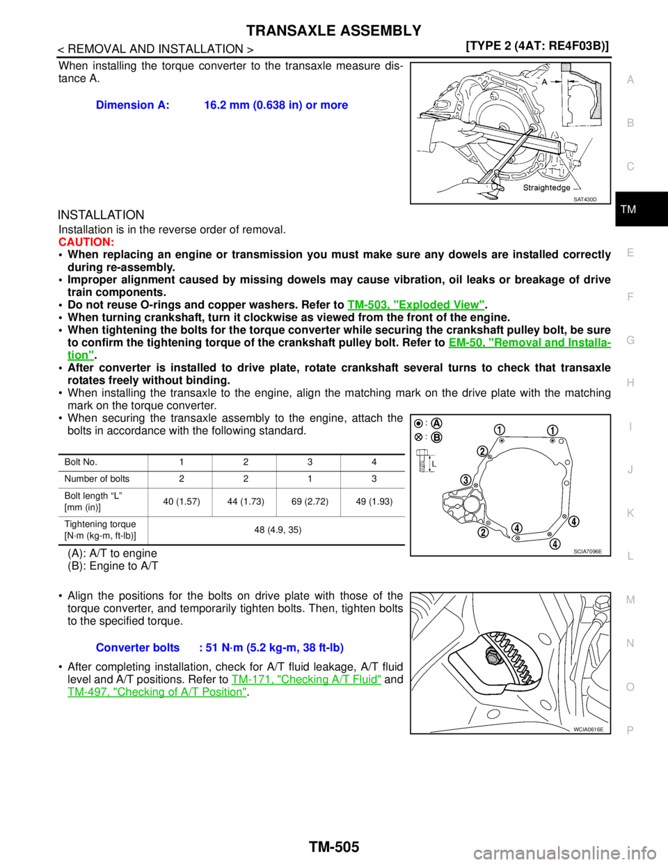
When installing the torque converter to the transaxle measure dis-
tance A.
INSTALLATION
Installation is in the reverse order of removal.
CAUTION:
When replacing an engine or transmission you must make sure any dowels are installed correctly
during re-assembly.
Improper alignment caused by missing dowels may cause vibration, oil leaks or breakage of drive
train components.
Do not reuse O-rings and copper washers. Refer to TM-503, "
Exploded View".
When turning crankshaft, turn it clockwise as viewed from the front of the engine.
When tightening the bolts for the torque converter while securing the crankshaft pulley bolt, be sure
to confirm the tightening torque of the crankshaft pulley bolt. Refer to EM-50, "
Removal and Installa-
tion".
After converter is installed to drive plate, rotate crankshaft several turns to check that transaxle
rotates freely without binding.
When installing the transaxle to the engine, align the matching mark on the drive plate with the matching
mark on the torque converter.
When securing the transaxle assembly to the engine, attach the
bolts in accordance with the following standard.
(A): A/T to engine
(B): Engine to A/T
Align the positions for the bolts on drive plate with those of the
torque converter, and temporarily tighten bolts. Then, tighten bolts
to the specified torque.
After completing installation, check for A/T fluid leakage, A/T fluid
level and A/T positions. Refer to TM-171, "
Checking A/T Fluid" and
TM-497, "
Checking of A/T Position". Dimension A: 16.2 mm (0.638 in) or more
SAT430D
Bolt No. 1234
Number of bolts 2 2 1 3
Bolt length “L”
[mm (in)]40 (1.57) 44 (1.73) 69 (2.72) 49 (1.93)
Tightening torque
[N·m (kg-m, ft-lb)]48 (4.9, 35)
SCIA7096E
Converter bolts : 51 N·m (5.2 kg-m, 38 ft-lb)
WCIA0616E
Page 5463 of 5883
DISASSEMBLY
TM-517
< DISASSEMBLY AND ASSEMBLY >[TYPE 2 (4AT: RE4F03B)]
C
E
F
G
H
I
J
K
L
MA
B
TM
N
O
P
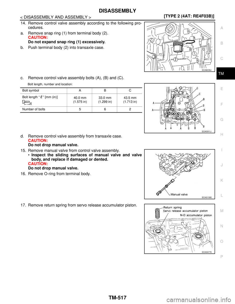
14. Remove control valve assembly according to the following pro-
cedures.
a. Remove snap ring (1) from terminal body (2).
CAUTION:
Do not expand snap ring (1) excessively.
b. Push terminal body (2) into transaxle case.
c. Remove control valve assembly bolts (A), (B) and (C).
Bolt length, number and location:
d. Remove control valve assembly from transaxle case.
CAUTION:
Do not drop manual valve.
15. Remove manual valve from control valve assembly.
Inspect the sliding surfaces of manual valve and valve
body, and replace if damaged or dented.
CAUTION:
Do not drop manual valve.
16. Remove O-ring from terminal body.
17. Remove return spring from servo release accumulator piston.
SCIA6030J
Bolt symbol A B C
Bolt length “ ” [mm (in)]
40.0 mm
(1.575 in)33.0 mm
(1.299 in)43.5 mm
(1.713 in)
Number of bolts 5 6 2
SCIA5911J
SCIA3150E
SCIA3477E