oil pressure NISSAN TIIDA 2007 Service Repair Manual
[x] Cancel search | Manufacturer: NISSAN, Model Year: 2007, Model line: TIIDA, Model: NISSAN TIIDA 2007Pages: 5883, PDF Size: 78.95 MB
Page 148 of 5883

BCS
SIGNAL BUFFER SYSTEM
BCS-13
< FUNCTION DIAGNOSIS >
C
D
E
F
G
H
I
J
K
L B A
O
P N
SIGNAL BUFFER SYSTEM
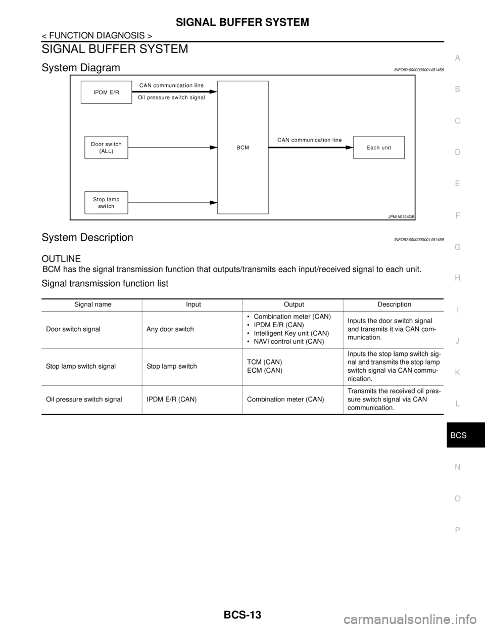
System DiagramINFOID:0000000001451458
System DescriptionINFOID:0000000001451459
OUTLINE
BCM has the signal transmission function that outputs/transmits each input/received signal to each unit.
Signal transmission function list
JPMIA0124GB
Signal name Input Output Description
Door switch signal Any door switch Combination meter (CAN)
IPDM E/R (CAN)
Intelligent Key unit (CAN)
NAVI control unit (CAN)Inputs the door switch signal
and transmits it via CAN com-
munication.
Stop lamp switch signal Stop lamp switchTCM (CAN)
ECM (CAN)Inputs the stop lamp switch sig-
nal and transmits the stop lamp
switch signal via CAN commu-
nication.
Oil pressure switch signal IPDM E/R (CAN) Combination meter (CAN)Transmits the received oil pres-
sure switch signal via CAN
communication.
Page 161 of 5883

BCS-26
< FUNCTION DIAGNOSIS >
DIAGNOSIS SYSTEM (BCM)
*: Each lamp switch is in ON position.
THEFT ALM
THEFT ALM : CONSULT-III Function (BCM - THEFT ALM)INFOID:0000000001451479
WORK SUPPORT
SIGNAL BUFFER
SIGNAL BUFFER : CONSULT-III Function (BCM - SIGNAL BUFFER)INFOID:0000000001451480
DATA MONITOR
ACTIVE TEST
PTC HEATER
PTC HEATER : CONSULT-III Function (BCM - PTC HEATER)INFOID:0000000001451481
DATA MONITOR
ACTIVE TEST
Work Item Description
SECURITY ALARM SETVehicle security function mode can be changed in this mode.
ON: Vehicle security function is ON.
OFF: Vehicle security function is OFF.
Monitor Item
[Unit]Description
OIL PRESS SW [ON/OFF] Displays the status of oil pressure switch received from IPDM E/R via CAN communication.
Test Item Operation Description
OIL PRESSURE SWOFF OFF
ONBCM transmits the oil pressure switch signal to the combination meter via CAN communica-
tion, which illuminates the oil pressure warning lamp in the combination meter.
Monitor Item
[Unit]Description
ELEC PWR CUT
[OFF/FREEZ/INHBT]Indicate [OFF/FREEZ/INHBT] condition of the PTC heater states.
FA N O N S I G
[On/Off]Displays [FAN (ON)/FAN (OFF)] status as judged from blower fan motor signal.
ENGINE STATUS
[STOP/STAL/RUN/CRA]Indicate [STOP/STALL/RUN/CRA] condition of the engine states.
ENG COOLNT T
[°C]The engine coolant temperature (determined by the signal voltage of the engine coolant tem-
perature sensor) is displayed.
BATTERY VOLT
[V]The power supply voltage of BCM is displayed.
ENGINE RPM
[rpm]Indicates the engine speed computed from the signal of the crankshaft position sensor.
OUTSIDE TEMP
[°C]The outside air temperature (determined by the signal voltage of the OAT sensor) is displayed.
Page 221 of 5883

REAR DISC BRAKE
BR-29
< ON-VEHICLE REPAIR >
C
D
E
G
H
I
J
K
L
MA
B
BR
N
O
P
3. Drain brake fluid. Refer to BR-8, "Bleeding Brake System".
4. Remove connecting bolt and torque member bolts using power tool, and remove cylinder body.
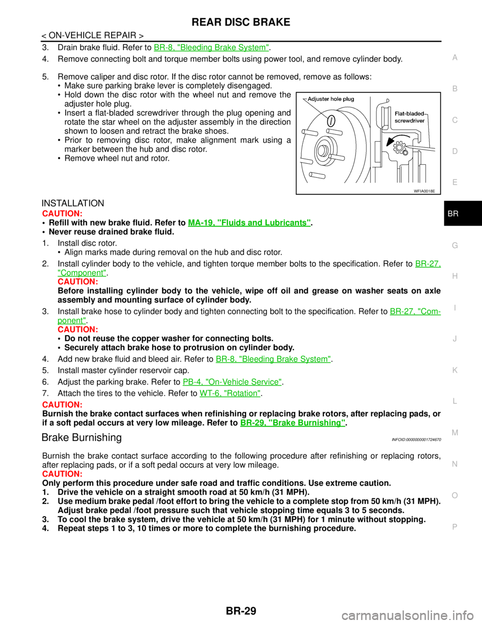
5. Remove caliper and disc rotor. If the disc rotor cannot be removed, remove as follows:
Make sure parking brake lever is completely disengaged.
Hold down the disc rotor with the wheel nut and remove the
adjuster hole plug.
Insert a flat-bladed screwdriver through the plug opening and
rotate the star wheel on the adjuster assembly in the direction
shown to loosen and retract the brake shoes.
Prior to removing disc rotor, make alignment mark using a
marker between the hub and disc rotor.
Remove wheel nut and rotor.
INSTALLATION
CAUTION:
Refill with new brake fluid. Refer to MA-19, "
Fluids and Lubricants".
Never reuse drained brake fluid.
1. Install disc rotor.
Align marks made during removal on the hub and disc rotor.
2. Install cylinder body to the vehicle, and tighten torque member bolts to the specification. Refer to BR-27,
"Component".
CAUTION:
Before installing cylinder body to the vehicle, wipe off oil and grease on washer seats on axle
assembly and mounting surface of cylinder body.
3. Install brake hose to cylinder body and tighten connecting bolt to the specification. Refer to BR-27, "
Com-
ponent".
CAUTION:
Do not reuse the copper washer for connecting bolts.
Securely attach brake hose to protrusion on cylinder body.
4. Add new brake fluid and bleed air. Refer to BR-8, "
Bleeding Brake System".
5. Install master cylinder reservoir cap.
6. Adjust the parking brake. Refer to PB-4, "
On-Vehicle Service".
7. Attach the tires to the vehicle. Refer to WT-6, "
Rotation".
CAUTION:
Burnish the brake contact surfaces when refinishing or replacing brake rotors, after replacing pads, or
if a soft pedal occurs at very low mileage. Refer to BR-29, "
Brake Burnishing".
Brake BurnishingINFOID:0000000001724670
Burnish the brake contact surface according to the following procedure after refinishing or replacing rotors,
after replacing pads, or if a soft pedal occurs at very low mileage.
CAUTION:
Only perform this procedure under safe road and traffic conditions. Use extreme caution.
1. Drive the vehicle on a straight smooth road at 50 km/h (31 MPH).
2. Use medium brake pedal /foot effort to bring the vehicle to a complete stop from 50 km/h (31 MPH).
Adjust brake pedal /foot pressure such that vehicle stopping time equals 3 to 5 seconds.
3. To cool the brake system, drive the vehicle at 50 km/h (31 MPH) for 1 minute without stopping.
4. Repeat steps 1 to 3, 10 times or more to complete the burnishing procedure.
WFIA0018E
Page 437 of 5883
![NISSAN TIIDA 2007 Service Repair Manual CHG-16
< SERVICE DATA AND SPECIFICATIONS (SDS) [HR16DE]
SERVICE DATA AND SPECIFICATIONS (SDS)
SERVICE DATA AND SPECIFICATIONS (SDS)
SERVICE DATA AND SPECIFICATIONS (SDS)
GeneratorINFOID:00000000016894 NISSAN TIIDA 2007 Service Repair Manual CHG-16
< SERVICE DATA AND SPECIFICATIONS (SDS) [HR16DE]
SERVICE DATA AND SPECIFICATIONS (SDS)
SERVICE DATA AND SPECIFICATIONS (SDS)
SERVICE DATA AND SPECIFICATIONS (SDS)
GeneratorINFOID:00000000016894](/img/5/57395/w960_57395-436.png)
CHG-16
< SERVICE DATA AND SPECIFICATIONS (SDS) [HR16DE]
SERVICE DATA AND SPECIFICATIONS (SDS)
SERVICE DATA AND SPECIFICATIONS (SDS)
SERVICE DATA AND SPECIFICATIONS (SDS)
GeneratorINFOID:0000000001689489
Applied modelHR16DE
Ty p eA2TJ0291ZE
MITSUBISHI
Nominal rating [V - A] 12 - 120
Ground polarityNegative
Minimum revolution under no-load (When 13.5
V is applied)[rpm] Less than 1,300
Hot output current (When 13.5 V is applied) [A/rpm]More than 27/1,300
More than 95/2,500
More than 116/5,000
Regulated output voltage [V] 14.1 - 14.7
Minimum length of brush [mm (in)] More than 5.00 (0.197)
Brush spring pressure [N (g, oz)] 4.1 - 5.3 (418 - 541, 14.7 - 19.1)
Slip ring minimum outer diameter [mm (in)] More than 22.1 (0.870)
Rotor (Field coil) resistance [Ω] 1.7 - 2.2
Page 451 of 5883
![NISSAN TIIDA 2007 Service Repair Manual CHG-30
< SERVICE DATA AND SPECIFICATIONS (SDS) [MR18DE]
SERVICE DATA AND SPECIFICATIONS (SDS)
SERVICE DATA AND SPECIFICATIONS (SDS)
SERVICE DATA AND SPECIFICATIONS (SDS)
GeneratorINFOID:00000000016907 NISSAN TIIDA 2007 Service Repair Manual CHG-30
< SERVICE DATA AND SPECIFICATIONS (SDS) [MR18DE]
SERVICE DATA AND SPECIFICATIONS (SDS)
SERVICE DATA AND SPECIFICATIONS (SDS)
SERVICE DATA AND SPECIFICATIONS (SDS)
GeneratorINFOID:00000000016907](/img/5/57395/w960_57395-450.png)
CHG-30
< SERVICE DATA AND SPECIFICATIONS (SDS) [MR18DE]
SERVICE DATA AND SPECIFICATIONS (SDS)
SERVICE DATA AND SPECIFICATIONS (SDS)
SERVICE DATA AND SPECIFICATIONS (SDS)
GeneratorINFOID:0000000001690788
Ty p eH90-128SC
MITSUBISHI make
Nominal rating12 V - 90 A
Ground polarityNegative
Minimum revolution under no-load (when 13.5 V is applied) Less than 1,200 rpm
Hot output current (when 13.5 V is applied)More than 27 A/1,300 rpm
More than 76 A/2,500 rpm
More than 85 A/5,000 rpm
Regulated output voltage14.1 - 14.7 V
Minimum length of brush More than 6.00 mm (0.236 in)
Brush spring pressure 1.1 - 3.7 N (112 - 378 g, 4.00 - 13.3 oz)
Slip ring minimum outer diameter More than 14.7 mm (0.579 in)
Rotor (field coil) resistance 1.61 - 1.91 Ω
Page 465 of 5883
![NISSAN TIIDA 2007 Service Repair Manual CHG-44
< SERVICE DATA AND SPECIFICATIONS (SDS) [K9K]
SERVICE DATA AND SPECIFICATIONS (SDS)
SERVICE DATA AND SPECIFICATIONS (SDS)
SERVICE DATA AND SPECIFICATIONS (SDS)
GeneratorINFOID:0000000001691231
NISSAN TIIDA 2007 Service Repair Manual CHG-44
< SERVICE DATA AND SPECIFICATIONS (SDS) [K9K]
SERVICE DATA AND SPECIFICATIONS (SDS)
SERVICE DATA AND SPECIFICATIONS (SDS)
SERVICE DATA AND SPECIFICATIONS (SDS)
GeneratorINFOID:0000000001691231](/img/5/57395/w960_57395-464.png)
CHG-44
< SERVICE DATA AND SPECIFICATIONS (SDS) [K9K]
SERVICE DATA AND SPECIFICATIONS (SDS)
SERVICE DATA AND SPECIFICATIONS (SDS)
SERVICE DATA AND SPECIFICATIONS (SDS)
GeneratorINFOID:0000000001691231
Applied modelK9K
Ty p e0 124 525 082
BOSCH make
Nominal rating [V - A] —
Ground polarity—
Minimum revolution under no-load (When 13.5 V
is applied)[rpm] —
Hot output current (When 13.5 V is applied) [A/rpm] —
Regulated output voltage [V] —
Minimum length of brush [mm (in)] —
Brush spring pressure [N (g, oz)] —
Slip ring minimum outer diameter [mm (in)] —
Rotor (Field coil) resistance [Ω]—
Page 469 of 5883

CL-4
< SERVICE INFORMATION >
NOISE, VIBRATION AND HARSHNESS (NVH) TROUBLESHOOTING
NOISE, VIBRATION AND HARSHNESS (NVH) TROUBLESHOOTING
NVH Troubleshooting ChartINFOID:0000000001375292
Use the chart below to help you find the cause of the symptom. The numbers indicate the order of the inspec-
tion. If necessary, repair or replace these parts.
Reference pageCL-5CL-8EM-207EM-302CL-11CL-13
XX-XX, "*****"
SUSPECTED PARTS (Possible cause)
CLUTCH PEDAL (Inspection and adjustment)
CLUTCH LINE (Air in line)
ENGINE MOUNTING (Loose)
CSC (Concentric slave cylinder) (Worn, dirty or damaged)
CLUTCH DISC (Out of true)
CLUTCH DISC (Runout is excessive)
CLUTCH DISC (Lining broken)
CLUTCH DISC (Dirty or burned)
CLUTCH DISC (Oily)
CLUTCH DISC (Worn out)
CLUTCH DISC (Hardened)
CLUTCH DISC (Lack of spline grease)
DIAPHRAGM SPRING (Damaged)
DIAPHRAGM SPRING (Out of tip alignment)
PRESSURE PLATE (Distortion)
FLYWHEEL (Distortion)
SymptomClutch grabs/chatters 1 2 2 2 2 2
Clutch pedal spongy 1
Clutch noisy 1
Clutch slips 1 2 2 3 4 5
Clutch does not disengage 12 55555 5667
Page 478 of 5883

CLUTCH DISC, CLUTCH COVER AND FLYWHEEL
CL-13
< SERVICE INFORMATION >
C
E
F
G
H
I
J
K
L
MA
B
CL
N
O
P
CLUTCH DISC, CLUTCH COVER AND FLYWHEEL
Removal and InstallationINFOID:0000000001375299
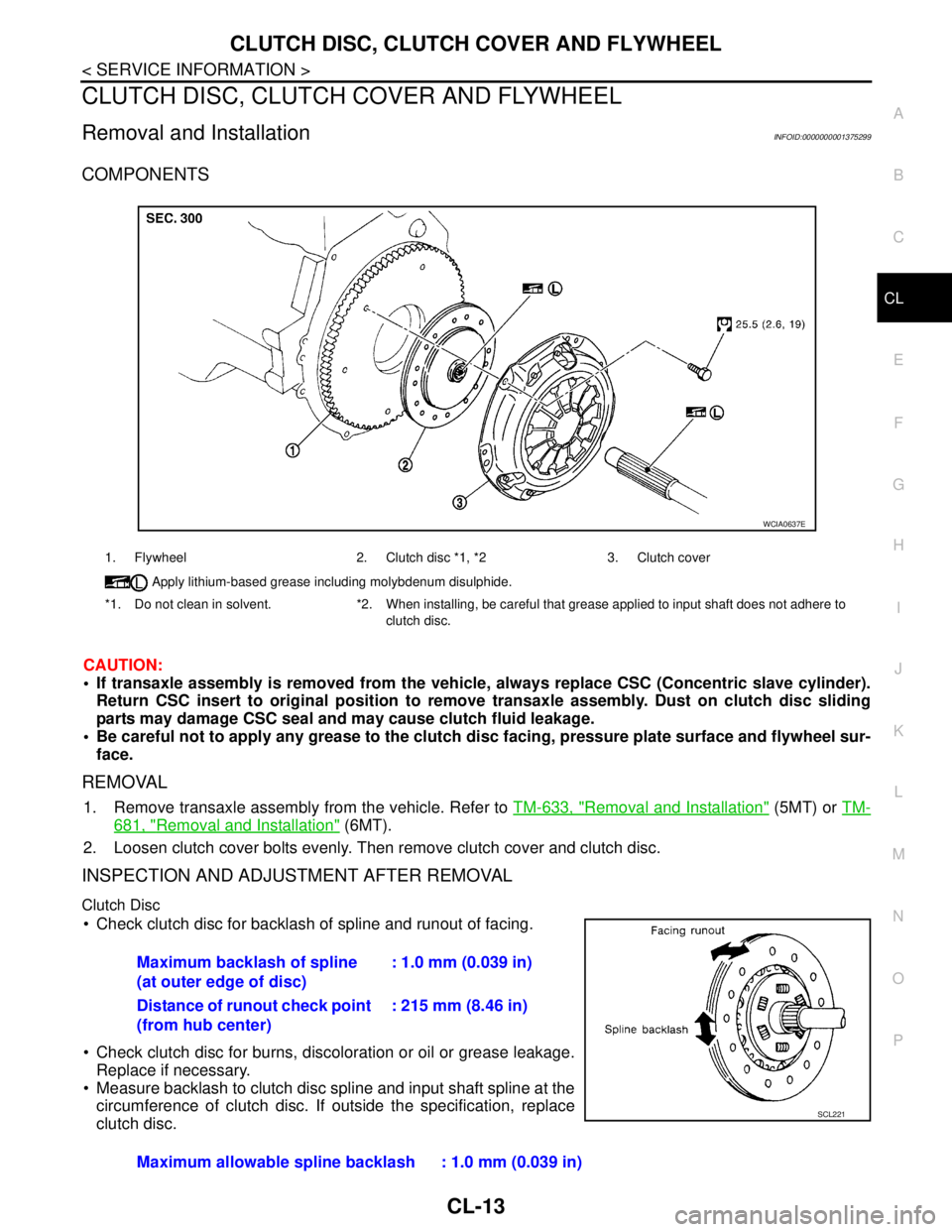
COMPONENTS
CAUTION:
If transaxle assembly is removed from the vehicle, always replace CSC (Concentric slave cylinder).
Return CSC insert to original position to remove transaxle assembly. Dust on clutch disc sliding
parts may damage CSC seal and may cause clutch fluid leakage.
Be careful not to apply any grease to the clutch disc facing, pressure plate surface and flywheel sur-
face.
REMOVAL
1. Remove transaxle assembly from the vehicle. Refer to TM-633, "Removal and Installation" (5MT) or TM-
681, "Removal and Installation" (6MT).
2. Loosen clutch cover bolts evenly. Then remove clutch cover and clutch disc.
INSPECTION AND ADJUSTMENT AFTER REMOVAL
Clutch Disc
Check clutch disc for backlash of spline and runout of facing.
Check clutch disc for burns, discoloration or oil or grease leakage.
Replace if necessary.
Measure backlash to clutch disc spline and input shaft spline at the
circumference of clutch disc. If outside the specification, replace
clutch disc.
1. Flywheel 2. Clutch disc *1, *2 3. Clutch cover
Apply lithium-based grease including molybdenum disulphide.
*1. Do not clean in solvent. *2. When installing, be careful that grease applied to input shaft does not adhere to
clutch disc.
WCIA0637E
Maximum backlash of spline
(at outer edge of disc): 1.0 mm (0.039 in)
Distance of runout check point
(from hub center): 215 mm (8.46 in)
Maximum allowable spline backlash : 1.0 mm (0.039 in)
SCL221
Page 495 of 5883
![NISSAN TIIDA 2007 Service Repair Manual CO-14
< ON-VEHICLE MAINTENANCE >[HR16DE]
RADIATOR
RADIATOR
Checking Radiator CapINFOID:0000000001534602
Check valve seat of radiator cap.
- Check if valve seat is swollen to the extent that the edg NISSAN TIIDA 2007 Service Repair Manual CO-14
< ON-VEHICLE MAINTENANCE >[HR16DE]
RADIATOR
RADIATOR
Checking Radiator CapINFOID:0000000001534602
Check valve seat of radiator cap.
- Check if valve seat is swollen to the extent that the edg](/img/5/57395/w960_57395-494.png)
CO-14
< ON-VEHICLE MAINTENANCE >[HR16DE]
RADIATOR
RADIATOR
Checking Radiator CapINFOID:0000000001534602
Check valve seat of radiator cap.
- Check if valve seat is swollen to the extent that the edge of the
plunger cannot be seen when watching it vertically from the top.
- Check if valve seat has no soil and damage.
Pull negative-pressure valve to open it, and make sure that it is
completely closed when released.
- Make sure that there is no dirt or damage on the valve seat of radi-
ator cap negative-pressure valve.
- Make sure that the valve operates properly in the opening and
closing conditions.
Check radiator cap relief pressure using suitable tool.
- When connecting the radiator cap to the tester, apply water or
coolant to the cap seal surface.
- Replace the radiator cap if there is an abnormality in the negative-
pressure valve, or if the open-valve pressure is outside of the stan-
dard values.
Replace radiator cap if there it does not comply to specifications to the above three checks.
CAUTION:
When installing radiator cap, thoroughly wipe out the radiator filler neck to remove any waxy residue
or foreign material.
Checking RadiatorINFOID:0000000001534603
Check radiator for mud or clogging. If necessary, clean radiator as follows.
Be careful not to bend or damage radiator fins.
When radiator is cleaned without removal, remove all surrounding parts such as cooling fan, radiator shroud
and horns. Then tape harness and connectors to prevent water from entering.
1. Apply water by hose to the back side of the radiator core vertically downward.
2. Apply water again to all radiator core surface once per minute.
3. Stop washing if any stains no longer flow out from radiator.
4. Blow air into the back side of radiator core vertically downward.
Use compressed air lower than 490 kPa (4.9 bar, 5 kg/cm
2, 71 psi) and keep distance more than 30 cm
(11.8 in).
PBIC2816E
SMA967B
Standard: 78 – 98 kPa (0.78 - 0.98 bar, 0.8 – 1.0 kg/cm2, 11
– 14 psi)
Limit: 59 kPa (0.59 bar, 0.6 kg/cm
2, 9 psi)
WBIA0570E
Page 519 of 5883
![NISSAN TIIDA 2007 Service Repair Manual CO-38
< ON-VEHICLE MAINTENANCE >[MR18DE]
RADIATOR
RADIATOR
Checking Radiator CapINFOID:0000000001337842
Check valve seat of radiator cap.
- Check if valve seat is swollen to the extent that the edg NISSAN TIIDA 2007 Service Repair Manual CO-38
< ON-VEHICLE MAINTENANCE >[MR18DE]
RADIATOR
RADIATOR
Checking Radiator CapINFOID:0000000001337842
Check valve seat of radiator cap.
- Check if valve seat is swollen to the extent that the edg](/img/5/57395/w960_57395-518.png)
CO-38
< ON-VEHICLE MAINTENANCE >[MR18DE]
RADIATOR
RADIATOR
Checking Radiator CapINFOID:0000000001337842
Check valve seat of radiator cap.
- Check if valve seat is swollen to the extent that the edge of the
plunger cannot be seen when watching it vertically from the top.
- Check if valve seat has no soil and damage.
Pull negative-pressure valve to open it, and make sure that it is
completely closed when released.
- Make sure that there is no dirt or damage on the valve seat of radi-
ator cap negative-pressure valve.
- Make sure that the valve operates properly in the opening and
closing conditions.
Check radiator cap relief pressure using suitable tool.
- When connecting the radiator cap to the tester, apply water or
coolant to the cap seal surface.
- Replace the radiator cap if there is an abnormality in the negative-
pressure valve, or if the open-valve pressure is outside of the stan-
dard values.
Replace radiator cap if there it does not comply to specifications to the above three checks.
CAUTION:
When installing radiator cap, thoroughly wipe out the radiator filler neck to remove any waxy residue
or foreign material.
Checking RadiatorINFOID:0000000001337843
Check radiator for mud or clogging. If necessary, clean radiator as follows.
Be careful not to bend or damage radiator fins.
When radiator is cleaned without removal, remove all surrounding parts such as cooling fan, radiator shroud
and horns. Then tape harness and connectors to prevent water from entering.
1. Apply water by hose to the back side of the radiator core vertically downward.
2. Apply water again to all radiator core surface once per minute.
3. Stop washing if any stains no longer flow out from radiator.
4. Blow air into the back side of radiator core vertically downward.
Use compressed air lower than 490 kPa (4.9 bar, 5 kg/cm
2, 71 psi) and keep distance more than 30 cm
(11.8 in).
PBIC2816E
SMA967B
Standard: 78 – 98 kPa (0.78 - 0.98 bar, 0.8 – 1.0 kg/cm2, 11
– 14 psi)
Limit: 59 kPa (0.59 bar, 0.6 kg/cm
2, 9 psi)
WBIA0570E