battery replacement NISSAN TIIDA 2007 Service Repair Manual
[x] Cancel search | Manufacturer: NISSAN, Model Year: 2007, Model line: TIIDA, Model: NISSAN TIIDA 2007Pages: 5883, PDF Size: 78.95 MB
Page 12 of 5883
![NISSAN TIIDA 2007 Service Repair Manual AV
AUDIO SYSTEM
AV-7
< FUNCTION DIAGNOSIS >[AUDIO WITHOUT NAVIGATION]
C
D
E
F
G
H
I
J
K
L
MB A
O
P Description
The link with the NATS IMMU implies that the AV control unit can basically only be operat NISSAN TIIDA 2007 Service Repair Manual AV
AUDIO SYSTEM
AV-7
< FUNCTION DIAGNOSIS >[AUDIO WITHOUT NAVIGATION]
C
D
E
F
G
H
I
J
K
L
MB A
O
P Description
The link with the NATS IMMU implies that the AV control unit can basically only be operat](/img/5/57395/w960_57395-11.png)
AV
AUDIO SYSTEM
AV-7
< FUNCTION DIAGNOSIS >[AUDIO WITHOUT NAVIGATION]
C
D
E
F
G
H
I
J
K
L
MB A
O
P Description
The link with the NATS IMMU implies that the AV control unit can basically only be operated if connected to the
matching NATS IMMU to which the AV control unit was initially fitted on the production line.
Since radio operation is impossible after the link with the NATS is disrupted, theft of the AV control unit is basi-
cally useless since special equipment is required to reset the AV control unit.
Initialization Process for AV control units That Are Linked to the NATS IMMU
New AV control units will be delivered to the factories in the “NEW” state, i.e. ready to be linked with the vehi-
cle's NATS. When the AV control unit in “NEW” state is first switched on at the factory, it will start up communi-
cation with the vehicle's immobilizer control unit (IMMU) and send a code (the “AV control unit Code”) to the
IMMU. The IMMU will then store this code, which is unique to each AV control unit, in its (permanent) memory.
Upon receipt of the code by the IMMU, the NATS will confirm correct receipt of the AV control unit code to the
AV control unit. Hereafter, the AV control unit will operate as normal.
During the initialization process, “NEW” is displayed on the AV control unit display. Normally though, communi-
cation between AV control unit and IMMU takes such a short time (300 ms) that the AV control unit seems to
switch on directly without showing “NEW” on its display.
Normal Operation
Each time the AV control unit is switched on afterwards, the AV control unit code will be verified between the
AV control unit and the NATS before the AV control unit becomes operational. During the code verification pro-
cess, “WAIT” is shown on the AV control unit display. Again, the communication takes such a short time (300
ms) that the AV control unit seems to switch on directly without showing “WAIT” on its display.
When The Radio Is Locked
In case of the AV control unit being linked with the vehicle's NATS (immobilizer system), disconnection of the
link between the AV control unit and the IMMU will cause the AV control unit to switch into the lock
(“SECURE”) mode in which the AV control unit is fully inoperative. Hence, repair of the AV control unit is basi-
cally impossible, unless the AV control unit is reset to the “NEW” state for which special decoding equipment is
required.
Clarion has provided their authorized service representatives with so called “decoder boxes” which can bring
the AV control unit back to the “NEW” state, enabling the AV control unit to be switched on after which repair
can be performed. Subsequently, when the repaired AV control unit is delivered to the final user again, it will
be in the “NEW” state to enable re-linking the AV control unit to the vehicle's immobilizer system. As a result of
the above, repair of the AV control unit can only be done by an authorized Clarion representative (when the
owner of the vehicle requests repair and can show personal identification).
Service Procedure
Item Service procedure Description
Battery disconnection No additional action required. –
Radio needs repair Repair needs to be done by authorized rep-
resentative of radio manufacturer since ra-
dio cannot be operated unless it is reset to
NEW state, using special decoding equip-
ment.–
Replacement of radio by new part No additional action required. Radio is delivered in “NEW” state.
Transferring radio to another vehicle/re-
placement of radio by an old partRadio needs to be reset to NEW state by
authorized representative of radio manu-
facturer.–
Replacement of IMMU Radio needs to be reset to NEW state by
authorized representative of Clarion.After switching on the radio, it will display
“SECURE” after 1 minute.
No communication from IMMU to radio 1. Check NATS system if NATS is mal-
functioning.
2. Reset radio to “NEW” state by autho-
rized representative of Clarion after
NATS is repaired.The radio will display “SECURE” after 1
minute after switching on the radio. Further
use of radio is impossible until communica-
tion is established again, or after radio is re-
set by authorized representative of Clarion.
When initialized between ECM and IMMU. Radio needs to be reset to “NEW” status by
authorized representative of Clarion.It will display “SECURE” after 1 minute after
switching on the radio.
Page 2655 of 5883
![NISSAN TIIDA 2007 Service Repair Manual EM-8
< PRECAUTION >[HR16DE]
PRECAUTIONS
3. Disconnect both battery cables. The steering lock will remain released and the steering wheel can be
rotated.
4. Perform the necessary repair operation.
5. W NISSAN TIIDA 2007 Service Repair Manual EM-8
< PRECAUTION >[HR16DE]
PRECAUTIONS
3. Disconnect both battery cables. The steering lock will remain released and the steering wheel can be
rotated.
4. Perform the necessary repair operation.
5. W](/img/5/57395/w960_57395-2654.png)
EM-8
< PRECAUTION >[HR16DE]
PRECAUTIONS
3. Disconnect both battery cables. The steering lock will remain released and the steering wheel can be
rotated.
4. Perform the necessary repair operation.
5. When the repair work is completed, return the ignition switch to the ″LOCK″ position before connecting
the battery cables. (At this time, the steering lock mechanism will engage.)
6. Perform a self-diagnosis check of all control units using CONSULT-II.
Precaution for Drain CoolantINFOID:0000000001527635
Drain coolant when engine is cooled.
Precaution for Disconnecting Fuel PipingINFOID:0000000001527636
Before starting work, make sure no fire or spark producing items are in the work area.
Release fuel pressure before disassembly.
After disconnecting pipes, plug openings to stop fuel leakage.
Precaution for Removal and DisassemblyINFOID:0000000001527637
When instructed to use special service tools, use the specified tools. Always be careful to work safely, avoid
forceful or uninstructed operations.
Exercise maximum care to avoid damage to mating or sliding surfaces.
Cover openings of engine system with tape or the equivalent, if necessary, to seal out foreign materials.
Mark and arrange disassembly parts in an organized way for easy troubleshooting and assembly.
When loosening nuts and bolts, as a basic rule, start with the one furthest outside, then the one diagonally
opposite, and so on. If the order of loosening is specified, do exactly as specified. Power tools may be used
where noted in the step.
Precaution for Inspection, Repair and ReplacementINFOID:0000000001527638
Before repairing or replacing, thoroughly inspect parts. Inspect new replacement parts in the same way, and
replace if necessary.
Precaution for Assembly and InstallationINFOID:0000000001527639
Use torque wrench to tighten bolts or nuts to specification.
When tightening nuts and bolts, as a basic rule, equally tighten in several different steps starting with the
ones in center, then ones on inside and outside diagonally in this order. If the order of tightening is specified,
do exactly as specified.
Replace with new gasket, packing, oil seal or O-ring.
Thoroughly wash, clean, and air-blow each part. Carefully check oil or coolant passages for any restriction
and blockage.
Avoid damaging sliding or mating surfaces. Completely remove foreign materials such as cloth lint or dust.
Before assembly, oil sliding surfaces well.
Release air within route after draining coolant.
Before starting engine, apply fuel pressure to fuel lines with turning ignition switch ON (with engine stopped).
Then make sure that there are no leaks at fuel line connections.
After repairing, start engine and increase engine speed to check coolant, fuel, oil, and exhaust systems for
leakage.
Parts Requiring Angular TighteningINFOID:0000000001527640
Use an angle wrench for the final tightening of the following engine parts:
- Cylinder head bolts
- Camshaft sprocket (INT)
- Main bearing cap bolts
- Connecting rod cap nuts
- Crankshaft pulley bolt (No angle wrench is required as the bolt flange is provided with notches for angular
tightening)
Do not use a torque value for final tightening. Tool number : KV10112100 (BT-8653-A)
Page 2782 of 5883
![NISSAN TIIDA 2007 Service Repair Manual PRECAUTIONS
EM-135
< PRECAUTION >[MR18DE]
C
D
E
F
G
H
I
J
K
L
MA
EM
N
P O
3. Disconnect both battery cables. The steering lock will remain released and the steering wheel can be
rotated.
4. Perform th NISSAN TIIDA 2007 Service Repair Manual PRECAUTIONS
EM-135
< PRECAUTION >[MR18DE]
C
D
E
F
G
H
I
J
K
L
MA
EM
N
P O
3. Disconnect both battery cables. The steering lock will remain released and the steering wheel can be
rotated.
4. Perform th](/img/5/57395/w960_57395-2781.png)
PRECAUTIONS
EM-135
< PRECAUTION >[MR18DE]
C
D
E
F
G
H
I
J
K
L
MA
EM
N
P O
3. Disconnect both battery cables. The steering lock will remain released and the steering wheel can be
rotated.
4. Perform the necessary repair operation.
5. When the repair work is completed, return the ignition switch to the ″LOCK″ position before connecting
the battery cables. (At this time, the steering lock mechanism will engage.)
6. Perform a self-diagnosis check of all control units using CONSULT-II.
Precaution for Drain CoolantINFOID:0000000001337765
Drain coolant when engine is cooled.
Precaution for Disconnecting Fuel PipingINFOID:0000000001337766
Before starting work, make sure no fire or spark producing items are in the work area.
Release fuel pressure before disassembly.
After disconnecting pipes, plug openings to stop fuel leakage.
Precaution for Removal and DisassemblyINFOID:0000000001337767
When instructed to use special service tools, use the specified tools. Always be careful to work safely, avoid
forceful or uninstructed operations.
Exercise maximum care to avoid damage to mating or sliding surfaces.
Cover openings of engine system with tape or the equivalent, if necessary, to seal out foreign materials.
Mark and arrange disassembly parts in an organized way for easy troubleshooting and assembly.
When loosening nuts and bolts, as a basic rule, start with the one furthest outside, then the one diagonally
opposite, and so on. If the order of loosening is specified, do exactly as specified. Power tools may be used
where noted in the step.
Precaution for Inspection, Repair and ReplacementINFOID:0000000001337768
Before repairing or replacing, thoroughly inspect parts. Inspect new replacement parts in the same way, and
replace if necessary.
Precaution for Assembly and InstallationINFOID:0000000001337769
Use torque wrench to tighten bolts or nuts to specification.
When tightening nuts and bolts, as a basic rule, equally tighten in several different steps starting with the
ones in center, then ones on inside and outside diagonally in this order. If the order of tightening is specified,
do exactly as specified.
Replace with new gasket, packing, oil seal or O-ring.
Thoroughly wash, clean, and air-blow each part. Carefully check oil or coolant passages for any restriction
and blockage.
Avoid damaging sliding or mating surfaces. Completely remove foreign materials such as cloth lint or dust.
Before assembly, oil sliding surfaces well.
Release air within route after draining coolant.
Before starting engine, apply fuel pressure to fuel lines with turning ignition switch ON (with engine stopped).
Then make sure that there are no leaks at fuel line connections.
After repairing, start engine and increase engine speed to check coolant, fuel, oil, and exhaust systems for
leakage.
Parts Requiring Angular TighteningINFOID:0000000001337770
Use an angle wrench for the final tightening of the following engine parts:
- Cylinder head bolts
- Camshaft sprocket (INT)
- Main bearing cap bolts
- Connecting rod cap nuts
- Crankshaft pulley bolt (No angle wrench is required as the bolt flange is provided with notches for angular
tightening)
Do not use a torque value for final tightening. Tool number : KV10112100 (BT-8653-A)
Page 2899 of 5883
![NISSAN TIIDA 2007 Service Repair Manual EM-252
< PRECAUTION >[K9K]
PRECAUTIONS
3. Disconnect both battery cables. The steering lock will remain released and the steering wheel can be
rotated.
4. Perform the necessary repair operation.
5. Wh NISSAN TIIDA 2007 Service Repair Manual EM-252
< PRECAUTION >[K9K]
PRECAUTIONS
3. Disconnect both battery cables. The steering lock will remain released and the steering wheel can be
rotated.
4. Perform the necessary repair operation.
5. Wh](/img/5/57395/w960_57395-2898.png)
EM-252
< PRECAUTION >[K9K]
PRECAUTIONS
3. Disconnect both battery cables. The steering lock will remain released and the steering wheel can be
rotated.
4. Perform the necessary repair operation.
5. When the repair work is completed, return the ignition switch to the ″LOCK″ position before connecting
the battery cables. (At this time, the steering lock mechanism will engage.)
6. Perform a self-diagnosis check of all control units using CONSULT-III.
Precaution for Drain CoolantINFOID:0000000001381450
Drain coolant when engine is cooled.
Precaution for Disconnecting Fuel PipingINFOID:0000000001381451
Before starting work, make sure no fire or spark producing items are in the work area.
Release fuel pressure before disassembly.
After disconnecting pipes, plug openings to stop fuel leakage.
Precaution for Removal and DisassemblyINFOID:0000000001381452
When instructed to use special service tools, use the specified tools. Always be careful to work safely, avoid
forceful or uninstructed operations.
Exercise maximum care to avoid damage to mating or sliding surfaces.
Cover openings of engine system with tape or the equivalent, if necessary, to seal out foreign materials.
Mark and arrange disassembly parts in an organized way for easy troubleshooting and re-assembly.
When loosening nuts and bolts, as a basic rule, start with the one furthest outside, then the one diagonally
opposite, and so on. If the order of loosening is specified, do exactly as specified.
Precaution for Inspection, Repair and ReplacementINFOID:0000000001381453
Before repairing or replacing, thoroughly inspect parts. Inspect new replacement parts in the same way, and
replace if necessary.
Precaution for Assembly and InstallationINFOID:0000000001381454
Use torque wrench to tighten bolts or nuts to specified value.
When tightening nuts and bolts, as a basic rule, equally tighten in several different steps starting with the
ones in center, then ones on inside and outside diagonally in this order. If the order of tightening is specified,
do exactly same as specified.
Replace with new gasket, packing, oil seal or O-ring.
Thoroughly wash, clean, and air-blow each part. Carefully check oil or coolant passages for any restriction
and blockage.
Avoid damaging sliding or mating surfaces. Completely remove foreign materials such as cloth lint or dust.
Before assemble, spread the oil on sliding surfaces well.
Release air within route when refilling after draining coolant.
Before starting engine, apply fuel pressure to fuel lines with turning ignition switch ON (with engine stopped).
Then make sure that there are no leaks at fuel line connections.
After repairing, start engine and increase engine speed to check coolant, fuel, oil, and exhaust systems for
leakage.
Parts Requiring Angular TighteningINFOID:0000000001381455
Use an angle wrench for the final tightening of the following engine parts.
- Cylinder head bolts
- Lower cylinder block bolts
- Connecting rod cap bolts
- Crankshaft pulley bolt (No angle wrench is required as the bolt flange is provided with notches for angular
tightening)
Do not use a torque value for final tightening.
The torque value for these parts are for a preliminary step.
Ensure thread and seat surfaces are clean and coated with engine oil.
Page 3085 of 5883
EXL-84
< ON-VEHICLE REPAIR >
HEADLAMP
ON-VEHICLE REPAIR
HEADLAMP
Bulb ReplacementINFOID:0000000001529252
HEADLAMP - HALOGEN (HIGH/LOW)
CAUTION:
After installing the halogen bulb, install the back cover and bulb socket securely to ensure a water
tight seal.
1. Turn lighting switch OFF.
2. Disconnect the battery negative terminal.
3. Remove the back cover.
4. Unlock the retaining spring and remove the bulb from the combination lamp.
HEADLAMP - XENON (HIGH/LOW)
CAUTION:
After installing the xenon bulb, install the plastic cap and bulb socket securely to ensure a water tight
seal.
1. Turn lighting switch OFF.
2. Disconnect the battery negative terminal.
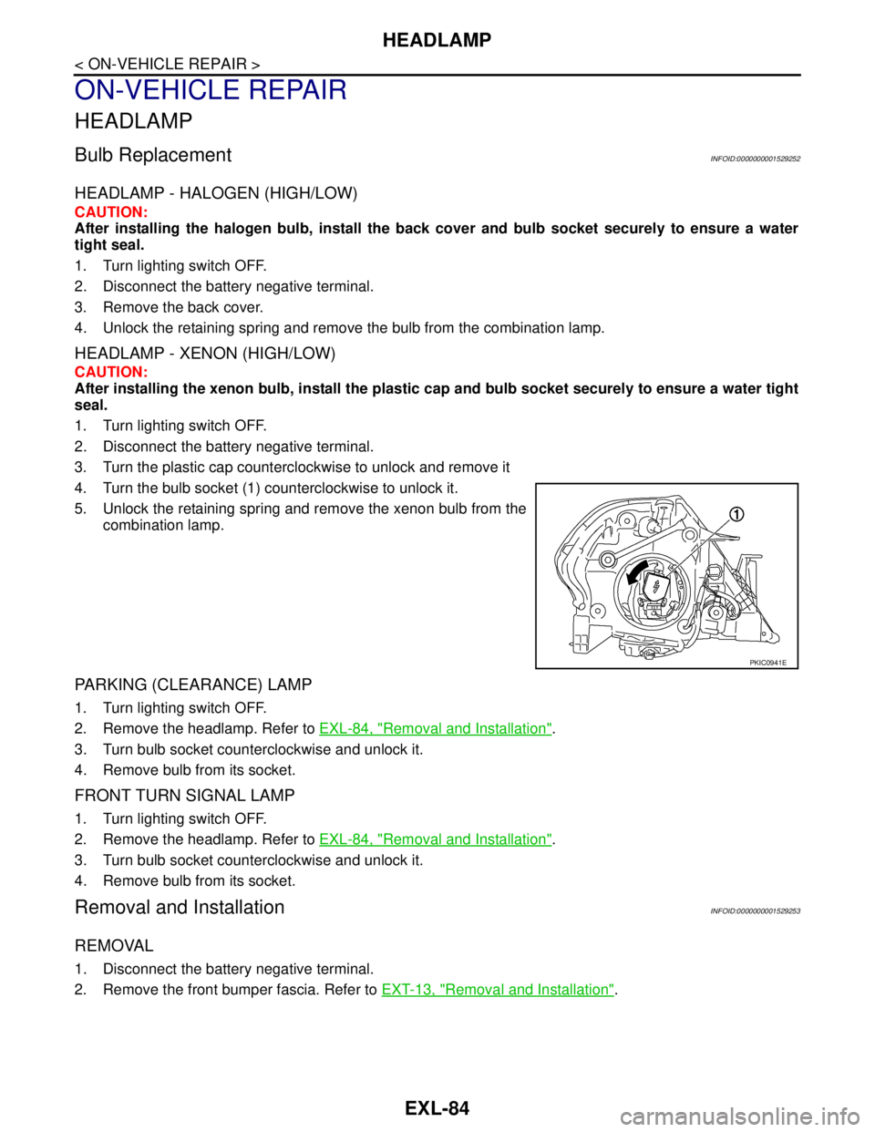
3. Turn the plastic cap counterclockwise to unlock and remove it
4. Turn the bulb socket (1) counterclockwise to unlock it.
5. Unlock the retaining spring and remove the xenon bulb from the
combination lamp.
PARKING (CLEARANCE) LAMP
1. Turn lighting switch OFF.
2. Remove the headlamp. Refer to EXL-84, "
Removal and Installation".
3. Turn bulb socket counterclockwise and unlock it.
4. Remove bulb from its socket.
FRONT TURN SIGNAL LAMP
1. Turn lighting switch OFF.
2. Remove the headlamp. Refer to EXL-84, "
Removal and Installation".
3. Turn bulb socket counterclockwise and unlock it.
4. Remove bulb from its socket.
Removal and InstallationINFOID:0000000001529253
REMOVAL
1. Disconnect the battery negative terminal.
2. Remove the front bumper fascia. Refer to EXT-13, "
Removal and Installation".
PKIC0941E
Page 3133 of 5883
TRUNK LID FINISHER
EXT-29
< ON-VEHICLE REPAIR >
C
D
E
F
G
H
I
J
L
MA
B
EXT
N
O
P
TRUNK LID FINISHER
Removal and InstallationINFOID:0000000001568938
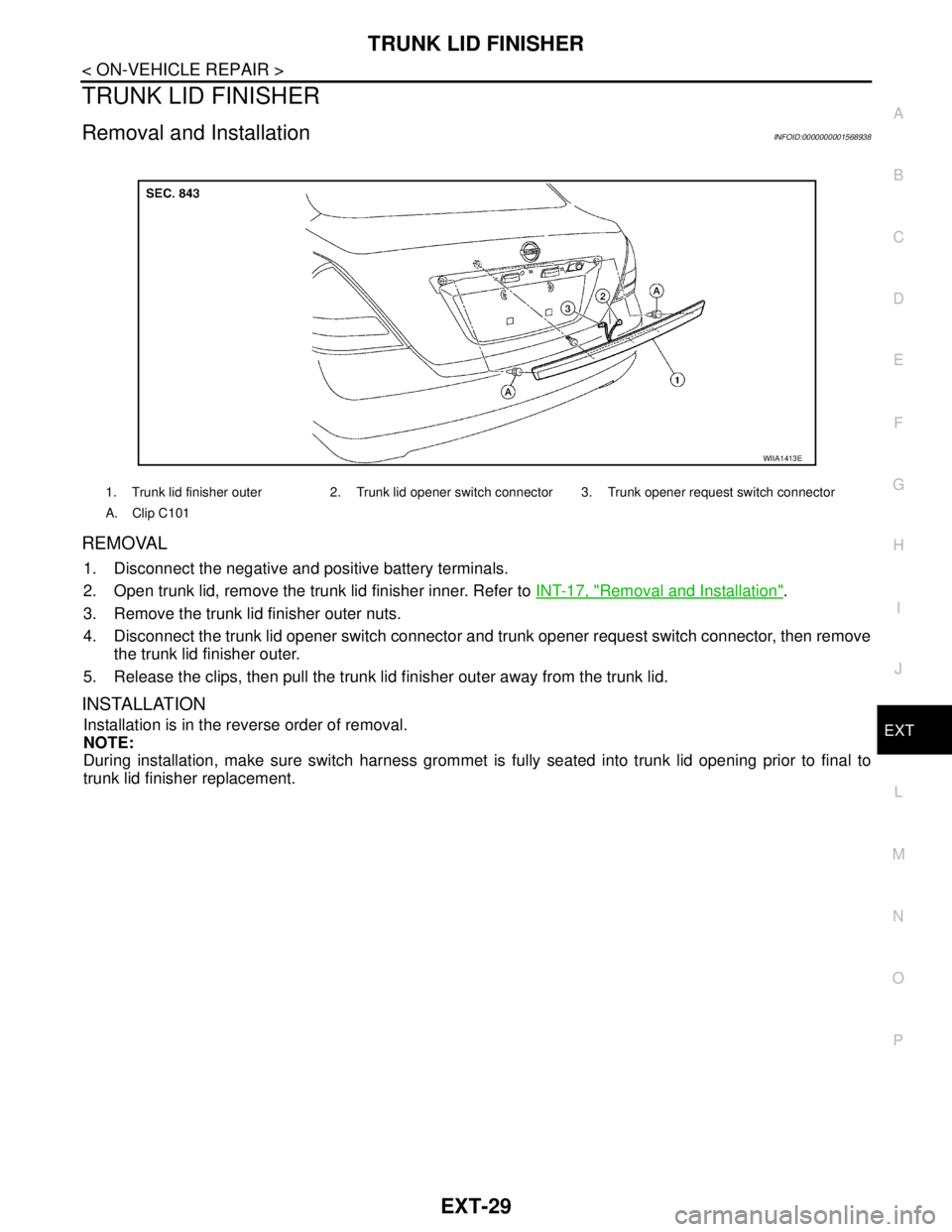
REMOVAL
1. Disconnect the negative and positive battery terminals.
2. Open trunk lid, remove the trunk lid finisher inner. Refer to INT-17, "
Removal and Installation".
3. Remove the trunk lid finisher outer nuts.
4. Disconnect the trunk lid opener switch connector and trunk opener request switch connector, then remove
the trunk lid finisher outer.
5. Release the clips, then pull the trunk lid finisher outer away from the trunk lid.
INSTALLATION
Installation is in the reverse order of removal.
NOTE:
During installation, make sure switch harness grommet is fully seated into trunk lid opening prior to final to
trunk lid finisher replacement.
1. Trunk lid finisher outer 2. Trunk lid opener switch connector 3. Trunk opener request switch connector
A. Clip C101
WIIA1413E
Page 3164 of 5883
FL-4
< ON-VEHICLE MAINTENANCE >
FUEL SYSTEM
ON-VEHICLE MAINTENANCE
FUEL SYSTEM
Checking Fuel LineINFOID:0000000001722976
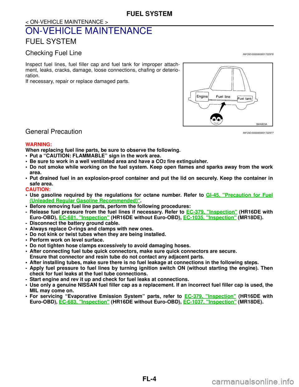
Inspect fuel lines, fuel filler cap and fuel tank for improper attach-
ment, leaks, cracks, damage, loose connections, chafing or deterio-
ration.
If necessary, repair or replace damaged parts.
General PrecautionINFOID:0000000001722977
WARNING:
When replacing fuel line parts, be sure to observe the following.
Put a “CAUTION: FLAMMABLE” sign in the work area.
Be sure to work in a well ventilated area and have a CO
2 fire extinguisher.
Do not smoke while working on the fuel system. Keep open flames and sparks away from the work
area.
Put drained fuel in an explosion-proof container and put the lid on securely. Keep the container in
safe area.
CAUTION:
Use gasoline required by the regulations for octane number. Refer to GI-45, "
Precaution for Fuel
(Unleaded Regular Gasoline Recommended)".
Before removing fuel line parts, perform the following procedures:
- Release fuel pressure from the fuel lines if necessary. Refer to EC-379, "
Inspection" (HR16DE with
Euro-OBD), EC-681, "
Inspection" (HR16DE without Euro-OBD), EC-1035, "Inspection" (MR18DE).
- Disconnect the battery ground cable.
Always replace O-rings and clamps with new ones.
Do not kink or twist tubes when they are being installed.
Perform work on level surface.
Do not tighten hose clamps excessively to avoid damaging hoses.
After connecting fuel tube quick connectors, make sure quick connectors are secure.
Ensure that connector and resin tube do not contact any adjacent parts.
After installing tubes, make sure there is no fuel leakage at connections in the following steps.
- Apply fuel pressure to fuel lines by turning ignition switch ON (without starting the engine). Then
check for fuel leaks at the fuel tube connections.
- Start engine and rev it up and check for fuel leaks at connections.
Use only a genuine NISSAN fuel filler cap as a replacement. If an incorrect fuel filler cap is used, the
MIL may come on.
For servicing “Evaporative Emission System” parts, refer to EC-379, "
Inspection" (HR16DE with
Euro-OBD), EC-683, "
Inspection" (HR16DE without Euro-OBD), EC-1037, "Inspection" (MR18DE).
SMA803A
Page 3246 of 5883
GI-52
< BASIC INSPECTION >
SERVICE INFORMATION FOR ELECTRICAL INCIDENT
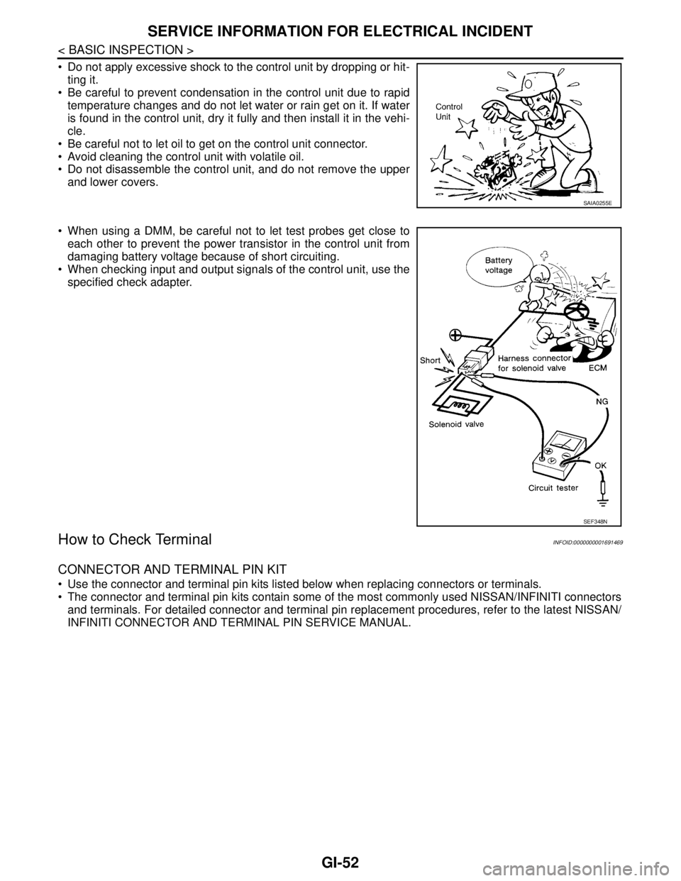
Do not apply excessive shock to the control unit by dropping or hit-
ting it.
Be careful to prevent condensation in the control unit due to rapid
temperature changes and do not let water or rain get on it. If water
is found in the control unit, dry it fully and then install it in the vehi-
cle.
Be careful not to let oil to get on the control unit connector.
Avoid cleaning the control unit with volatile oil.
Do not disassemble the control unit, and do not remove the upper
and lower covers.
When using a DMM, be careful not to let test probes get close to
each other to prevent the power transistor in the control unit from
damaging battery voltage because of short circuiting.
When checking input and output signals of the control unit, use the
specified check adapter.
How to Check TerminalINFOID:0000000001691469
CONNECTOR AND TERMINAL PIN KIT
Use the connector and terminal pin kits listed below when replacing connectors or terminals.
The connector and terminal pin kits contain some of the most commonly used NISSAN/INFINITI connectors
and terminals. For detailed connector and terminal pin replacement procedures, refer to the latest NISSAN/
INFINITI CONNECTOR AND TERMINAL PIN SERVICE MANUAL.
SAIA0255E
SEF348N
Page 3676 of 5883
INTERIOR ROOM LAMP
INL-25
< ON-VEHICLE REPAIR >
C
D
E
F
G
H
I
J
K
MA
B
INL
N
O
P
ON-VEHICLE REPAIR
INTERIOR ROOM LAMP
Removal and InstallationINFOID:0000000001726698
MAP LAMP
Removal
1. Disconnect the negative battery cable.
2. Insert a suitable tool and release the pawl, then remove map lamp from overhead console assembly.
3. Disconnect the connectors, then remove map lamp.
Installation
Installation is in the reverse order of removal.
Bulb Replacement
1. Disconnect the negative battery cable.
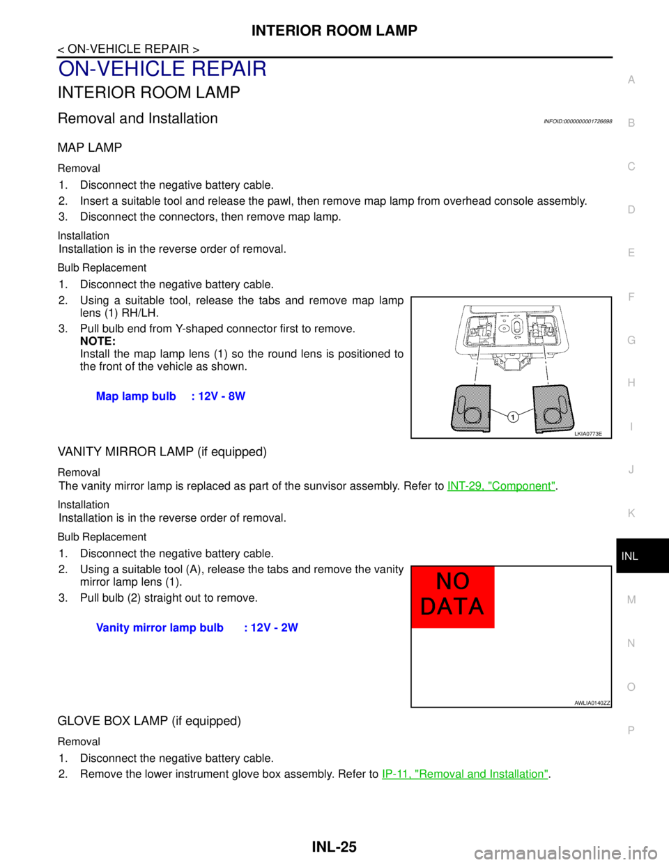
2. Using a suitable tool, release the tabs and remove map lamp
lens (1) RH/LH.
3. Pull bulb end from Y-shaped connector first to remove.
NOTE:
Install the map lamp lens (1) so the round lens is positioned to
the front of the vehicle as shown.
VANITY MIRROR LAMP (if equipped)
Removal
The vanity mirror lamp is replaced as part of the sunvisor assembly. Refer to INT-29, "Component".
Installation
Installation is in the reverse order of removal.
Bulb Replacement
1. Disconnect the negative battery cable.
2. Using a suitable tool (A), release the tabs and remove the vanity
mirror lamp lens (1).
3. Pull bulb (2) straight out to remove.
GLOVE BOX LAMP (if equipped)
Removal
1. Disconnect the negative battery cable.
2. Remove the lower instrument glove box assembly. Refer to IP-11, "
Removal and Installation". Map lamp bulb : 12V - 8W
LKIA0773E
Vanity mirror lamp bulb : 12V - 2W
AWLIA0140ZZ
Page 3677 of 5883
INL-26
< ON-VEHICLE REPAIR >
INTERIOR ROOM LAMP
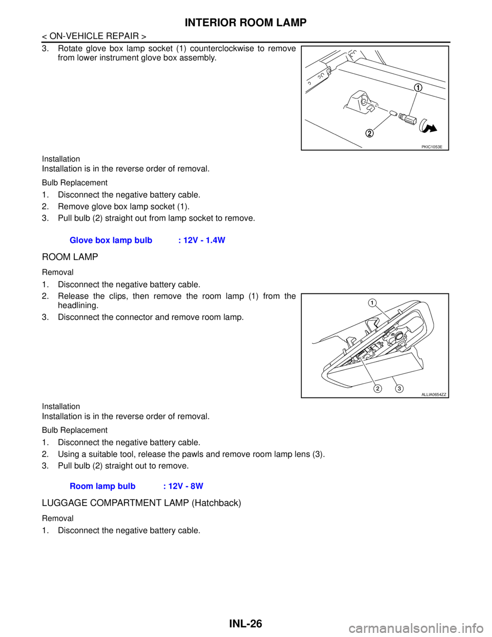
3. Rotate glove box lamp socket (1) counterclockwise to remove
from lower instrument glove box assembly.
Installation
Installation is in the reverse order of removal.
Bulb Replacement
1. Disconnect the negative battery cable.
2. Remove glove box lamp socket (1).
3. Pull bulb (2) straight out from lamp socket to remove.
ROOM LAMP
Removal
1. Disconnect the negative battery cable.
2. Release the clips, then remove the room lamp (1) from the
headlining.
3. Disconnect the connector and remove room lamp.
Installation
Installation is in the reverse order of removal.
Bulb Replacement
1. Disconnect the negative battery cable.
2. Using a suitable tool, release the pawls and remove room lamp lens (3).
3. Pull bulb (2) straight out to remove.
LUGGAGE COMPARTMENT LAMP (Hatchback)
Removal
1. Disconnect the negative battery cable.
PKIC1053E
Glove box lamp bulb : 12V - 1.4W
ALLIA0654ZZ
Room lamp bulb : 12V - 8W