battery replacement NISSAN TIIDA 2007 Service User Guide
[x] Cancel search | Manufacturer: NISSAN, Model Year: 2007, Model line: TIIDA, Model: NISSAN TIIDA 2007Pages: 5883, PDF Size: 78.95 MB
Page 3678 of 5883
INTERIOR ROOM LAMP
INL-27
< ON-VEHICLE REPAIR >
C
D
E
F
G
H
I
J
K
MA
B
INL
N
O
P
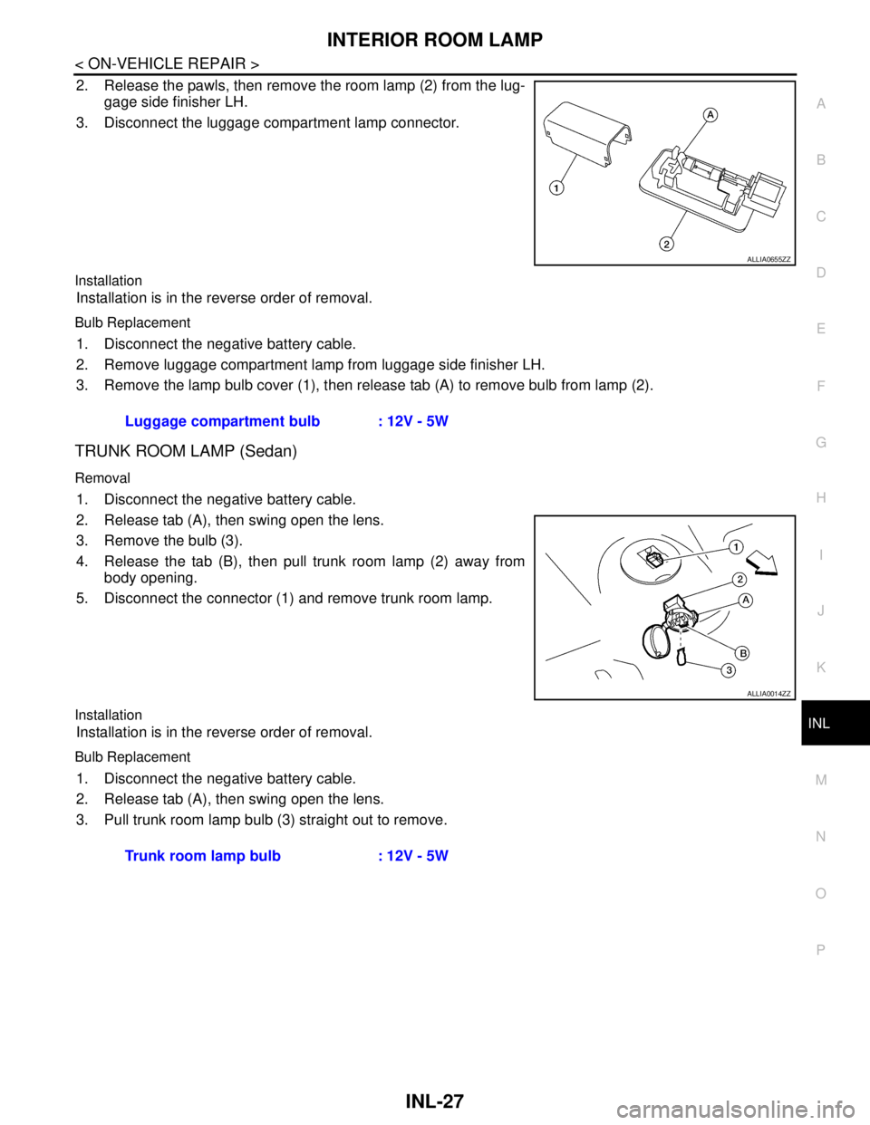
2. Release the pawls, then remove the room lamp (2) from the lug-
gage side finisher LH.
3. Disconnect the luggage compartment lamp connector.
Installation
Installation is in the reverse order of removal.
Bulb Replacement
1. Disconnect the negative battery cable.
2. Remove luggage compartment lamp from luggage side finisher LH.
3. Remove the lamp bulb cover (1), then release tab (A) to remove bulb from lamp (2).
TRUNK ROOM LAMP (Sedan)
Removal
1. Disconnect the negative battery cable.
2. Release tab (A), then swing open the lens.
3. Remove the bulb (3).
4. Release the tab (B), then pull trunk room lamp (2) away from
body opening.
5. Disconnect the connector (1) and remove trunk room lamp.
Installation
Installation is in the reverse order of removal.
Bulb Replacement
1. Disconnect the negative battery cable.
2. Release tab (A), then swing open the lens.
3. Pull trunk room lamp bulb (3) straight out to remove.
ALLIA0655ZZ
Luggage compartment bulb : 12V - 5W
ALLIA0014ZZ
Trunk room lamp bulb : 12V - 5W
Page 4754 of 5883
SIDE CURTAIN AIR BAG MODULE
SR-11
< ON-VEHICLE REPAIR >
C
D
E
F
G
I
J
K
L
MA
B
SR
N
O
P
When servicing the SRS, do not work from directly in front of air bag module.
Always place the curtain air bag module with deployment side facing upward.
Do not reuse center pillar upper garnish if removed.
CAUTION:
Before servicing SRS, turn the ignition switch OFF, disconnect both battery cables and wait at least
3 minutes.
Do not use old bolts after removal; replace with new bolts.
Do not insert any foreign objects (screwdriver, etc.) into air bag module or harness connectors.
Do not disassemble air bag module.
Do not expose the side curtain air bag module to temperatures exceeding 90°C (194°F).
Replace the side curtain air bag module if it has been dropped
or sustained an impact.
Do not allow oil, grease or water to come in contact with the
side curtain air bag module.
Do not attempt to repair or replace damaged direct-connect
SRS component connectors. If a direct-connect harness con-
nector is damaged, the harness must be replaced.
1. Disconnect both the negative and positive battery cables, then wait at least 3 minutes.
2. Remove the headlining. Refer to INT-29, "
Component".
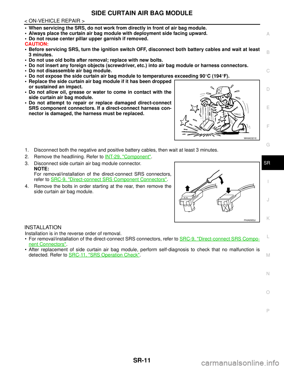
3. Disconnect side curtain air bag module connector.
NOTE:
For removal/installation of the direct-connect SRS connectors,
refer to SRC-9, "
Direct-connect SRS Component Connectors".
4. Remove the bolts in order starting at the rear, then remove the
side curtain air bag module.
INSTALLATION
Installation is in the reverse order of removal.
For removal/installation of the direct-connect SRS connectors, refer to SRC-9, "
Direct-connect SRS Compo-
nent Connectors".
After replacement of side curtain air bag module, perform self-diagnosis to check that no malfunction is
detected. Refer to SRC-11, "
SRS Operation Check".
WHIA0321E
PHIA0953J
Page 4756 of 5883
PASSENGER AIR BAG DEACTIVATION SWITCH
SR-13
< ON-VEHICLE REPAIR >
C
D
E
F
G
I
J
K
L
MA
B
SR
N
O
P
PASSENGER AIR BAG DEACTIVATION SWITCH
Passenger Air Bag Deactivation SwitchINFOID:0000000001404301
REMOVAL
CAUTION:
Before servicing SRS, turn ingition switch OFF, disconnect both battery cables, then wait at least 3
minutes.
1. Disconnect the negative and positive battery cables, then wait at least 3 minutes.
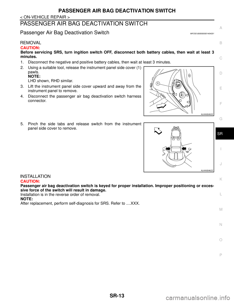
2. Using a suitable tool, release the instrument panel side cover (1)
pawls.
NOTE:
LHD shown, RHD similar.
3. Lift the instrument panel side cover upward and away from the
instrument panel to remove.
4. Disconnect the passenger air bag deactivation switch harness
connector.
5. Pinch the side tabs and release switch from the instrument
panel side cover to remove.
INSTALLATION
CAUTION:
Passenger air bag deactivation switch is keyed for proper installation. Improper positioning or exces-
sive force of the switch will result in damage.
Installation is in the reverse order of removal.
NOTE:
After replacement, perform self-diagnosis for SRS. Refer to ....XXX.
ALHIA0045ZZ
ALHIA0046ZZ