drain bolt NISSAN TIIDA 2007 Service Repair Manual
[x] Cancel search | Manufacturer: NISSAN, Model Year: 2007, Model line: TIIDA, Model: NISSAN TIIDA 2007Pages: 5883, PDF Size: 78.95 MB
Page 206 of 5883

BR-14
< ON-VEHICLE REPAIR >
BRAKE TUBE AND HOSE
BRAKE TUBE AND HOSE
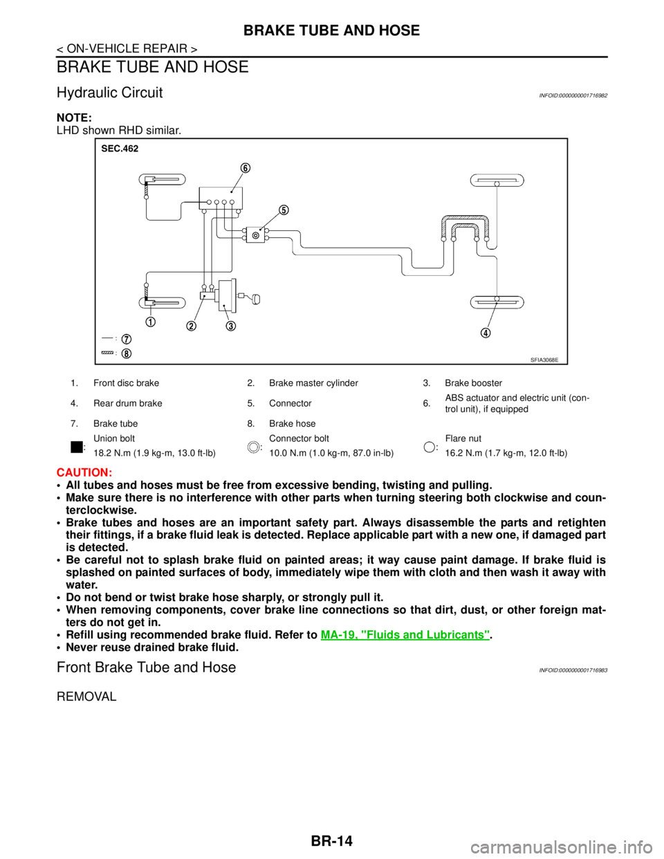
Hydraulic CircuitINFOID:0000000001716982
NOTE:
LHD shown RHD similar.
CAUTION:
All tubes and hoses must be free from excessive bending, twisting and pulling.
Make sure there is no interference with other parts when turning steering both clockwise and coun-
terclockwise.
Brake tubes and hoses are an important safety part. Always disassemble the parts and retighten
their fittings, if a brake fluid leak is detected. Replace applicable part with a new one, if damaged part
is detected.
Be careful not to splash brake fluid on painted areas; it way cause paint damage. If brake fluid is
splashed on painted surfaces of body, immediately wipe them with cloth and then wash it away with
water.
Do not bend or twist brake hose sharply, or strongly pull it.
When removing components, cover brake line connections so that dirt, dust, or other foreign mat-
ters do not get in.
Refill using recommended brake fluid. Refer to MA-19, "
Fluids and Lubricants".
Never reuse drained brake fluid.
Front Brake Tube and HoseINFOID:0000000001716983
REMOVAL
1. Front disc brake 2. Brake master cylinder 3. Brake booster
4. Rear drum brake 5. Connector 6.ABS actuator and electric unit (con-
trol unit), if equipped
7. Brake tube 8. Brake hose
:Union bolt
:Connector bolt
:Flare nut
18.2 N.m (1.9 kg-m, 13.0 ft-lb) 10.0 N.m (1.0 kg-m, 87.0 in-lb) 16.2 N.m (1.7 kg-m, 12.0 ft-lb)
SFIA3068E
Page 207 of 5883

BRAKE TUBE AND HOSE
BR-15
< ON-VEHICLE REPAIR >
C
D
E
G
H
I
J
K
L
MA
B
BR
N
O
P
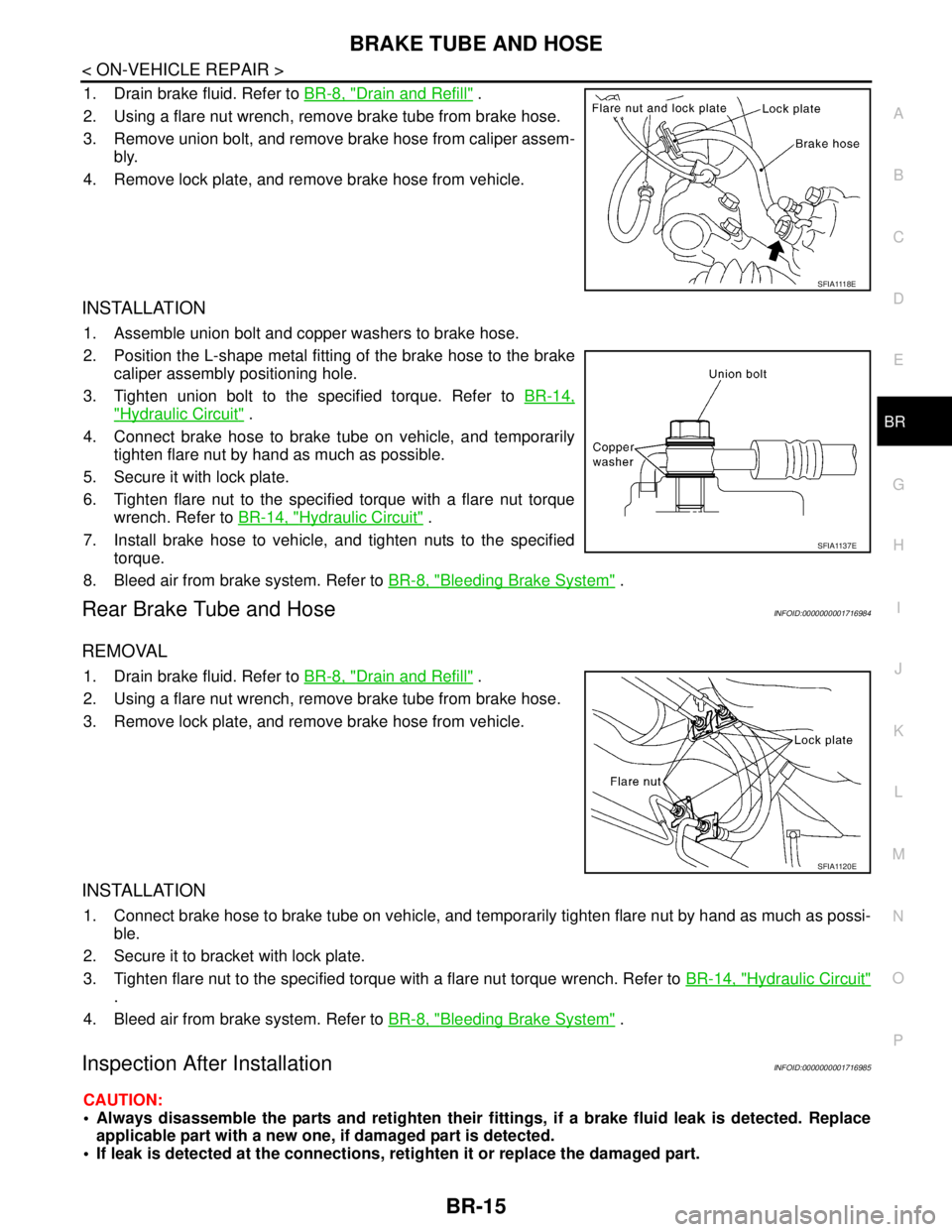
1. Drain brake fluid. Refer to BR-8, "Drain and Refill" .
2. Using a flare nut wrench, remove brake tube from brake hose.
3. Remove union bolt, and remove brake hose from caliper assem-
bly.
4. Remove lock plate, and remove brake hose from vehicle.
INSTALLATION
1. Assemble union bolt and copper washers to brake hose.
2. Position the L-shape metal fitting of the brake hose to the brake
caliper assembly positioning hole.
3. Tighten union bolt to the specified torque. Refer to BR-14,
"Hydraulic Circuit" .
4. Connect brake hose to brake tube on vehicle, and temporarily
tighten flare nut by hand as much as possible.
5. Secure it with lock plate.
6. Tighten flare nut to the specified torque with a flare nut torque
wrench. Refer to BR-14, "
Hydraulic Circuit" .
7. Install brake hose to vehicle, and tighten nuts to the specified
torque.
8. Bleed air from brake system. Refer to BR-8, "
Bleeding Brake System" .
Rear Brake Tube and HoseINFOID:0000000001716984
REMOVAL
1. Drain brake fluid. Refer to BR-8, "Drain and Refill" .
2. Using a flare nut wrench, remove brake tube from brake hose.
3. Remove lock plate, and remove brake hose from vehicle.
INSTALLATION
1. Connect brake hose to brake tube on vehicle, and temporarily tighten flare nut by hand as much as possi-
ble.
2. Secure it to bracket with lock plate.
3. Tighten flare nut to the specified torque with a flare nut torque wrench. Refer to BR-14, "
Hydraulic Circuit"
.
4. Bleed air from brake system. Refer to BR-8, "
Bleeding Brake System" .
Inspection After InstallationINFOID:0000000001716985
CAUTION:
Always disassemble the parts and retighten their fittings, if a brake fluid leak is detected. Replace
applicable part with a new one, if damaged part is detected.
If leak is detected at the connections, retighten it or replace the damaged part.
S F I A 111 8 E
SFIA1137E
SFIA1120E
Page 217 of 5883

FRONT DISC BRAKE
BR-25
< ON-VEHICLE REPAIR >
C
D
E
G
H
I
J
K
L
MA
B
BR
N
O
P
2. Remove sliding pin bolt (lower side).
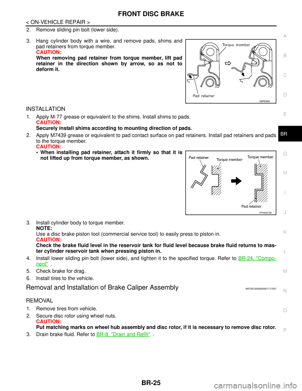
3. Hang cylinder body with a wire, and remove pads, shims and
pad retainers from torque member.
CAUTION:
When removing pad retainer from torque member, lift pad
retainer in the direction shown by arrow, so as not to
deform it.
INSTALLATION
1. Apply M-77 grease or equivalent to the shims. Install shims to pads.
CAUTION:
Securely install shims according to mounting direction of pads.
2. Apply M7439 grease or equivalent to pad contact surface on pad retainers. Install pad retainers and pads
to the torque member.
CAUTION:
When installing pad retainer, attach it firmly so that it is
not lifted up from torque member, as shown.
3. Install cylinder body to torque member.
NOTE:
Use a disc brake piston tool (commercial service tool) to easily press to piston in.
CAUTION:
Check the brake fluid level in the reservoir tank for fluid level because brake fluid returns to mas-
ter cylinder reservoir tank when pressing piston in.
4. Install lower sliding pin bolt (lower side), and tighten it to the specified torque. Refer to BR-24, "
Compo-
nent" .
5. Check brake for drag.
6. Install tires to the vehicle.
Removal and Installation of Brake Caliper AssemblyINFOID:0000000001717007
REMOVAL
1. Remove tires from vehicle.
2. Secure disc rotor using wheel nuts.
CAUTION:
Put matching marks on wheel hub assembly and disc rotor, if it is necessary to remove disc rotor.
3. Drain brake fluid. Refer to BR-8, "
Drain and Refill" .
SBR556E
PFIA0273E
Page 221 of 5883

REAR DISC BRAKE
BR-29
< ON-VEHICLE REPAIR >
C
D
E
G
H
I
J
K
L
MA
B
BR
N
O
P
3. Drain brake fluid. Refer to BR-8, "Bleeding Brake System".
4. Remove connecting bolt and torque member bolts using power tool, and remove cylinder body.
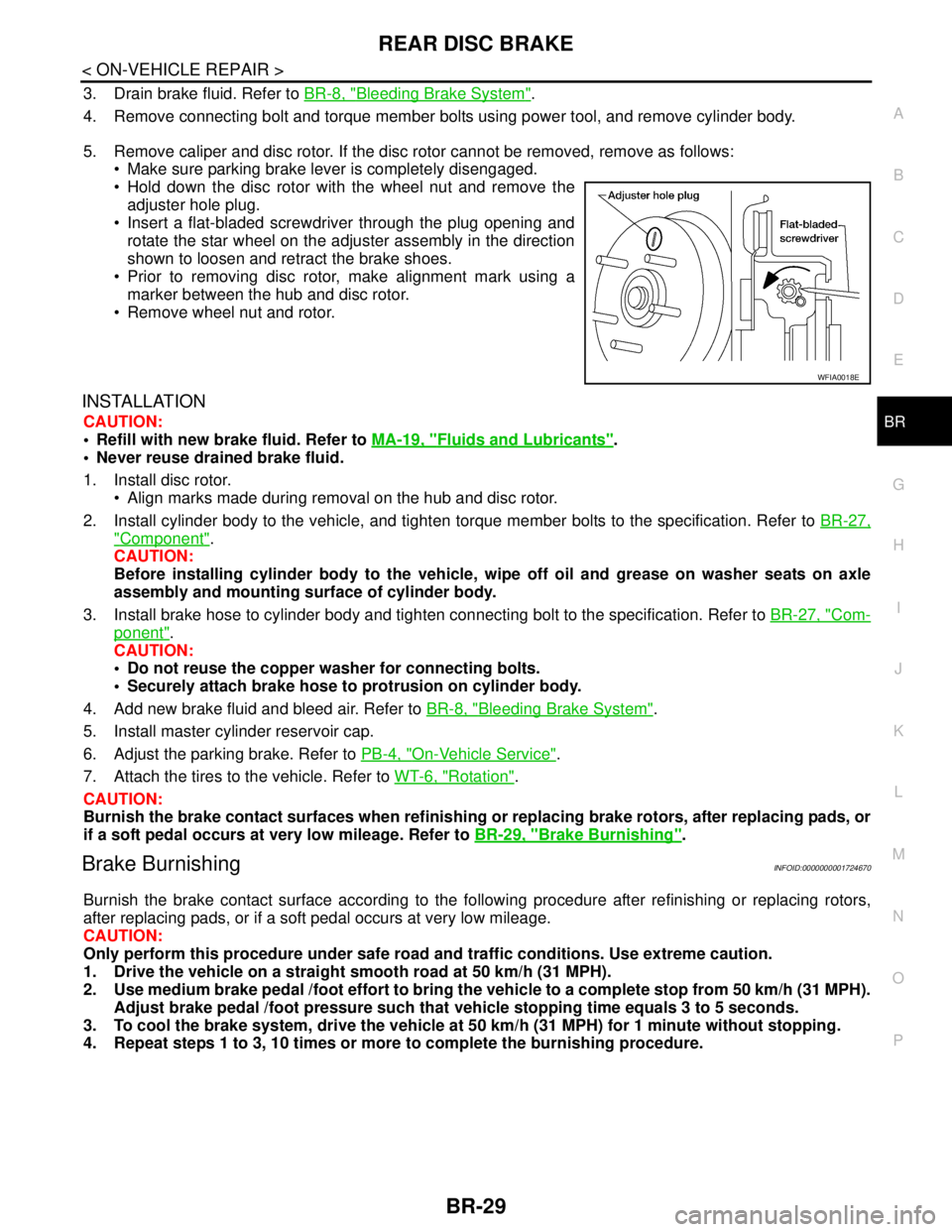
5. Remove caliper and disc rotor. If the disc rotor cannot be removed, remove as follows:
Make sure parking brake lever is completely disengaged.
Hold down the disc rotor with the wheel nut and remove the
adjuster hole plug.
Insert a flat-bladed screwdriver through the plug opening and
rotate the star wheel on the adjuster assembly in the direction
shown to loosen and retract the brake shoes.
Prior to removing disc rotor, make alignment mark using a
marker between the hub and disc rotor.
Remove wheel nut and rotor.
INSTALLATION
CAUTION:
Refill with new brake fluid. Refer to MA-19, "
Fluids and Lubricants".
Never reuse drained brake fluid.
1. Install disc rotor.
Align marks made during removal on the hub and disc rotor.
2. Install cylinder body to the vehicle, and tighten torque member bolts to the specification. Refer to BR-27,
"Component".
CAUTION:
Before installing cylinder body to the vehicle, wipe off oil and grease on washer seats on axle
assembly and mounting surface of cylinder body.
3. Install brake hose to cylinder body and tighten connecting bolt to the specification. Refer to BR-27, "
Com-
ponent".
CAUTION:
Do not reuse the copper washer for connecting bolts.
Securely attach brake hose to protrusion on cylinder body.
4. Add new brake fluid and bleed air. Refer to BR-8, "
Bleeding Brake System".
5. Install master cylinder reservoir cap.
6. Adjust the parking brake. Refer to PB-4, "
On-Vehicle Service".
7. Attach the tires to the vehicle. Refer to WT-6, "
Rotation".
CAUTION:
Burnish the brake contact surfaces when refinishing or replacing brake rotors, after replacing pads, or
if a soft pedal occurs at very low mileage. Refer to BR-29, "
Brake Burnishing".
Brake BurnishingINFOID:0000000001724670
Burnish the brake contact surface according to the following procedure after refinishing or replacing rotors,
after replacing pads, or if a soft pedal occurs at very low mileage.
CAUTION:
Only perform this procedure under safe road and traffic conditions. Use extreme caution.
1. Drive the vehicle on a straight smooth road at 50 km/h (31 MPH).
2. Use medium brake pedal /foot effort to bring the vehicle to a complete stop from 50 km/h (31 MPH).
Adjust brake pedal /foot pressure such that vehicle stopping time equals 3 to 5 seconds.
3. To cool the brake system, drive the vehicle at 50 km/h (31 MPH) for 1 minute without stopping.
4. Repeat steps 1 to 3, 10 times or more to complete the burnishing procedure.
WFIA0018E
Page 498 of 5883
![NISSAN TIIDA 2007 Service Repair Manual RADIATOR
CO-17
< ON-VEHICLE REPAIR >[HR16DE]
C
D
E
F
G
H
I
J
K
L
MA
CO
N
P O
Do not remove radiator cap when the engine is hot. Serious burns could occur from high-pressure
engine coolant escaping fro NISSAN TIIDA 2007 Service Repair Manual RADIATOR
CO-17
< ON-VEHICLE REPAIR >[HR16DE]
C
D
E
F
G
H
I
J
K
L
MA
CO
N
P O
Do not remove radiator cap when the engine is hot. Serious burns could occur from high-pressure
engine coolant escaping fro](/img/5/57395/w960_57395-497.png)
RADIATOR
CO-17
< ON-VEHICLE REPAIR >[HR16DE]
C
D
E
F
G
H
I
J
K
L
MA
CO
N
P O
Do not remove radiator cap when the engine is hot. Serious burns could occur from high-pressure
engine coolant escaping from radiator. Wrap a thick cloth around the cap. Slowly turn it a quarter of a
turn to release built-up pressure. Carefully remove radiator cap by turning it all the way.
REMOVAL
1. Drain engine coolant from radiator. Refer to CO-11, "Changing Engine Coolant".
CAUTION:
Perform this step when engine is cold.
Do not spill engine coolant on drive belt.
2. Remove air duct (inlet). Refer to EM-27, "
Exploded View".
3. Remove reservoir tank as follows:
a. Disconnect reservoir tank hose.
b. Release the tab (A) in the direction shown by the arrow ( ).
c. Lift up while removing the reservoir tank hose, and remove it.
4. Disconnect harness connector from fan motor, and move harness aside.
5. Disconnect A/T fluid cooler hoses if equipped.
Install plug to avoid leakage of A/T fluid if equipped.
6. Remove radiator hoses (upper and lower).
7. Remove radiator core support cover.
8. Remove radiator core support (upper) bolts, bolts of stationary
part on the radiator core support side and clip. Lift radiator
assembly (1) from radiator (upper) mount part of radiator core
support (upper) (2).
9. Move radiator assembly (1) to the rearward direction of vehicle,
and then lift it upward to remove.
CAUTION:
Do not damage or scratch A/C condenser if equipped and
radiator core when removing.
INSTALLATION
Installation is the reverse order of removal.
CAUTION:
Do not damage or scratch A/C condenser if equipped and radiator core when removing.
INSPECTION AFTER INSTALLATION
Check for leaks of engine coolant.
Start and warm up engine. Visually check if there is no leaks of engine coolant and A/T fluid if equipped.
PBIC3800E
PBIC3805E
Page 501 of 5883
![NISSAN TIIDA 2007 Service Repair Manual CO-20
< ON-VEHICLE REPAIR >[HR16DE]
WATER PUMP
WATER PUMP
Exploded ViewINFOID:0000000001381568
Removal and InstallationINFOID:0000000001381569
REMOVAL
1. Drain engine coolant from radiator. Refer to C NISSAN TIIDA 2007 Service Repair Manual CO-20
< ON-VEHICLE REPAIR >[HR16DE]
WATER PUMP
WATER PUMP
Exploded ViewINFOID:0000000001381568
Removal and InstallationINFOID:0000000001381569
REMOVAL
1. Drain engine coolant from radiator. Refer to C](/img/5/57395/w960_57395-500.png)
CO-20
< ON-VEHICLE REPAIR >[HR16DE]
WATER PUMP
WATER PUMP
Exploded ViewINFOID:0000000001381568
Removal and InstallationINFOID:0000000001381569
REMOVAL
1. Drain engine coolant from radiator. Refer to CO-11, "Changing Engine Coolant".
CAUTION:
Perform this step when the engine is cold.
Never spill engine coolant on drive belts.
2. Steer front wheel to the right.
3. Remove front fender protector (RH). Refer to EXT-22, "
Removal and Installation".
4. Loosen mounting bolts of water pump pulley before loosening belt tension of drive belt.
5. Remove drive belt. Refer to EM-16, "
Removal and Installation".
6. Remove water pump pulley.
7. Remove water pump.
Loosen mounting bolts in reverse order as shown.
Engine coolant will leak from cylinder block, so have a recep-
tacle ready below.
CAUTION:
Handle water pump vane so that it does not contact any
other parts.
Water pump cannot be disassembled and should be
replaced as a unit.
INSTALLATION
Installation is in the reverse order of removal.
Water pump.
1. Gasket 2. Water pump 3. Water pump pulley
PBIC3807E
KBIA3393J
Page 545 of 5883
![NISSAN TIIDA 2007 Service Repair Manual CO-64
< ON-VEHICLE REPAIR >[K9K]
COOLING FAN
COOLING FAN
Exploded ViewINFOID:0000000001381594
Removal and InstallationINFOID:0000000001381595
REMOVAL
1. Remove engine undercover using power tool.
2. D NISSAN TIIDA 2007 Service Repair Manual CO-64
< ON-VEHICLE REPAIR >[K9K]
COOLING FAN
COOLING FAN
Exploded ViewINFOID:0000000001381594
Removal and InstallationINFOID:0000000001381595
REMOVAL
1. Remove engine undercover using power tool.
2. D](/img/5/57395/w960_57395-544.png)
CO-64
< ON-VEHICLE REPAIR >[K9K]
COOLING FAN
COOLING FAN
Exploded ViewINFOID:0000000001381594
Removal and InstallationINFOID:0000000001381595
REMOVAL
1. Remove engine undercover using power tool.
2. Drain engine coolant. Refer to CO-58, "
Draining".
3. Remove air duct (inlet). Refer to EM-269, "
Exploded View".
4. Disconnect reservoir tank hoses and remove reservoir tank.
5. Remove radiator hose (upper). Refer to CO-62, "
Exploded View".
6. Disconnect harness connector for cooling fan control module and fan motor, and move harness aside.
7. Remove cooling fan assembly.
CAUTION:
Be careful not to damage or scratch on radiator core.
INSTALLATION
Installation is in the reverse order of removal.
CAUTION:
Only use genuine parts for fan shroud bolt and observe the specified torque (to prevent radiator from
being damaged).
NOTE:
Cooling fan is controlled by ECM. For details, refer to CO-52, "
EngineCoolingSystem".
1. Fan shroud 2. Cooling fan control module 3. Fan motor
4. Cooling fan
A. Reverse screw
: Vehicle front
ALBIA0424GB
Page 2655 of 5883
![NISSAN TIIDA 2007 Service Repair Manual EM-8
< PRECAUTION >[HR16DE]
PRECAUTIONS
3. Disconnect both battery cables. The steering lock will remain released and the steering wheel can be
rotated.
4. Perform the necessary repair operation.
5. W NISSAN TIIDA 2007 Service Repair Manual EM-8
< PRECAUTION >[HR16DE]
PRECAUTIONS
3. Disconnect both battery cables. The steering lock will remain released and the steering wheel can be
rotated.
4. Perform the necessary repair operation.
5. W](/img/5/57395/w960_57395-2654.png)
EM-8
< PRECAUTION >[HR16DE]
PRECAUTIONS
3. Disconnect both battery cables. The steering lock will remain released and the steering wheel can be
rotated.
4. Perform the necessary repair operation.
5. When the repair work is completed, return the ignition switch to the ″LOCK″ position before connecting
the battery cables. (At this time, the steering lock mechanism will engage.)
6. Perform a self-diagnosis check of all control units using CONSULT-II.
Precaution for Drain CoolantINFOID:0000000001527635
Drain coolant when engine is cooled.
Precaution for Disconnecting Fuel PipingINFOID:0000000001527636
Before starting work, make sure no fire or spark producing items are in the work area.
Release fuel pressure before disassembly.
After disconnecting pipes, plug openings to stop fuel leakage.
Precaution for Removal and DisassemblyINFOID:0000000001527637
When instructed to use special service tools, use the specified tools. Always be careful to work safely, avoid
forceful or uninstructed operations.
Exercise maximum care to avoid damage to mating or sliding surfaces.
Cover openings of engine system with tape or the equivalent, if necessary, to seal out foreign materials.
Mark and arrange disassembly parts in an organized way for easy troubleshooting and assembly.
When loosening nuts and bolts, as a basic rule, start with the one furthest outside, then the one diagonally
opposite, and so on. If the order of loosening is specified, do exactly as specified. Power tools may be used
where noted in the step.
Precaution for Inspection, Repair and ReplacementINFOID:0000000001527638
Before repairing or replacing, thoroughly inspect parts. Inspect new replacement parts in the same way, and
replace if necessary.
Precaution for Assembly and InstallationINFOID:0000000001527639
Use torque wrench to tighten bolts or nuts to specification.
When tightening nuts and bolts, as a basic rule, equally tighten in several different steps starting with the
ones in center, then ones on inside and outside diagonally in this order. If the order of tightening is specified,
do exactly as specified.
Replace with new gasket, packing, oil seal or O-ring.
Thoroughly wash, clean, and air-blow each part. Carefully check oil or coolant passages for any restriction
and blockage.
Avoid damaging sliding or mating surfaces. Completely remove foreign materials such as cloth lint or dust.
Before assembly, oil sliding surfaces well.
Release air within route after draining coolant.
Before starting engine, apply fuel pressure to fuel lines with turning ignition switch ON (with engine stopped).
Then make sure that there are no leaks at fuel line connections.
After repairing, start engine and increase engine speed to check coolant, fuel, oil, and exhaust systems for
leakage.
Parts Requiring Angular TighteningINFOID:0000000001527640
Use an angle wrench for the final tightening of the following engine parts:
- Cylinder head bolts
- Camshaft sprocket (INT)
- Main bearing cap bolts
- Connecting rod cap nuts
- Crankshaft pulley bolt (No angle wrench is required as the bolt flange is provided with notches for angular
tightening)
Do not use a torque value for final tightening. Tool number : KV10112100 (BT-8653-A)
Page 2687 of 5883
![NISSAN TIIDA 2007 Service Repair Manual EM-40
< ON-VEHICLE REPAIR >[HR16DE]
OIL PAN (LOWER)
OIL PAN (LOWER)
Exploded ViewINFOID:0000000001381406
Removal and InstallationINFOID:0000000001381407
REMOVAL
1. Drain engine oil. Refer to LU-7, "Dr NISSAN TIIDA 2007 Service Repair Manual EM-40
< ON-VEHICLE REPAIR >[HR16DE]
OIL PAN (LOWER)
OIL PAN (LOWER)
Exploded ViewINFOID:0000000001381406
Removal and InstallationINFOID:0000000001381407
REMOVAL
1. Drain engine oil. Refer to LU-7, "Dr](/img/5/57395/w960_57395-2686.png)
EM-40
< ON-VEHICLE REPAIR >[HR16DE]
OIL PAN (LOWER)
OIL PAN (LOWER)
Exploded ViewINFOID:0000000001381406
Removal and InstallationINFOID:0000000001381407
REMOVAL
1. Drain engine oil. Refer to LU-7, "Draining".
2. Remove the oil pan (lower) with the following procedure.
a. Loosen bolts in the reverse of the order shown.
b. Insert the seal cutter [SST: KV10111100] between oil pan
(upper) and oil pan (lower).
CAUTION:
Be careful not to damage the mating surface.
A more adhesive liquid gasket is applied compared to pre-
vious types when shipped, so it should not be forced off
using a flat- bladed screwdriver, etc.
1. Rear oil seal 2. O-ring 3. Oil pan (upper)
4. Chain tensioner 5. Oil pump drive chain 6. Crankshaft sprocket
7. Oil pump sprocket 8. Oil pan drain plug 9. Washer
10. Oil pan (lower) 11. Oil filter stud bolt 12. Oil filter
13. Oil level sensor
A. Refer to EM-50
B. Refer to LU-9C. Oil pan side
JPBIA0553GB
: Engine front
PBIC4345E
Page 2688 of 5883
![NISSAN TIIDA 2007 Service Repair Manual OIL PAN (LOWER)
EM-41
< ON-VEHICLE REPAIR >[HR16DE]
C
D
E
F
G
H
I
J
K
L
MA
EM
N
P O
INSTALLATION
1. Install oil pan (lower) with the following procedure.
a. Use scraper to remove old liquid gasket fro NISSAN TIIDA 2007 Service Repair Manual OIL PAN (LOWER)
EM-41
< ON-VEHICLE REPAIR >[HR16DE]
C
D
E
F
G
H
I
J
K
L
MA
EM
N
P O
INSTALLATION
1. Install oil pan (lower) with the following procedure.
a. Use scraper to remove old liquid gasket fro](/img/5/57395/w960_57395-2687.png)
OIL PAN (LOWER)
EM-41
< ON-VEHICLE REPAIR >[HR16DE]
C
D
E
F
G
H
I
J
K
L
MA
EM
N
P O
INSTALLATION
1. Install oil pan (lower) with the following procedure.
a. Use scraper to remove old liquid gasket from mating surfaces.
Also remove the old liquid gasket from mating surface of oil pan (upper).
Remove old liquid gasket from the bolt holes and threads.
CAUTION:
Never scratch or damage the mating surfaces when cleaning off old liquid gasket.
b. Apply a continuous bead of liquid gasket (A) with the tube
presser (commercial service tool) to areas shown.
Use Genuine Liquid Gasket or equivalent.
CAUTION:
Attaching should be done within 5 minutes after coating.
c. Tighten bolts in the numerical order shown in the figure.
2. Install oil pan drain plug.
For installation direction of washer. Refer to EM-40, "
Exploded View".
3. Install in the reverse order of removal, for the rest of parts.
CAUTION:
Pour engine oil at least 30 minutes after oil pan is installed.
InspectionINFOID:0000000001381408
INSPECTION AFTER INSTALLATION
1. Check the engine oil level and adjust engine oil. Refer to LU-6, "Inspection".
2. Start engine, and check there is no leak of engine oil.
3. Stop engine and wait for 10 minutes.
4. Check the engine oil level again. Refer to LU-6, "
Inspection".
: Engine out side
PBIC5006E
: Engine front
PBIC4345E