exterior light NISSAN TIIDA 2007 Service Repair Manual
[x] Cancel search | Manufacturer: NISSAN, Model Year: 2007, Model line: TIIDA, Model: NISSAN TIIDA 2007Pages: 5883, PDF Size: 78.95 MB
Page 1 of 5883
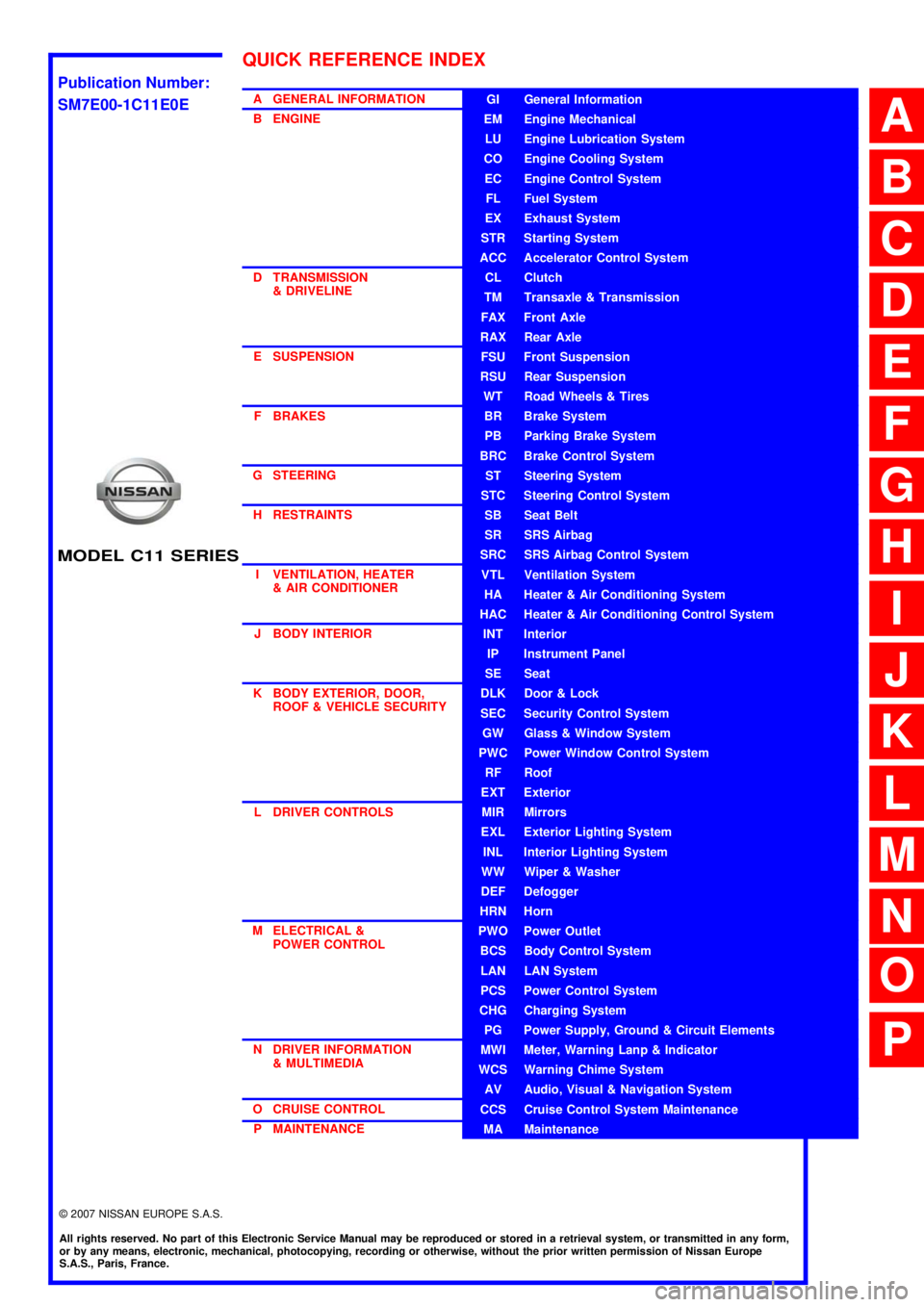
MODEL C11 SERIES
2007 NISSAN EUROPE S.A.S.
All rights reserved. No part of this Electronic Service Manual may be reproduced or stored in a retrieval system, or transmitted in any form,
or by any means, electronic, mechanical, photocopying, recording or otherwise, without the prior written permission of Nissan Europe
S.A.S., Paris, France.
A GENERAL INFORMATION
B ENGINE
D TRANSMISSION& DRIVELINE
E SUSPENSION F BRAKES
G STEERING H RESTRAINTS
I VENTILATION, HEATER & AIR CONDITIONER
J BODY INTERIOR
K BODY EXTERIOR, DOOR, ROOF & VEHICLE SECURITY
L DRIVER CONTROLS
M ELECTRICAL & POWER CONTROL
N DRIVER INFORMATION & MULTIMEDIA
O CRUISE CONTROL P MAINTENANCEGI General Information
EM Engine Mechanical
LU Engine Lubrication System
CO Engine Cooling System
EC Engine Control System
FL Fuel System
EX Exhaust System
STR Starting System
ACC Accelerator Control System
CL Clutch
TM Transaxle & Transmission
FAX Front Axle
RAX Rear Axle
FSU Front Suspension
RSU Rear Suspension
WT Road Wheels & Tires
BR Brake System
PB Parking Brake System
BRC Brake Control System
ST Steering System
STC Steering Control System
SB Seat Belt
SR SRS Airbag
SRC SRS Airbag Control System
VTL Ventilation System
HA Heater & Air Conditioning System
HAC Heater & Air Conditioning Control System
INT Interior
IP Instrument Panel
SE Seat
DLK Door & Lock
SEC Security Control System
GW Glass & Window System
PWC Power Window Control System
RF Roof
EXT Exterior
MIR Mirrors
EXL Exterior Lighting System
INL Interior Lighting System
WW Wiper & Washer
DEF Defogger
HRN Horn
PWO Power Outlet
BCS Body Control System
LAN LAN System
PCS Power Control System
CHG Charging System
PG Power Supply, Ground & Circuit Elements
MWI Meter, Warning Lanp & Indicator
WCS Warning Chime System
AV Audio, Visual & Navigation System
CCS Cruise Control System Maintenance
MA Maintenance
QUICK REFERENCE INDEX
A
B
C
D
E
F
G
H
I
J
K
L
M
N
O
P
M
Publication Number:
SM7E00-1C11E0E
Page 150 of 5883
BCS
POWER CONSUMPTION CONTROL SYSTEM
BCS-15
< FUNCTION DIAGNOSIS >
C
D
E
F
G
H
I
J
K
L B A
O
P N
Sleep condition
Wake-up operation
BCM transmits sleep wake up signal (wake up) to each unit when any condition listed below is established,
and then goes into normal mode from low power consumption mode.
Each unit starts transmissions with CAN communication by receiving sleep wake up signals. Each unit trans-
mits wake up signals to BCM with CAN communication to convey the start of CAN communication.
Wake-up condition
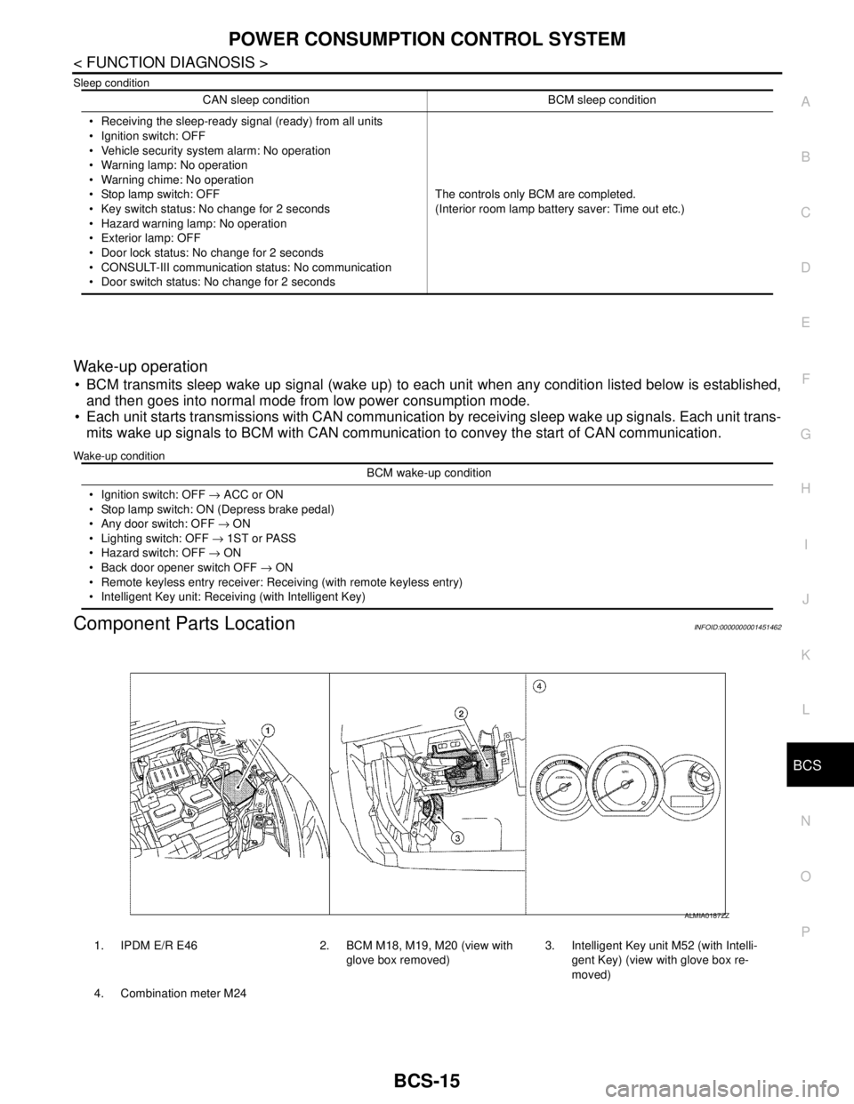
Component Parts LocationINFOID:0000000001451462
CAN sleep condition BCM sleep condition
Receiving the sleep-ready signal (ready) from all units
Ignition switch: OFF
Vehicle security system alarm: No operation
Warning lamp: No operation
Warning chime: No operation
Stop lamp switch: OFF
Key switch status: No change for 2 seconds
Hazard warning lamp: No operation
Exterior lamp: OFF
Door lock status: No change for 2 seconds
CONSULT-III communication status: No communication
Door switch status: No change for 2 secondsThe controls only BCM are completed.
(Interior room lamp battery saver: Time out etc.)
BCM wake-up condition
Ignition switch: OFF → ACC or ON
Stop lamp switch: ON (Depress brake pedal)
Any door switch: OFF → ON
Lighting switch: OFF → 1ST or PASS
Hazard switch: OFF → ON
Back door opener switch OFF → ON
Remote keyless entry receiver: Receiving (with remote keyless entry)
Intelligent Key unit: Receiving (with Intelligent Key)
1. IPDM E/R E46 2. BCM M18, M19, M20 (view with
glove box removed)3. Intelligent Key unit M52 (with Intelli-
gent Key) (view with glove box re-
moved)
4. Combination meter M24
ALMIA0187ZZ
Page 3002 of 5883

EXL-1
DRIVER CONTROLS
C
D
E
F
G
H
I
J
K
M
SECTION EXL
A
B
EXL
N
O
P
CONTENTS
EXTERIOR LIGHTING SYSTEM
BASIC INSPECTION ....................................5
DIAGNOSIS AND REPAIR WORKFLOW ..........5
Work Flow .................................................................5
FUNCTION DIAGNOSIS ...............................8
HEADLAMP (HALOGEN) ...................................8
System Diagram ........................................................8
System Description ...................................................8
Component Parts Location ........................................8
Component Description .............................................8
HEADLAMP (XENON) .......................................10
System Diagram ......................................................10
System Description .................................................10
Component Parts Location ......................................10
Component Description ..........................................11
AUTO LIGHT SYSTEM ......................................12
System Diagram ......................................................12
System Description .................................................12
Component Parts Location ......................................12
Component Description ...........................................13
HEADLAMP AIMING SYSTEM (MANUAL) .......14
System Diagram ......................................................14
System Description .................................................14
Component Parts Location ......................................14
Component Description ...........................................14
HEADLAMP AIMING SYSTEM (AUTOMAT-
IC) .......................................................................
15
System Diagram ......................................................15
System Description .................................................15
Component Parts Location ......................................15
Component Description ...........................................15
DAYTIME LIGHT SYSTEM ................................17
System Diagram ......................................................17
System Description .................................................17
Component Parts Location ......................................17
Component Description ..........................................18
FRONT FOG LAMP ..........................................19
System Diagram ......................................................19
System Description ..................................................19
Component Parts Location ......................................19
Component Description ...........................................20
REAR FOG LAMP .............................................21
System Diagram ......................................................21
System Description ..................................................21
Component Parts Location ......................................21
Component Description ..........................................21
TURN SIGNAL AND HAZARD WARNING
LAMPS ..............................................................
22
System Diagram ......................................................22
System Description ..................................................22
Component Parts Location ......................................22
Component Description ...........................................23
PARKING, LICENSE PLATE AND TAIL
LAMPS ..............................................................
24
System Diagram ......................................................24
System Description ..................................................24
Component Parts Location ......................................25
Component Description ...........................................25
DIAGNOSIS SYSTEM (BCM) ...........................26
COMMON ITEM .........................................................26
COMMON ITEM : CONSULT-III Function (BCM -
COMMON ITEM) .....................................................
26
BCM ...........................................................................26
BCM : CONSULT-III Function (BCM - BCM) ...........26
HEADLAMP ...............................................................26
HEADLAMP : CONSULT-III Function (BCM -
HEAD LAMP) ...........................................................
26
FLASHER ...................................................................27
Page 3004 of 5883

EXL-3
C
D
E
F
G
H
I
J
K
MA
B
EXL
N
O
P
TURN SIGNAL AND HAZARD WARNING
LAMPS ...............................................................
66
Wiring Diagram .......................................................66
PARKING, LICENSE PLATE AND TAIL
LAMPS ...............................................................
67
WITH DAYTIME LIGHT SYSTEM .............................67
WITH DAYTIME LIGHT SYSTEM : Wiring Dia-
gram ........................................................................
67
WITHOUT DAYTIME LIGHT SYSTEM ......................67
WITHOUT DAYTIME LIGHT SYSTEM : Wiring Di-
agram ......................................................................
68
STOP LAMP .......................................................69
Wiring Diagram .......................................................69
BACK-UP LAMP ................................................70
Wiring Diagram .......................................................70
ECU DIAGNOSIS .........................................71
BCM (BODY CONTROL MODULE) ...................71
Description ..............................................................71
IPDM E/R (INTELLIGENT POWER DISTRI-
BUTION MODULE ENGINE ROOM) .................
72
Description ..............................................................72
SYMPTOM DIAGNOSIS ..............................73
EXTERIOR LIGHTING SYSTEM SYMPTOMS ....73
Symptom Table .......................................................73
NORMAL OPERATING CONDITION .................75
Description ..............................................................75
BOTH SIDE HEADLAMPS DO NOT SWITCH
TO HIGH BEAM .................................................
76
Description ..............................................................76
Diagnosis Procedure ...............................................76
BOTH SIDE HEADLAMPS (LO) ARE NOT
TURNED ON .......................................................
77
Description ..............................................................77
Diagnosis Procedure ...............................................77
PARKING, LICENSE PLATE AND TAIL
LAMPS ARE NOT TURNED ON ........................
78
Description ..............................................................78
Diagnosis Procedure ...............................................78
BOTH SIDE FRONT FOG LAMPS ARE NOT
TURNED ON .......................................................
79
Description ..............................................................79
Diagnosis Procedure ...............................................79
PRECAUTION ..............................................80
PRECAUTIONS ..................................................80
Precaution for Supplemental Restraint System
(SRS) "AIR BAG" and "SEAT BELT PRE-TEN-
SIONER" .................................................................
80
ON-VEHICLE MAINTENANCE ....................81
HEADLAMP ......................................................81
Aiming Adjustment ...................................................81
FRONT FOG LAMP ..........................................83
Aiming Adjustment ...................................................83
ON-VEHICLE REPAIR .................................84
HEADLAMP ......................................................84
Bulb Replacement ...................................................84
Removal and Installation .........................................84
Disassembly and Assembly - Halogen ....................85
Disassembly and Assembly - Xenon .......................86
FRONT FOG LAMP ..........................................87
Bulb Replacement ...................................................87
Removal and Installation .........................................87
HEADLAMP AIMING CONTROL ......................88
Removal and Installation of Headlamp Aiming
Switch ......................................................................
88
Removal and Installation of Height Sensor .............89
AUTO LIGHT SYSTEM .....................................91
Removal and Installation of Light and Rain Sensor
....
91
SIDE TURN SIGNAL LAMP ..............................92
Bulb Replacement ...................................................92
Removal and Installation .........................................92
REAR COMBINATION LAMP ...........................93
Bulb Replacement ...................................................93
Removal and Installation .........................................93
Disassembly and Assembly .....................................93
HIGH-MOUNTED STOP LAMP ........................96
Bulb Replacement ...................................................96
Removal and Installation .........................................96
LICENSE PLATE LAMP ...................................98
Bulb Replacement ...................................................98
Removal and Installation .........................................98
REAR FOG LAMP ...........................................100
Bulb Replacement .................................................100
Removal and Installation .......................................100
LIGHTING & TURN SIGNAL SWITCH ...........101
Removal and Installation .......................................101
HAZARD SWITCH ..........................................102
Removal and Installation .......................................102
SERVICE DATA AND SPECIFICATIONS
(SDS) ..........................................................
103
Page 3013 of 5883
EXL-12
< FUNCTION DIAGNOSIS >
AUTO LIGHT SYSTEM
AUTO LIGHT SYSTEM
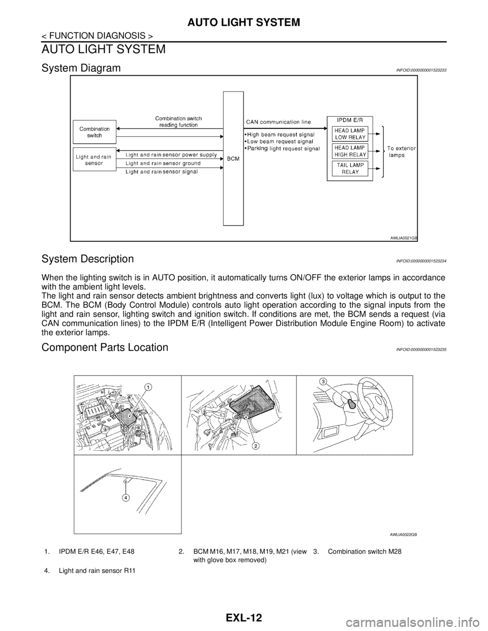
System DiagramINFOID:0000000001523233
System DescriptionINFOID:0000000001523234
When the lighting switch is in AUTO position, it automatically turns ON/OFF the exterior lamps in accordance
with the ambient light levels.
The light and rain sensor detects ambient brightness and converts light (lux) to voltage which is output to the
BCM. The BCM (Body Control Module) controls auto light operation according to the signal inputs from the
light and rain sensor, lighting switch and ignition switch. If conditions are met, the BCM sends a request (via
CAN communication lines) to the IPDM E/R (Intelligent Power Distribution Module Engine Room) to activate
the exterior lamps.
Component Parts LocationINFOID:0000000001523235
AWLIA0021GB
1. IPDM E/R E46, E47, E48 2. BCM M16, M17, M18, M19, M21 (view
with glove box removed)3. Combination switch M28
4. Light and rain sensor R11
AWLIA0022GB
Page 3074 of 5883
EXTERIOR LIGHTING SYSTEM SYMPTOMS
EXL-73
< SYMPTOM DIAGNOSIS >
C
D
E
F
G
H
I
J
K
MA
B
EXL
N
O
P
SYMPTOM DIAGNOSIS
EXTERIOR LIGHTING SYSTEM SYMPTOMS
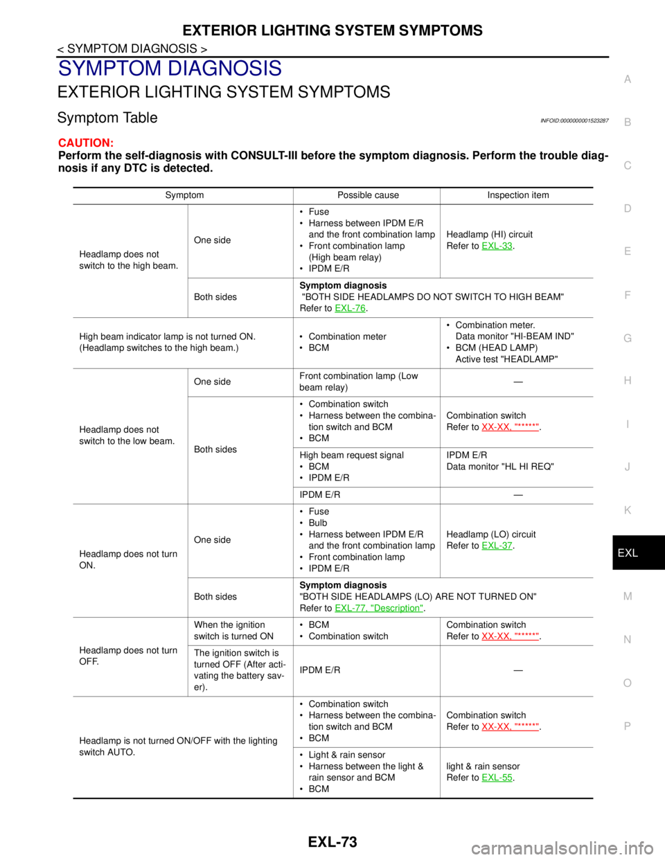
Symptom TableINFOID:0000000001523287
CAUTION:
Perform the self-diagnosis with CONSULT-III before the symptom diagnosis. Perform the trouble diag-
nosis if any DTC is detected.
Symptom Possible cause Inspection item
Headlamp does not
switch to the high beam.One sideFuse
Harness between IPDM E/R
and the front combination lamp
Front combination lamp
(High beam relay)
IPDM E/RHeadlamp (HI) circuit
Refer to EXL-33
.
Both sidesSymptom diagnosis
"BOTH SIDE HEADLAMPS DO NOT SWITCH TO HIGH BEAM"
Refer to EXL-76
.
High beam indicator lamp is not turned ON.
(Headlamp switches to the high beam.) Combination meter
BCM Combination meter.
Data monitor "HI-BEAM IND"
BCM (HEAD LAMP)
Active test "HEADLAMP"
Headlamp does not
switch to the low beam.One sideFront combination lamp (Low
beam relay)—
Both sides Combination switch
Harness between the combina-
tion switch and BCM
BCMCombination switch
Refer to XX-XX, "*****"
.
High beam request signal
BCM
IPDM E/RIPDM E/R
Data monitor "HL HI REQ"
IPDM E/R —
Headlamp does not turn
ON.One sideFuse
Bulb
Harness between IPDM E/R
and the front combination lamp
Front combination lamp
IPDM E/RHeadlamp (LO) circuit
Refer to EXL-37
.
Both sidesSymptom diagnosis
"BOTH SIDE HEADLAMPS (LO) ARE NOT TURNED ON"
Refer to EXL-77, "
Description".
Headlamp does not turn
OFF.When the ignition
switch is turned ONBCM
Combination switchCombination switch
Refer to XX-XX, "*****"
.
The ignition switch is
turned OFF (After acti-
vating the battery sav-
er).IPDM E/R —
Headlamp is not turned ON/OFF with the lighting
switch AUTO. Combination switch
Harness between the combina-
tion switch and BCM
BCMCombination switch
Refer to XX-XX, "*****"
.
Light & rain sensor
Harness between the light &
rain sensor and BCM
BCMlight & rain sensor
Refer to EXL-55
.
Page 3075 of 5883
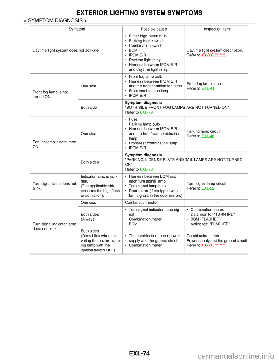
EXL-74
< SYMPTOM DIAGNOSIS >
EXTERIOR LIGHTING SYSTEM SYMPTOMS
Daytime light system does not activate. Either high beam bulb
Parking brake switch
Combination switch
BCM
IPDM E/R
Daytime light relay
Harness between IPDM E/R
and daytime light relay.Daytime light system description.
Refer to XX-XX, "*****"
.
Front fog lamp is not
turned ON.One side Front fog lamp bulb
Harness between IPDM E/R
and the front combination lamp
Front combination lamp
IPDM E/RFront fog lamp circuit
Refer to EXL-41
.
Both sideSymptom diagnosis
"BOTH SIDE FRONT FOG LAMPS ARE NOT TURNED ON"
Refer to EXL-79
.
Parking lamp is not turned
ON.One sideFuse
Parking lamp bulb
Harness between IPDM E/R
and the front/rear combination
lamp
Front/rear combination lamp
IPDM E/RParking lamp circuit
Refer to EXL-46
.
Both sidesSymptom diagnosis
"PARKING, LICENSE PLATE AND TAIL LAMPS ARE NOT TURNED
ON"
Refer to EXL-78
.
Turn signal lamp does not
blink.Indicator lamp is nor-
mal.
(The applicable side
performs the high flash-
er activation). Harness between BCM and
each turn signal lamp
Turn signal lamp bulb
Door mirror (if equipped with
turn signals in the door mirrors)Turn signal lamp circuit
Refer to EXL-52
.
Turn signal indicator lamp
does not blink.One side Combination meter —
Both sides
(Always) Turn signal indicator lamp sig-
nal
Combination meter
BCM Combination meter.
Data monitor "TURN IND"
BCM (FLASHER)
Active test "FLASHER"
Both sides
(Does blink when acti-
vating the hazard warn-
ing lamp with the
ignition switch OFF) The combination meter power
supply and the ground circuit
Combination meterCombination meter
Power supply and the ground circuit
Refer to XX-XX, "*****"
. Symptom Possible cause Inspection item
Page 4330 of 5883

MWI
DIAGNOSIS SYSTEM (METER)
MWI-23
< FUNCTION DIAGNOSIS >
C
D
E
F
G
H
I
J
K
L
MB A
O
P
NOTE:
Some items are not available due to vehicle specification.
*: The monitor will indicate “OFF” even though the brake warning lamp is on if either of the following conditions exist.
The parking brake is engaged
The brake fluid level is lowDOOR W/L [ON/OFF] X Displays [ON/OFF] condition of door warning lamp.
HI-BEAM IND [ON/OFF] X Displays [ON/OFF] condition of high beam indicator.
TURN IND [ON/OFF] X Displays [ON/OFF] condition of turn indicator.
FR FOG IND X Displays [ON/OFF] condition of front fog lamp indicator.
RR FOG IND X Displays [ON/OFF] condition of rear fog lamp indicator.
OIL W/L [ON/OFF] X Displays [ON/OFF] condition of oil pressure warning lamp.
LIGHT IND X Displays [ON/OFF] condition of exterior lamp indicator.
VDC/TCS IND [ON/OFF] X Displays [ON/OFF] condition of VDC OFF indicator lamp.
ABS W/L [ON/OFF] X Displays [ON/OFF] condition of ABS warning lamp.
SLIP IND [ON/OFF] X Displays [ON/OFF] condition of SLIP indicator lamp.
BRAKE W/L [ON/OFF] X Displays [ON/OFF] condition of brake warning lamp.*
OIL LEVEL IND X Displays [ON/OFF] condition of oil level indicator.
KEY G W/L [ON/OFF] X Displays [ON/OFF] condition of key green warning lamp.
KEY R W/L [ON/OFF] X Displays [ON/OFF] condition of key red warning lamp.
KEY KNOB W/L [ON/OFF] X Displays [ON/OFF] condition of key knob warning lamp.
PNP P SW X X Displays [ON/OFF] condition of inhibitor P switch.
PNP N SW X X Displays [ON/OFF] condition of inhibitor N switch.
O/D OFF SW X Displays [ON/OFF] condition of O/D OFF switch.
BRAKE SW [ON/OFF] X Displays [ON/OFF] condition of parking brake switch.
P RANGE IND [ON/OFF] X X Displays [ON/OFF] condition of A/T shift P range indicator.
R RANGE IND [ON/OFF] X X Displays [ON/OFF] condition of A/T shift R range indicator.
N RANGE IND [ON/OFF] X X Displays [ON/OFF] condition of A/T shift N range indicator.
D RANGE IND [ON/OFF] X X Displays [ON/OFF] condition of A/T shift D range indicator.
2 RANGE IND [ON/OFF] X X Displays [ON/OFF] condition of A/T shift 2 range indicator.
1 RANGE IND [ON/OFF] X X Displays [ON/OFF] condition of A/T shift 1range indicator.
O/D OFF W/L X Displays [ON/OFF] condition of O/D OFF indicator lamp.
CRUISE IND [ON/OFF] X Displays [ON/OFF] condition of CRUISE indicator.
EPS W/L X Displays [ON/OFF] condition of EPS warning lamp. Display item [Unit]MAIN
SIGNALSSELECTION
FROM MENUDescription
Page 5733 of 5883

WCS-18
< FUNCTION DIAGNOSIS >
DIAGNOSIS SYSTEM (METER)
DIAGNOSIS SYSTEM (METER)
CONSULT-III Function (METER/M&A)INFOID:0000000001728303
CONSULT-III can display each diagnostic item using the diagnostic test modes shown following.
SELF-DIAG RESULTS
Display Item List
Refer to MWI-54, "DTC Index".
DATA MONITOR
Display Item List
X: Applicable
METER/M&A diagnosis mode Description
SELF-DIAG RESULTS Displays combination meter self-diagnosis results.
DATA MONITOR Displays combination meter input/output data in real time.
CAN DIAG SUPPORT MNTR The result of transmit/receive diagnosis of CAN communication can be read.
Display item [Unit]MAIN
SIGNALSSELECTION
FROM MENUDescription
SPEED METER [km/h] or [mph] X X Displays the value of vehicle speed signal.
SPEED OUTPUT [km/h] or [mph] X XDisplays the value of vehicle speed signal, which is transmitted to
each unit with CAN communication.
TACHO METER [rpm] X X Displays the value of engine speed signal, which is input from ECM.
W TEMP METER [°C] or [°F] X XDisplays the value of engine coolant temperature signal, which is in-
put from ECM.
FUEL METER [lit.] X XDisplays the value, which processes a resistance signal from fuel
gauge.
DISTANCE [km] or [mile] X XDisplays the value, which is calculated by vehicle speed signal, fuel
gauge and fuel consumption from ECM.
FUEL W/L [ON/OFF] X X Displays [ON/OFF] condition of low-fuel warning lamp.
C-ENG W/L [ON/OFF] X Displays [ON/OFF] condition of malfunction indicator lamp.
SEAT BELT W/L [ON/OFF] X Indicates [ON/OFF] condition of seat belt warning lamp.
BUZZER [ON/OFF] X X Displays [ON/OFF] condition of buzzer.
DOOR W/L [ON/OFF] X Displays [ON/OFF] condition of door warning lamp.
HI-BEAM IND [ON/OFF] X Displays [ON/OFF] condition of high beam indicator.
TURN IND [ON/OFF] X Displays [ON/OFF] condition of turn indicator.
FR FOG IND X Displays [ON/OFF] condition of front fog lamp indicator.
RR FOG IND X Displays [ON/OFF] condition of rear fog lamp indicator.
OIL W/L [ON/OFF] X Displays [ON/OFF] condition of oil pressure warning lamp.
LIGHT IND X Displays [ON/OFF] condition of exterior lamp indicator.
VDC/TCS IND [ON/OFF] X Displays [ON/OFF] condition of VDC OFF indicator lamp.
ABS W/L [ON/OFF] X Displays [ON/OFF] condition of ABS warning lamp.
SLIP IND [ON/OFF] X Displays [ON/OFF] condition of SLIP indicator lamp.
BRAKE W/L [ON/OFF] X Displays [ON/OFF] condition of brake warning lamp.*
OIL LEVEL IND X Displays [ON/OFF] condition of oil level indicator.
KEY G W/L [ON/OFF] X Displays [ON/OFF] condition of key green warning lamp.
KEY R W/L [ON/OFF] X Displays [ON/OFF] condition of key red warning lamp.
KEY KNOB W/L [ON/OFF] X Displays [ON/OFF] condition of key knob warning lamp.
PNP P SW X X Displays [ON/OFF] condition of inhibitor P switch.