light and rain sensor NISSAN TIIDA 2007 Service Repair Manual
[x] Cancel search | Manufacturer: NISSAN, Model Year: 2007, Model line: TIIDA, Model: NISSAN TIIDA 2007Pages: 5883, PDF Size: 78.95 MB
Page 139 of 5883

BCS-4
< BASIC INSPECTION >
INSPECTION AND ADJUSTMENT
When replacing BCM, you must perform WRITE CONFIGURATION with CONSULT-III.
Complete the procedure of WRITE CONFIGURATION in order.
If you set incorrect WRITE CONFIGURATION, incidents will occur.
Configuration is different for each vehicle model. Confirm configuration of each vehicle model.
CONFIGURATION : Special Repair RequirementINFOID:0000000001451452
1. WRITING VEHICLE SPECIFICATION
Perform “WRITE CONFIGURATION” with CONSULT-III.
When writing saved data>>GO TO 2
When writing manually>>GO TO 3
2. PERFORM “WRITE CONFIGURATION - CONFIG FILE”
Perform “WRITE CONFIGURATION - Config file” with CONSULT-III.
>> WORK END
3. PERFORM “WRITE CONFIGURATION - MANUAL SELECTION”
For “WRITE CONFIGURATION - Manual selection”, using the following flow chart, identify the correct model
and configuration list.
Confirm and/or change setting value for each item according to the configuration list.
Depending on CONSULT-III software version being used, some or all of the write configuration items shown in
the following configuration lists may be displayed. If an item does not display on the CONSULT-III “WRITE
CONFIGURATION - Manual selection” screen, then it is an auto setting item and it cannot be manually set or
changed.
Gasoline engine models (RHD)
Gasoline engine models (LHD)
MANUAL SETTING ITEM
Items Setting value
HANDLE RHD
PTC HEATER WITHOUT
AUTO LIGHT WITH⇔WITHOUT
KEYLESS ENTRY WITH⇔WITHOUT
DTRL WITHOUT
THEFT ALARM WITH⇔WITHOUT
AUTO SETTING ITEM
RAIN SENSOR WITH or WITHOUT
H/L WSR SWTRG FR WSR SW
H/L_BULB H4 HALOGEN or DEFAULT
FR FOG LAMP WITH or WITHOUT
DONGLE WITH or WITHOUT
SUPER LOCK WITH
I-KEY WITH or WITHOUT
DOOR/L SPEED WITH
H/L BAT SAVER WITH
KEY WARNING MODE1
R LAMP LOGIC MODE2
Page 140 of 5883

BCS
INSPECTION AND ADJUSTMENT
BCS-5
< BASIC INSPECTION >
C
D
E
F
G
H
I
J
K
L B A
O
P N
Diesel engine models (RHD)
Diesel engine models (LHD)
MANUAL SETTING ITEM
Items Setting value
HANDLE LHD
PTC HEATER WITHOUT
AUTO LIGHT WITH⇔WITHOUT
KEYLESS ENTRY WITH⇔WITHOUT
DTRL WITH⇔WITHOUT
THEFT ALARM WITHOUT
AUTO SETTING ITEM
RAIN SENSOR WITH or WITHOUT
H/L WSR SWTRG FR WSR SW
H/L_BULB H4 HALOGEN or DEFAULT
FR FOG LAMP WITH or WITHOUT
DONGLE WITH or WITHOUT
SUPER LOCK WITHOUT
I-KEY WITH or WITHOUT
DOOR/L SPEED WITH
H/L BAT SAVER WITH
KEY WARNING MODE1
R LAMP LOGIC MODE2
MANUAL SETTING ITEM
Items Setting value
HANDLE RHD
PTC HEATER WITHOUT
AUTO LIGHT WITH⇔WITHOUT
KEYLESS ENTRY WITH⇔WITHOUT
DTRL WITHOUT
THEFT ALARM WITH⇔WITHOUT
AUTO SETTING ITEM
RAIN SENSOR WITH or WITHOUT
H/L WSR SWTRG FR WSR SW
H/L_BULB H4 HALOGEN or DEFAULT
FR FOG LAMP WITH or WITHOUT
DONGLE WITH or WITHOUT
SUPER LOCK WITH
I-KEY WITH or WITHOUT
DOOR/L SPEED WITH
H/L BAT SAVER WITH
KEY WARNING MODE1
R LAMP LOGIC MODE2
Page 141 of 5883

BCS-6
< BASIC INSPECTION >
INSPECTION AND ADJUSTMENT
>> WORK END
MANUAL SETTING ITEM
Items Setting value
HANDLE LHD
PTC HEATER 2 PTC
AUTO LIGHT WITH⇔WITHOUT
KEYLESS ENTRY WITH⇔WITHOUT
DTRL WITH⇔WITHOUT
THEFT ALARM WITHOUT
AUTO SETTING ITEM
RAIN SENSOR WITH or WITHOUT
H/L WSR SWTRG FR WSR SW
H/L_BULB H4 HALOGEN or DEFAULT
FR FOG LAMP WITH or WITHOUT
DONGLE WITH or WITHOUT
SUPER LOCK WITHOUT
I-KEY WITH or WITHOUT
DOOR/L SPEED WITH
H/L BAT SAVER WITH
KEY WARNING MODE1
R LAMP LOGIC MODE2
Page 156 of 5883

BCS
DIAGNOSIS SYSTEM (BCM)
BCS-21
< FUNCTION DIAGNOSIS >
C
D
E
F
G
H
I
J
K
L B A
O
P N
ACTIVE TEST
WIPER
WIPER : CONSULT-III Function (BCM - WIPER)INFOID:0000000001451471
WORK SUPPORT
HI BEAM SW [ON/OFF]
Each switch status that BCM judges from the combination switch reading function H/L SW POS [ON/OFF]
LIGHT SW 1ST [ON/OFF]
PASSING SW [ON/OFF]
AUTO LIGHT SW [ON/OFF]
FR FOG SW [ON/OFF]
RR FOG SW [ON/OFF]
DOOR SW-DR [ON/OFF] The switch status input from front door switch (driver side)
ENGINE STATUS The engine status received from ECM with CAN communication
LIT-SEN FAIL [OK/NOTOK] The sensor status received from light & rain sensor with serial link
The serial link condition that BCM judges
AUT LIGHT SYS [ON/OFF] Auto light system status that BCM judges from the vehicle conditionMonitor item
[Unit]Description
Test item Operation Description
TAIL LAMPONTransmits the position light request signal to IPDM E/R with CAN com-
munication to turn the tail lamp ON.
OFF Stops the tail lamp request signal transmission.
HEAD LAMPHITransmits the high beam request signal with CAN communication to turn
the headlamp (HI).
LOTransmits the low beam request signal with CAN communication to turn
the headlamp (LO).
OFF Stops the high & low beam request signal transmission.
FR FOG LAMPONTransmits the front fog lights request signal to IPDM E/R with CAN com-
munication to turn the front fog lamp ON.
OFF Stops the front fog lights request signal transmission.
RR FOG LAMPON Outputs the voltage to turn the rear fog lamp ON.
Transmits the rear fog lamp status signal to the combination meter with
CAN communication to turn the rear fog lamp indicator lamp ON.
OFF Stops the voltage to turn the rear fog lamp OFF.
Stops the rear fog lamp status signal transmission.
DAYTIME RUNNING LIGHTONTransmits the day time running light request signal to IPDM E/R with
CAN communication to turn the each lamps ON.
OFF Stops the day time running light request signal transmission.
Work ItemSetting
ItemDescription
WIPER SPEED
SETTINGON
1With vehicle speed
(Front wiper intermittent time linked with the vehicle speed and wiper intermittent dial position)
OFFWithout vehicle speed
(Front wiper intermittent time linked with the wiper intermittent dial position)
RR WIP RVRS
SETON
2Change ON/OFF mode setting or rear wiper operation when gear is shifted to reverse
OFF
Page 172 of 5883

BCS
BCM (BODY CONTROL MODULE)
BCS-37
< ECU DIAGNOSIS >
C
D
E
F
G
H
I
J
K
L B A
O
P N
I-KEY UNLOCK1UNLOCK button of Intelligent Key is not pressed OFF
UNLOCK button of Intelligent Key is pressed ON
KEY SW
2Mechanical key is removed from key cylinder OFF
Mechanical key is inserted to key cylinder ON
KEYLESS LOCK
2LOCK button of key fob is not pressed OFF
LOCK button of key fob is pressed ON
KEYLESS UNLOCK
2UNLOCK button of key fob is not pressed OFF
UNLOCK button of key fob is pressed ON
LIT-SEN FAILLight & rain sensor is in normal condition OK
Light & rain sensor is with internal error NOTOK
OIL PRESS SW Ignition switch OFF or ACC
Engine runningOFF
Ignition switch ON ON
OUT SIDE TEMP
NOTE:
Diesel engine modelsIgnition switch ONApproximately the same as outside
air temperature
PASSING SWOther than lighting switch PASS OFF
Lighting switch PASS ON
PUSH SW
1Return to ignition switch to LOCK position OFF
Press ignition switch ON
REAR DEF SWRear window defogger switch OFF OFF
Rear window defogger switch ON ON
RKE LOCK AND
UNLOCK
2NOTE:
The item is indicated, but not monitoredOFF
ON
RR FOG SWRear fog lamp switch OFF OFF
Rear fog lamp switch ON ON
RR WASHER SW
3Rear washer switch OFF OFF
Rear washer switch ON ON
RR WIPER INT
3Rear wiper switch OFF OFF
Rear wiper switch INT ON
RR WIPER ON
3 Rear wiper switch OFF OFF
Rear wiper switch ON ON
RR WIPER STOP
3Rear wiper stop position OFF
Other than rear wiper stop position ON
TAIL LAMP SWLighting switch OFF OFF
Lighting switch 1ST ON
TRNK OPNR SWWhen back door opener switch is not pressed OFF
When back door opener switch is pressed ON
TURN SIGNAL LTurn signal switch OFF OFF
Turn signal switch LH ON
TURN SIGNAL RTurn signal switch OFF OFF
Turn signal switch RH ON
UNLOCK WITH DRNOTE:
The item is indicated, but not monitoredOFF
ON
VEHICLE SPEED While driving Equivalent to speedometer reading Monitor Item Condition Value/Status
Page 183 of 5883
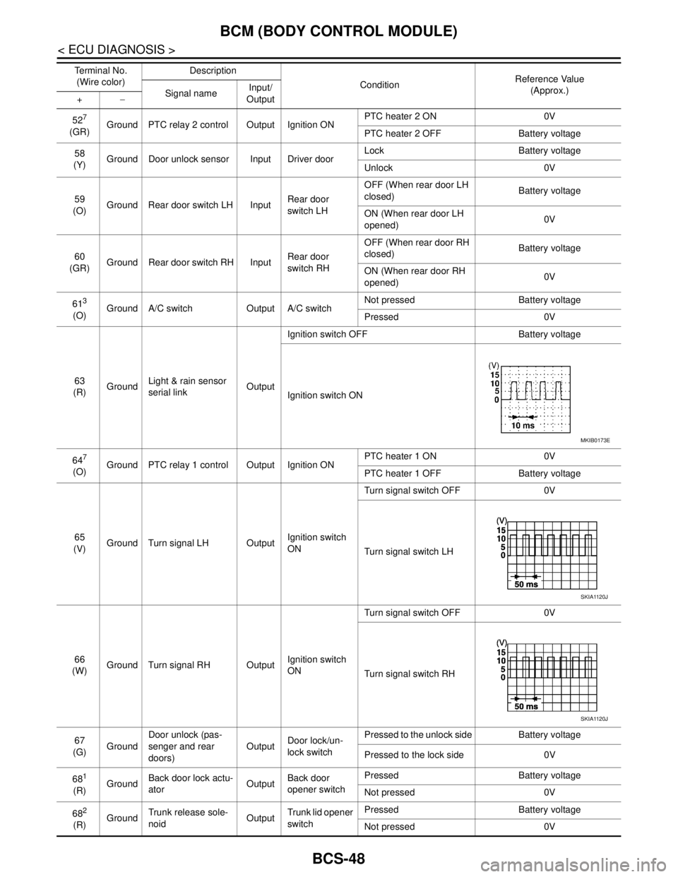
BCS-48
< ECU DIAGNOSIS >
BCM (BODY CONTROL MODULE)
527
(GR)Ground PTC relay 2 control Output Ignition ONPTC heater 2 ON 0V
PTC heater 2 OFF Battery voltage
58
(Y)Ground Door unlock sensor Input Driver doorLock Battery voltage
Unlock 0V
59
(O)Ground Rear door switch LH InputRear door
switch LHOFF (When rear door LH
closed) Battery voltage
ON (When rear door LH
opened)0V
60
(GR)Ground Rear door switch RH InputRear door
switch RHOFF (When rear door RH
closed) Battery voltage
ON (When rear door RH
opened)0V
61
3
(O)Ground A/C switch Output A/C switchNot pressed Battery voltage
Pressed 0V
63
(R)GroundLight & rain sensor
serial linkOutputIgnition switch OFF Battery voltage
Ignition switch ON
64
7
(O)Ground PTC relay 1 control Output Ignition ONPTC heater 1 ON 0V
PTC heater 1 OFF Battery voltage
65
(V)Ground Turn signal LH OutputIgnition switch
ONTurn signal switch OFF 0V
Turn signal switch LH
66
(W)Ground Turn signal RH OutputIgnition switch
ONTurn signal switch OFF 0V
Turn signal switch RH
67
(G)GroundDoor unlock (pas-
senger and rear
doors)OutputDoor lock/un-
lock switchPressed to the unlock side Battery voltage
Pressed to the lock side 0V
68
1
(R)GroundBack door lock actu-
atorOutputBack door
opener switchPressed Battery voltage
Not pressed 0V
68
2
(R)GroundTrunk release sole-
noidOutputTrunk lid opener
switchPressed Battery voltage
Not pressed 0V Te r m i n a l N o .
(Wire color)Description
ConditionReference Value
(Approx.)
Signal nameInput/
Output +−
MKIB0173E
SKIA1120J
SKIA1120J
Page 778 of 5883
![NISSAN TIIDA 2007 Service Repair Manual BCM (BODY CONTROL MODULE)
DLK-189
< ECU DIAGNOSIS >[WITH I-KEY, WITHOUT SUPER LOCK]
C
D
E
F
G
H
I
J
L
MA
B
DLK
N
O
P
TURN SIGNAL LAMP CONTROL
BCM detects the turn signal lamp circuit status from the t](/img/5/57395/w960_57395-777.png "NISSAN TIIDA 2007 Service Repair Manual BCM (BODY CONTROL MODULE)
DLK-189
< ECU DIAGNOSIS >[WITH I-KEY, WITHOUT SUPER LOCK]
C
D
E
F
G
H
I
J
L
MA
B
DLK
N
O
P
TURN SIGNAL LAMP CONTROL
BCM detects the turn signal lamp circuit status from the t")
BCM (BODY CONTROL MODULE)
DLK-189
< ECU DIAGNOSIS >[WITH I-KEY, WITHOUT SUPER LOCK]
C
D
E
F
G
H
I
J
L
MA
B
DLK
N
O
P
TURN SIGNAL LAMP CONTROL
BCM detects the turn signal lamp circuit status from the terminal voltage.
BCM increases the turn signal lamp blinking speed if the bulb or harness open is detected with the turn signal
lamp operating.
NOTE:
The blinking speed is normal while activating the hazard warning lamp.
LIGHT & RAIN SENSOR MALFUNCTION DETECTION FUNCTION
BCM controls the following items when LIGHT & RAIN sensor has a malfunction.
Auto Light Control
Headlamp is turned ON.
Front Wiper Control
The condition just before the activation of Fail-safe is maintained until the front wiper switch is turned OFF.
DTC Inspection Priority ChartINFOID:0000000001396648
DTC IndexINFOID:0000000001396649
NOTE:
Details of time display
CRNT: Displays when there is a malfunction now or after returning to the normal condition until turning igni-
tion switch OFF → ON again.
PAST: Displays when there is a malfunction that is detected in the past and stored.
1 - 39: Displayed if any previous malfunction is present when current condition is normal. It increases like 1
→ 2 → 3...38 → 39 after returning to the normal condition whenever ignition switch OFF → ON. The counter
remains at 39 even if the number of cycles exceeds it. It is counted from 1 again when turning ignition switch
OFF → ON after returning to the normal condition if the malfunction is detected again.
Display contents of CONSULT Fail-safe Cancellation
B2190: NATS ANTENNA AMP Inhibits engine cranking
Inhibits steering lock unlocking (Intelligent Key unit)
Fuel cut (ECM)Erase DTC
B2191: DIFFERENCE OF KEY Inhibits engine cranking
Inhibits steering lock unlocking (Intelligent Key unit)
Fuel cut (ECM)Erase DTC
B2192: ID DISCORD BCM-ECM Fuel cut (ECM) Erase DTC
B2193: CHAIN OF BCM-ECM Fuel cut (ECM) Erase DTC
B2194: DISCORD BCM-I-KEY Inhibits engine cranking
Inhibits steering lock unlocking (Intelligent Key unit)
Fuel cut (ECM)Erase DTC
B2195: ANTI SCANNING Inhibits engine cranking
Inhibits steering lock unlocking (Intelligent Key unit)
Fuel cut (ECM)Erase DTC
B2196: DONGLE NG Inhibits engine cranking
Inhibits steering lock unlocking (Intelligent Key unit)
Fuel cut (ECM)Erase DTC
Priority DTC
1 U1000: CAN COMM CIRCUIT
U1010: CONTROL UNIT (CAN)
2 B2190: NATS ANTENNA AMP
B2191: DIFFERNCE OF KEY
B2192: ID DISCORD BCM-ECM
B2193: CHAIN OF BCM-ECM
B2194: DISCORD BCM-I-KEY
B2195: ANTI SCANNING
B2196: DONGLE NG
Page 1007 of 5883
![NISSAN TIIDA 2007 Service Repair Manual DLK-418
< ECU DIAGNOSIS >[WITH I-KEY & SUPER LOCK]
BCM (BODY CONTROL MODULE)
TURN SIGNAL LAMP CONTROL
BCM detects the turn signal lamp circuit status from the terminal voltage.
BCM increases the turn](/img/5/57395/w960_57395-1006.png "NISSAN TIIDA 2007 Service Repair Manual DLK-418
< ECU DIAGNOSIS >[WITH I-KEY & SUPER LOCK]
BCM (BODY CONTROL MODULE)
TURN SIGNAL LAMP CONTROL
BCM detects the turn signal lamp circuit status from the terminal voltage.
BCM increases the turn")
DLK-418
< ECU DIAGNOSIS >[WITH I-KEY & SUPER LOCK]
BCM (BODY CONTROL MODULE)
TURN SIGNAL LAMP CONTROL
BCM detects the turn signal lamp circuit status from the terminal voltage.
BCM increases the turn signal lamp blinking speed if the bulb or harness open is detected with the turn signal
lamp operating.
NOTE:
The blinking speed is normal while activating the hazard warning lamp.
LIGHT & RAIN SENSOR MALFUNCTION DETECTION FUNCTION
BCM controls the following items when LIGHT & RAIN sensor has a malfunction.
Auto Light Control
Headlamp is turned ON.
Front Wiper Control
The condition just before the activation of Fail-safe is maintained until the front wiper switch is turned OFF.
DTC Inspection Priority ChartINFOID:0000000001530554
DTC IndexINFOID:0000000001530555
NOTE:
Details of time display
CRNT: Displays when there is a malfunction now or after returning to the normal condition until turning igni-
tion switch OFF → ON again.
PAST: Displays when there is a malfunction that is detected in the past and stored.
1 - 39: Displayed if any previous malfunction is present when current condition is normal. It increases like 1
→ 2 → 3...38 → 39 after returning to the normal condition whenever ignition switch OFF → ON. The counter
remains at 39 even if the number of cycles exceeds it. It is counted from 1 again when turning ignition switch
OFF → ON after returning to the normal condition if the malfunction is detected again.
Display contents of CONSULT Fail-safe Cancellation
B2190: NATS ANTENNA AMP Inhibits engine cranking
Inhibits steering lock unlocking (Intelligent Key unit)
Fuel cut (ECM)Erase DTC
B2191: DIFFERENCE OF KEY Inhibits engine cranking
Inhibits steering lock unlocking (Intelligent Key unit)
Fuel cut (ECM)Erase DTC
B2192: ID DISCORD BCM-ECM Fuel cut (ECM) Erase DTC
B2193: CHAIN OF BCM-ECM Fuel cut (ECM) Erase DTC
B2194: DISCORD BCM-I-KEY Inhibits engine cranking
Inhibits steering lock unlocking (Intelligent Key unit)
Fuel cut (ECM)Erase DTC
B2195: ANTI SCANNING Inhibits engine cranking
Inhibits steering lock unlocking (Intelligent Key unit)
Fuel cut (ECM)Erase DTC
B2196: DONGLE NG Inhibits engine cranking
Inhibits steering lock unlocking (Intelligent Key unit)
Fuel cut (ECM)Erase DTC
Priority DTC
1 U1000: CAN COMM CIRCUIT
U1010: CONTROL UNIT (CAN)
2 B2190: NATS ANTENNA AMP
B2191: DIFFERNCE OF KEY
B2192: ID DISCORD BCM-ECM
B2193: CHAIN OF BCM-ECM
B2194: DISCORD BCM-I-KEY
B2195: ANTI SCANNING
B2196: DONGLE NG
Page 2642 of 5883
![NISSAN TIIDA 2007 Service Repair Manual PRECAUTIONS
EC-1293
< PRECAUTION >[K9K]
C
D
E
F
G
H
I
J
K
L
MA
EC
N
P O
PRECAUTION
PRECAUTIONS
Precaution for Supplemental Restraint System (SRS) "AIR BAG" and "SEAT BELT
PRE-TENSIONER"
INFOID:000000](/img/5/57395/w960_57395-2641.png "NISSAN TIIDA 2007 Service Repair Manual PRECAUTIONS
EC-1293
< PRECAUTION >[K9K]
C
D
E
F
G
H
I
J
K
L
MA
EC
N
P O
PRECAUTION
PRECAUTIONS
Precaution for Supplemental Restraint System (SRS) \"AIR BAG\" and \"SEAT BELT
PRE-TENSIONER\"
INFOID:000000")
PRECAUTIONS
EC-1293
< PRECAUTION >[K9K]
C
D
E
F
G
H
I
J
K
L
MA
EC
N
P O
PRECAUTION
PRECAUTIONS
Precaution for Supplemental Restraint System (SRS) "AIR BAG" and "SEAT BELT
PRE-TENSIONER"
INFOID:0000000001706108
The Supplemental Restraint System such as “AIR BAG” and “SEAT BELT PRE-TENSIONER”, used along
with a front seat belt, helps to reduce the risk or severity of injury to the driver and front passenger for certain
types of collision. Information necessary to service the system safely is included in the SR and SB section of
this Service Manual.
WARNING:
To avoid rendering the SRS inoperative, which could increase the risk of personal injury or death in
the event of a collision which would result in air bag inflation, all maintenance must be performed by
an authorized NISSAN/INFINITI dealer.
Improper maintenance, including incorrect removal and installation of the SRS, can lead to personal
injury caused by unintentional activation of the system. For removal of Spiral Cable and Air Bag
Module, see the SR section.
Do not use electrical test equipment on any circuit related to the SRS unless instructed to in this
Service Manual. SRS wiring harnesses can be identified by yellow and/or orange harnesses or har-
ness connectors.
Precaution for Procedure without Cowl Top CoverINFOID:0000000001162744
When performing the procedure after removing cowl top cover, cover
the lower end of windshield with urethane, etc.
On Board Diagnostic (OBD) System of EngineINFOID:0000000001162745
The ECM has an on board diagnostic system. It will light up the malfunction indicator (MI) to warn the driver of
a malfunction causing emission deterioration.
CAUTION:
Be sure to turn the ignition switch OFF and disconnect the battery negative cable before any repair
or inspection work. The open/short circuit of related switches, sensors, solenoid valves, etc. will
cause the MI to light up.
Be sure to connect and lock the connectors securely after work. A loose (unlocked) connector will
cause the MI to light up due to the open circuit. (Be sure the connector is free from water, grease,
dirt, bent terminals, etc.)
Certain systems and components, especially those related to OBD, may use a new style slide-lock-
ing type harness connector. For description and how to disconnect, refer to XX-XX, "*****"
.
Be sure to route and secure the harnesses properly after work. The interference of the harness with
a bracket, etc. may cause the MI to light up due to the short circuit.
Be sure to connect rubber tubes properly after work. A misconnected or disconnected rubber tube
may cause the MI to light up due to the malfunction of the fuel system, etc.
Be sure to erase the unnecessary malfunction information (repairs completed) from the ECM before
returning the vehicle to the customer.
PIIB3706J
Page 3003 of 5883

EXL-2
FLASHER : CONSULT-III Function (BCM -
FLASHER) ..............................................................
27
COMB SW .................................................................28
COMB SW : CONSULT-III Function (BCM -
COMB SW) .............................................................
28
BATTERY SAVER ....................................................28
BATTERY SAVER : CONSULT-III Function (BCM
- BATTERY SAVER) ..............................................
28
DIAGNOSIS SYSTEM (IPDM E/R) ....................30
CONSULT - III Function (IPDM E/R) ......................30
DIAGNOSIS SYSTEM (HEADLAMP LEVEL-
IZER) ..................................................................
31
CONSULT-III Function ...........................................31
COMPONENT DIAGNOSIS ........................32
POWER SUPPLY AND GROUND CIRCUIT .....32
BCM (BODY CONTROL MODULE) .........................32
BCM (BODY CONTROL MODULE) : Diagnosis
Procedure ...............................................................
32
IPDM E/R (INTELLIGENT POWER DISTRIBU-
TION MODULE ENGINE ROOM) .............................
32
IPDM E/R (INTELLIGENT POWER DISTRIBU-
TION MODULE ENGINE ROOM) : Diagnosis Pro-
cedure .....................................................................
32
HEADLAMP (HI) CIRCUIT ................................33
HEADLAMP (HALOGEN) .........................................33
HEADLAMP (HALOGEN) : Description ..................33
HEADLAMP (HALOGEN) : Component Function
Check .....................................................................
33
HEADLAMP (HALOGEN) : Diagnosis Procedure ...33
HEADLAMP (XENON) ..............................................34
HEADLAMP (XENON) : Description .......................34
HEADLAMP (XENON) : Component Function
Check .....................................................................
34
HEADLAMP (XENON) : Diagnosis Procedure .......35
HEADLAMP (LO) CIRCUIT ...............................37
HEADLAMP (HALOGEN) .........................................37
HEADLAMP (HALOGEN) : Description ..................37
HEADLAMP (HALOGEN) : Component Function
Check .....................................................................
37
HEADLAMP (HALOGEN) : Diagnosis Procedure ...37
HEADLAMP (XENON) ..............................................38
HEADLAMP (XENON) : Description .......................38
HEADLAMP (XENON) : Component Function
Check .....................................................................
38
HEADLAMP (XENON) : Diagnosis Procedure .......39
FRONT FOG LAMP CIRCUIT ...........................41
Description ..............................................................41
Component Function Check ...................................41
Diagnosis Procedure ...............................................41
REAR FOG LAMP CIRCUIT .............................43
Description ..............................................................43
Component Function Check ...................................43
Diagnosis Procedure ...............................................43
PARKING LAMP CIRCUIT ................................46
WITH DAYTIME LIGHT SYSTEM .............................46
WITH DAYTIME LIGHT SYSTEM : Description .....46
WITH DAYTIME LIGHT SYSTEM : Component
Function Check .......................................................
46
WITH DAYTIME LIGHT SYSTEM : Diagnosis Pro-
cedure .....................................................................
46
WITHOUT DAYTIME LIGHT SYSTEM .....................48
WITHOUT DAYTIME LIGHT SYSTEM : Descrip-
tion ..........................................................................
48
WITHOUT DAYTIME LIGHT SYSTEM : Compo-
nent Function Check ...............................................
48
WITHOUT DAYTIME LIGHT SYSTEM : Diagno-
sis Procedure ..........................................................
49
TURN SIGNAL LAMP CIRCUIT ........................52
Description ..............................................................52
Component Function Check ...................................52
Diagnosis Procedure ...............................................52
LIGHT & RAIN SENSOR ...................................55
Description ..............................................................55
Component Function Check ...................................55
Diagnosis Procedure ...............................................55
HEADLAMP AIMER SWITCH ...........................57
Description ..............................................................57
Diagnosis Procedure ...............................................57
HEADLAMP (HALOGEN) .................................58
Wiring Diagram .......................................................58
HEADLAMP (XENON) .......................................59
Wiring Diagram .......................................................59
AUTO LIGHT SYSTEM .....................................60
Wiring Diagram .......................................................60
HEADLAMP AIMING SYSTEM (MANUAL) ......61
Wiring Diagram .......................................................61
HEADLAMP AIMING SYSTEM (AUTOMAT-
IC) ......................................................................
62
Wiring Diagram .......................................................62
DAYTIME LIGHT SYSTEM ...............................63
Wiring Diagram .......................................................63
FRONT FOG LAMP ...........................................64
Wiring Diagram .......................................................64
REAR FOG LAMP .............................................65
Wiring Diagram .......................................................65