NISSAN TIIDA 2008 Service Repair Manual
TIIDA 2008
NISSAN
NISSAN
https://www.carmanualsonline.info/img/5/57399/w960_57399-0.png
NISSAN TIIDA 2008 Service Repair Manual
Trending: Oil, clock, Supplemental Restraint System, MA-10, brake fluid, Engine mechanical, VIN
Page 2431 of 2771
PARKING BRAKE CONTROL
PB-5
< SERVICE INFORMATION >
C
D
E
G
H
I
J
K
L
MA
B
PB
N
O
P
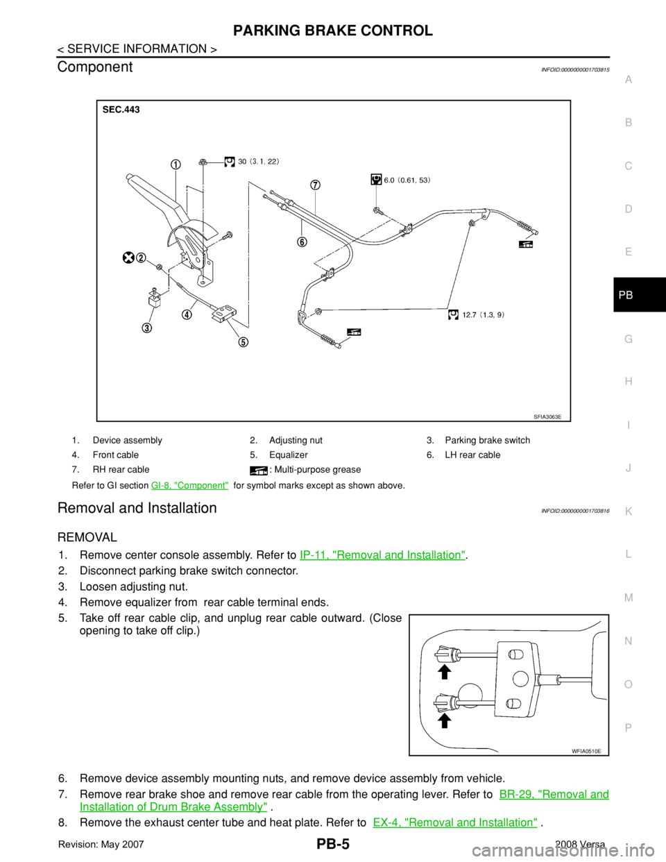
ComponentINFOID:0000000001703815
Removal and InstallationINFOID:0000000001703816
REMOVAL
1. Remove center console assembly. Refer to IP-11, "Removal and Installation".
2. Disconnect parking brake switch connector.
3. Loosen adjusting nut.
4. Remove equalizer from rear cable terminal ends.
5. Take off rear cable clip, and unplug rear cable outward. (Close
opening to take off clip.)
6. Remove device assembly mounting nuts, and remove device assembly from vehicle.
7. Remove rear brake shoe and remove rear cable from the operating lever. Refer to BR-29, "
Removal and
Installation of Drum Brake Assembly" .
8. Remove the exhaust center tube and heat plate. Refer to EX-4, "
Removal and Installation" .
1. Device assembly 2. Adjusting nut 3. Parking brake switch
4. Front cable 5. Equalizer 6. LH rear cable
7. RH rear cable : Multi-purpose grease
Refer to GI section GI-8, "
Component" for symbol marks except as shown above.
SFIA3063E
WFIA0510E
Page 2432 of 2771
PB-6
< SERVICE INFORMATION >
PARKING BRAKE CONTROL
9. Remove rear cable mounting bolt and nut, and then remove rear cable from the vehicle.
10. Remove adjusting nut and front cable from device assembly.
INSTALLATION
1. Installation is in the reverse order of the removal. Tighten mounting bolts and nuts to the specified torque.
2. Adjust clearance of rear brake shoes. Refer to PB-4, "
On-Vehicle Service" .
Page 2433 of 2771
SERVICE DATA AND SPECIFICATIONS (SDS)
PB-7
< SERVICE INFORMATION >
C
D
E
G
H
I
J
K
L
MA
B
PB
N
O
P
SERVICE DATA AND SPECIFICATIONS (SDS)
Parking Brake ControlINFOID:0000000001703817
Control typeHand lever
Number of notches [under a force of 196 N (20 kg-f, 44lb-f)] 8 −9
Number of notches when warning lamp switch comes on 1
Page 2434 of 2771

PG-1
ELECTRICAL
C
D
E
F
G
H
I
J
L
M
SECTION PG
A
B
PG
N
O
P
CONTENTS
POWER SUPPLY, GROUND & CIRCUIT ELEMENTS
SERVICE INFORMATION ............................2
PRECAUTIONS ...................................................2
Precaution for Supplemental Restraint System
(SRS) "AIR BAG" and "SEAT BELT PRE-TEN-
SIONER" ...................................................................
2
POWER SUPPLY ROUTING CIRCUIT ...............3
Schematic .................................................................3
Wiring Diagram - POWER - ......................................5
Fuse ........................................................................15
Fusible Link .............................................................15
Circuit Breaker (Built Into BCM) ..............................15
Circuit Breaker ........................................................15
IPDM E/R (INTELLIGENT POWER DISTRI-
BUTION MODULE ENGINE ROOM) .................
16
System Description .................................................16
CAN Communication System Description ...............17
Function of Detecting Ignition Relay Malfunction ....17
CONSULT-III Function (IPDM E/R) .........................17
Auto Active Test ......................................................19
IPDM E/R Terminal Arrangement ...........................22
Terminal and Reference Value for IPDM E/R .........23
IPDM E/R Power/Ground Circuit Inspection ...........25
Inspection with CONSULT-III (Self-Diagnosis) .......26
Removal and Installation of IPDM E/R ....................26
GROUND CIRCUIT ...........................................28
Ground Distribution ..................................................28
HARNESS .........................................................37
Harness Layout .......................................................37
Wiring Diagram Codes (Cell Codes) .......................58
ELECTRICAL UNITS LOCATION ....................61
Electrical Units Location ..........................................61
HARNESS CONNECTOR .................................65
Description ...............................................................65
ELECTRICAL UNITS ........................................68
Terminal Arrangement .............................................68
STANDARDIZED RELAY .................................69
Description ...............................................................69
SUPER MULTIPLE JUNCTION (SMJ) .............71
Terminal Arrangement .............................................71
FUSE BLOCK-JUNCTION BOX (J/B) ..............72
Terminal Arrangement .............................................72
FUSE AND FUSIBLE LINK BOX ......................73
Terminal Arrangement .............................................73
Page 2435 of 2771

PG-2
< SERVICE INFORMATION >
PRECAUTIONS
SERVICE INFORMATION
PRECAUTIONS
Precaution for Supplemental Restraint System (SRS) "AIR BAG" and "SEAT BELT
PRE-TENSIONER"
INFOID:0000000001704690
The Supplemental Restraint System such as “AIR BAG” and “SEAT BELT PRE-TENSIONER”, used along
with a front seat belt, helps to reduce the risk or severity of injury to the driver and front passenger for certain
types of collision. This system includes seat belt switch inputs and dual stage front air bag modules. The SRS
system uses the seat belt switches to determine the front air bag deployment, and may only deploy one front
air bag, depending on the severity of a collision and whether the front occupants are belted or unbelted.
Information necessary to service the system safely is included in the SRS and SB section of this Service Man-
ual.
WARNING:
• To avoid rendering the SRS inoperative, which could increase the risk of personal injury or death in
the event of a collision which would result in air bag inflation, all maintenance must be performed by
an authorized NISSAN/INFINITI dealer.
• Improper maintenance, including incorrect removal and installation of the SRS, can lead to personal
injury caused by unintentional activation of the system. For removal of Spiral Cable and Air Bag
Module, see the SRS section.
• Do not use electrical test equipment on any circuit related to the SRS unless instructed to in this
Service Manual. SRS wiring harnesses can be identified by yellow and/or orange harnesses or har-
ness connectors.
Page 2436 of 2771
POWER SUPPLY ROUTING CIRCUIT
PG-3
< SERVICE INFORMATION >
C
D
E
F
G
H
I
J
L
MA
B
PG
N
O
P
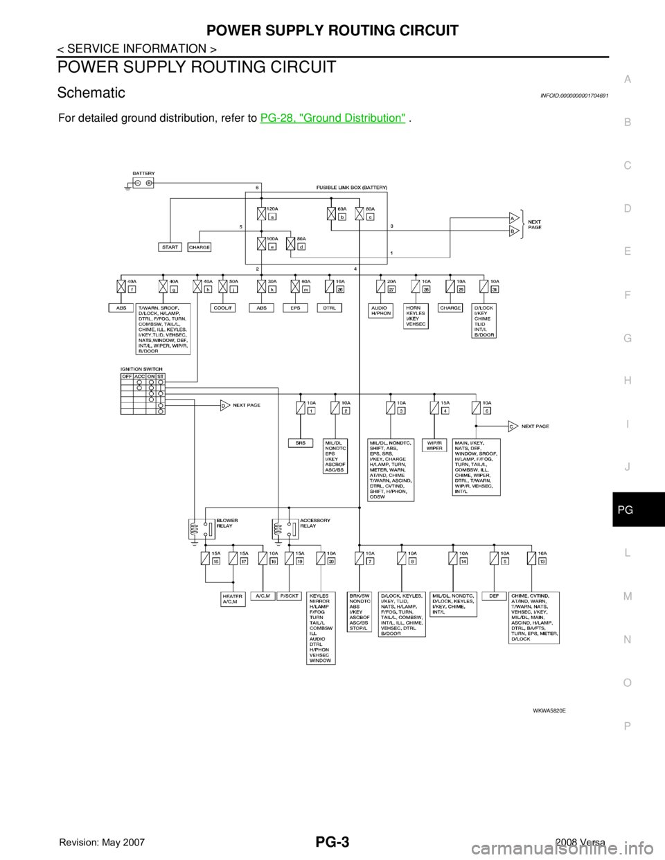
POWER SUPPLY ROUTING CIRCUIT
SchematicINFOID:0000000001704691
For detailed ground distribution, refer to PG-28, "Ground Distribution" .
WKWA5820E
Page 2437 of 2771
PG-4
< SERVICE INFORMATION >
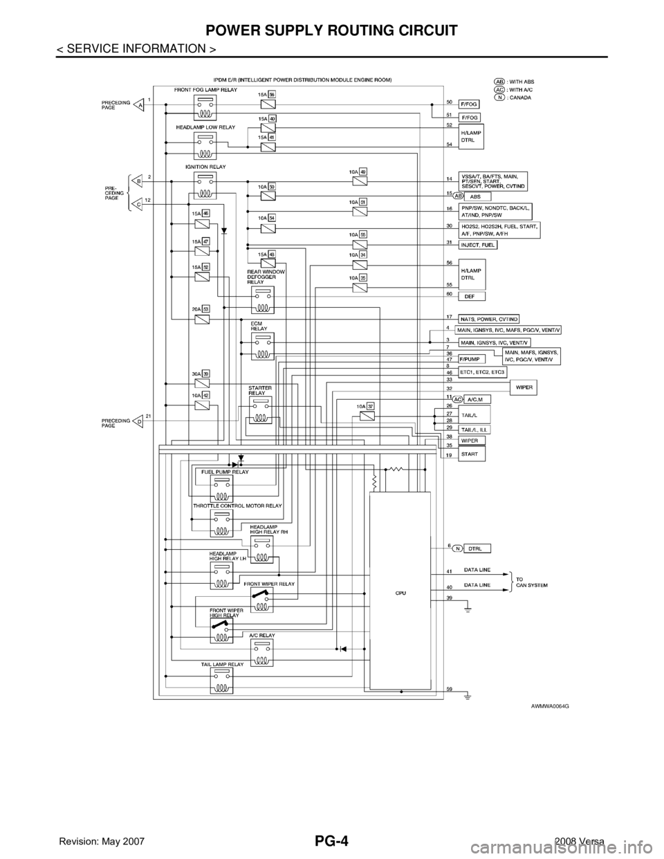
POWER SUPPLY ROUTING CIRCUIT
AWMWA0064G
Page 2438 of 2771
POWER SUPPLY ROUTING CIRCUIT
PG-5
< SERVICE INFORMATION >
C
D
E
F
G
H
I
J
L
MA
B
PG
N
O
P
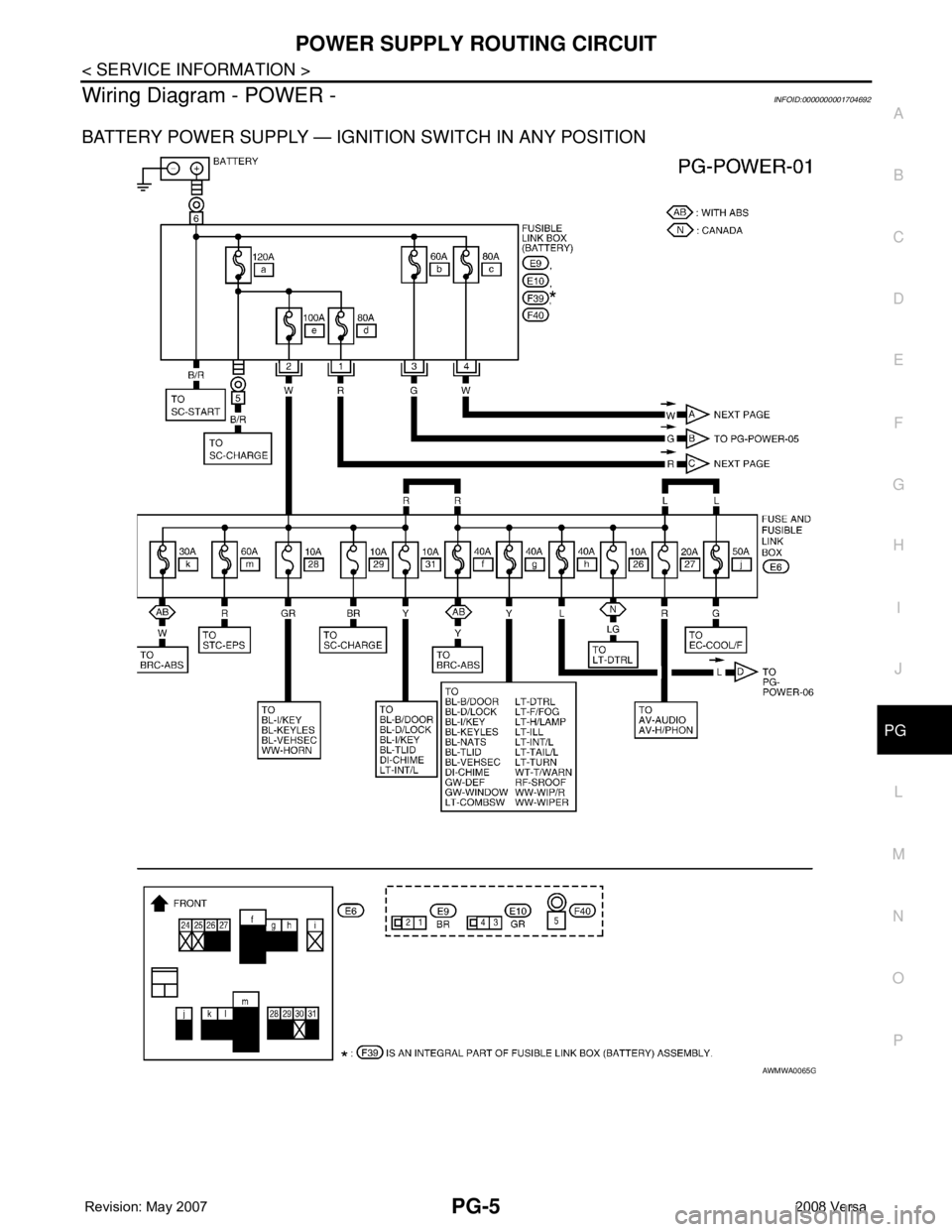
Wiring Diagram - POWER -INFOID:0000000001704692
BATTERY POWER SUPPLY — IGNITION SWITCH IN ANY POSITION
AWMWA0065G
Page 2439 of 2771
PG-6
< SERVICE INFORMATION >
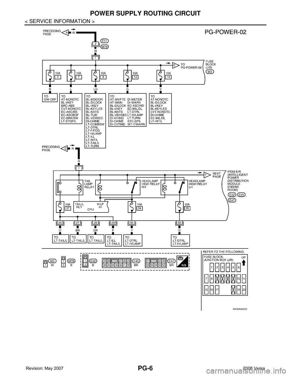
POWER SUPPLY ROUTING CIRCUIT
WKWA5822E
Page 2440 of 2771
POWER SUPPLY ROUTING CIRCUIT
PG-7
< SERVICE INFORMATION >
C
D
E
F
G
H
I
J
L
MA
B
PG
N
O
P
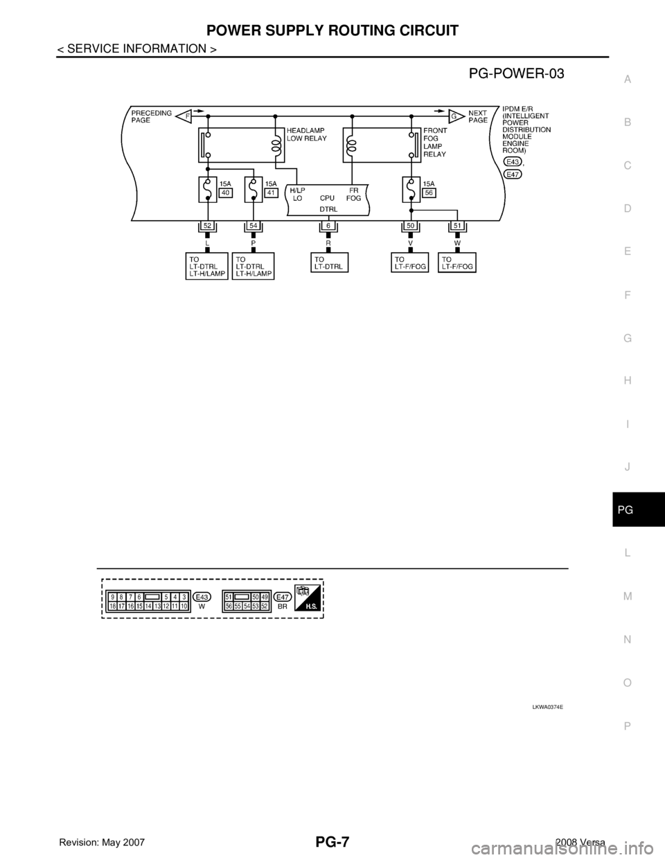
LKWA0374E
Trending: alternator, service interval reset, seats, maintenance schedule, flat tire, release, AUX


