NISSAN TIIDA 2008 Service Repair Manual
Manufacturer: NISSAN, Model Year: 2008, Model line: TIIDA, Model: NISSAN TIIDA 2008Pages: 2771, PDF Size: 60.61 MB
Page 731 of 2771
BODY REPAIR
BL-297
< SERVICE INFORMATION >
C
D
E
F
G
H
J
K
L
MA
B
BL
N
O
P
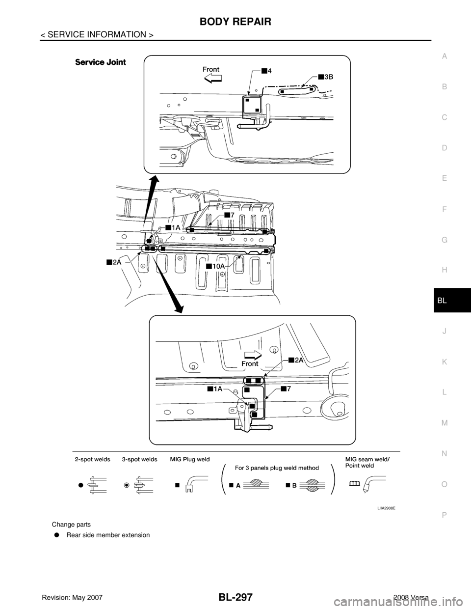
Change parts
●Rear side member extension
LIIA2908E
Page 732 of 2771

BR-1
BRAKES
C
D
E
G
H
I
J
K
L
M
SECTION BR
A
B
BR
N
O
P
CONTENTS
BRAKE SYSTEM
SERVICE INFORMATION ............................2
PRECAUTIONS ...................................................2
Precaution for Supplemental Restraint System
(SRS) "AIR BAG" and "SEAT BELT PRE-TEN-
SIONER" ...................................................................
2
Precaution for Brake System ....................................2
PREPARATION ...................................................3
Commercial Service Tool ..........................................3
NOISE, VIBRATION AND HARSHNESS
(NVH) TROUBLESHOOTING .............................
4
NVH Troubleshooting Chart ......................................4
BRAKE PEDAL ...................................................5
Inspection and Adjustment ........................................5
Removal and Installation ...........................................6
BRAKE FLUID .....................................................8
On Board Inspection .................................................8
Drain and Refill ..........................................................8
Bleeding Brake System .............................................8
BRAKE TUBE AND HOSE ................................10
Hydraulic Circuit ......................................................10
Front Brake Tube and Hose ....................................10
Rear Brake Tube and Hose ....................................11
Inspection After Installation .....................................11
BRAKE MASTER CYLINDER ............................13
On-Board Inspection ...............................................13
Removal and Installation .........................................13
Disassembly and Assembly ....................................13
BRAKE BOOSTER ...........................................18
On Board Inspection ................................................18
Removal and Installation .........................................18
VACUUM LINES ...............................................21
Component ..............................................................21
Removal and Installation .........................................21
Inspection ................................................................21
FRONT DISC BRAKE .......................................23
On Board Inspection ................................................23
Component ..............................................................23
Removal and Installation of Brake Pad ...................24
Removal and Installation of Brake Caliper Assem-
bly ............................................................................
25
Disassembly and Assembly of Brake Caliper As-
sembly .....................................................................
25
Brake Burnishing Procedure ....................................28
REAR DRUM BRAKE .......................................29
Component ..............................................................29
Removal and Installation of Drum Brake Assembly
....
29
Removal and Installation of Wheel Cylinder ............32
Disassembly and Assembly of Wheel Cylinder .......32
SERVICE DATA AND SPECIFICATIONS
(SDS) .................................................................
33
General Specification ..............................................33
Brake Pedal .............................................................33
Check Valve ............................................................33
Brake Booster ..........................................................33
Front Disc Brake ......................................................33
Rear Drum Brake .....................................................34
Page 733 of 2771

BR-2
< SERVICE INFORMATION >
PRECAUTIONS
SERVICE INFORMATION
PRECAUTIONS
Precaution for Supplemental Restraint System (SRS) "AIR BAG" and "SEAT BELT
PRE-TENSIONER"
INFOID:0000000001703775
The Supplemental Restraint System such as “AIR BAG” and “SEAT BELT PRE-TENSIONER”, used along
with a front seat belt, helps to reduce the risk or severity of injury to the driver and front passenger for certain
types of collision. This system includes seat belt switch inputs and dual stage front air bag modules. The SRS
system uses the seat belt switches to determine the front air bag deployment, and may only deploy one front
air bag, depending on the severity of a collision and whether the front occupants are belted or unbelted.
Information necessary to service the system safely is included in the SRS and SB section of this Service Man-
ual.
WARNING:
• To avoid rendering the SRS inoperative, which could increase the risk of personal injury or death in
the event of a collision which would result in air bag inflation, all maintenance must be performed by
an authorized NISSAN/INFINITI dealer.
• Improper maintenance, including incorrect removal and installation of the SRS, can lead to personal
injury caused by unintentional activation of the system. For removal of Spiral Cable and Air Bag
Module, see the SRS section.
• Do not use electrical test equipment on any circuit related to the SRS unless instructed to in this
Service Manual. SRS wiring harnesses can be identified by yellow and/or orange harnesses or har-
ness connectors.
Precaution for Brake SystemINFOID:0000000001703776
• Refill using recommended brake fluid. Refer to MA-10.
• Never reuse drained brake fluid.
• Be careful not to splash brake fluid on painted surface of body. If brake fluid is splashed on painted surfaces
of body immediately wipe it off with cloth and then wash it away with water.
• To clean or wash all parts of master cylinder, disc brake caliper and wheel cylinder, use new brake fluid.
• Never use mineral oils such as gasoline or kerosene. They will ruin rubber parts of the hydraulic system.
• Use a flare nut wrench when removing a brake tube and use a
flare nut torque wrench when installing a brake tube.
• When installing brake tubes and hoses, be sure to check torque.
• Before working, turn ignition switch OFF and disconnect connec-
tors of ABS actuator and electric unit (control unit) or the battery
cable from the negative terminal.
• Burnish the new braking surfaces after refinishing or replacing
drums or rotors, after replacing pads or linings, or if a soft pedal
occurs at very low mileage. Refer toBR-28, "
Brake Burnishing
Procedure" .
SBR686C
Page 734 of 2771
PREPARATION
BR-3
< SERVICE INFORMATION >
C
D
E
G
H
I
J
K
L
MA
B
BR
N
O
P
PREPARATION
Commercial Service ToolINFOID:0000000001703777
Tool nameDescription
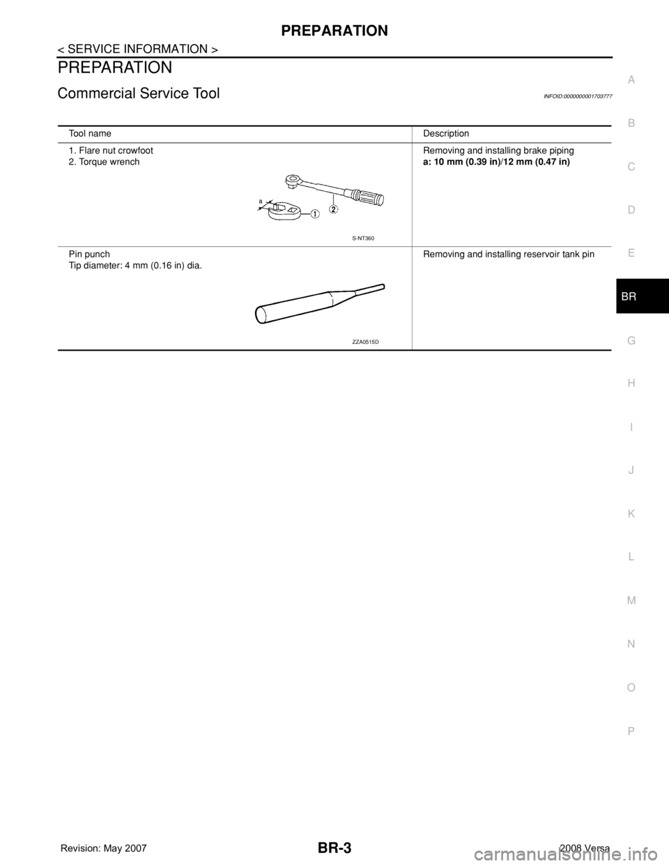
1. Flare nut crowfoot
2. Torque wrenchRemoving and installing brake piping
a: 10 mm (0.39 in)/12 mm (0.47 in)
Pin punch
Tip diameter: 4 mm (0.16 in) dia. Removing and installing reservoir tank pin
S-NT360
ZZA0515D
Page 735 of 2771
BR-4
< SERVICE INFORMATION >
NOISE, VIBRATION AND HARSHNESS (NVH) TROUBLESHOOTING
NOISE, VIBRATION AND HARSHNESS (NVH) TROUBLESHOOTING
NVH Troubleshooting ChartINFOID:0000000001703778
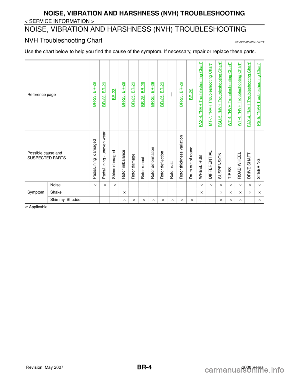
Use the chart below to help you find the cause of the symptom. If necessary, repair or replace these parts.
×: ApplicableReference page
BR-23
, BR-29
BR-23
, BR-29BR-23
BR-25
, BR-29
BR-25
, BR-29
BR-25
, BR-29
BR-25
, BR-29
BR-25
, BR-29—
BR-25, BR-29BR-29
FAX-4, "
NVH Troubleshooting Chart
"
MT-7, "
NVH Troubleshooting Chart
"
FSU-5, "
NVH Troubleshooting Chart
"
WT-4, "
NVH Troubleshooting Chart
"
WT-4, "
NVH Troubleshooting Chart
"
FAX-4, "
NVH Troubleshooting Chart
"
PS-5, "
NVH Troubleshooting Chart
"
Possible cause and
SUSPECTED PARTS
Pads/Lining damaged
Pads/Lining - uneven wear
Shims damaged
Rotor imbalance
Rotor damage
Rotor runout
Rotor deformation
Rotor deflection
Rotor rust
Rotor thickness variation
Drum out of round
WHEEL HUB
DIFFERENTIAL
SUSPENSION
TIRES
ROAD WHEEL
DRIVE SHAFT
STEERING
SymptomNoise××× ×××××××
Shake× × ×××××
Shimmy, Shudder×××××××× ××× ×
Page 736 of 2771
BRAKE PEDAL
BR-5
< SERVICE INFORMATION >
C
D
E
G
H
I
J
K
L
MA
B
BR
N
O
P
BRAKE PEDAL
Inspection and AdjustmentINFOID:0000000001703779
PLAY AND CLEARANCE BETWEEN BRAKE PEDAL AND FLOOR PANEL WITH PEDAL DE-
PRESSED
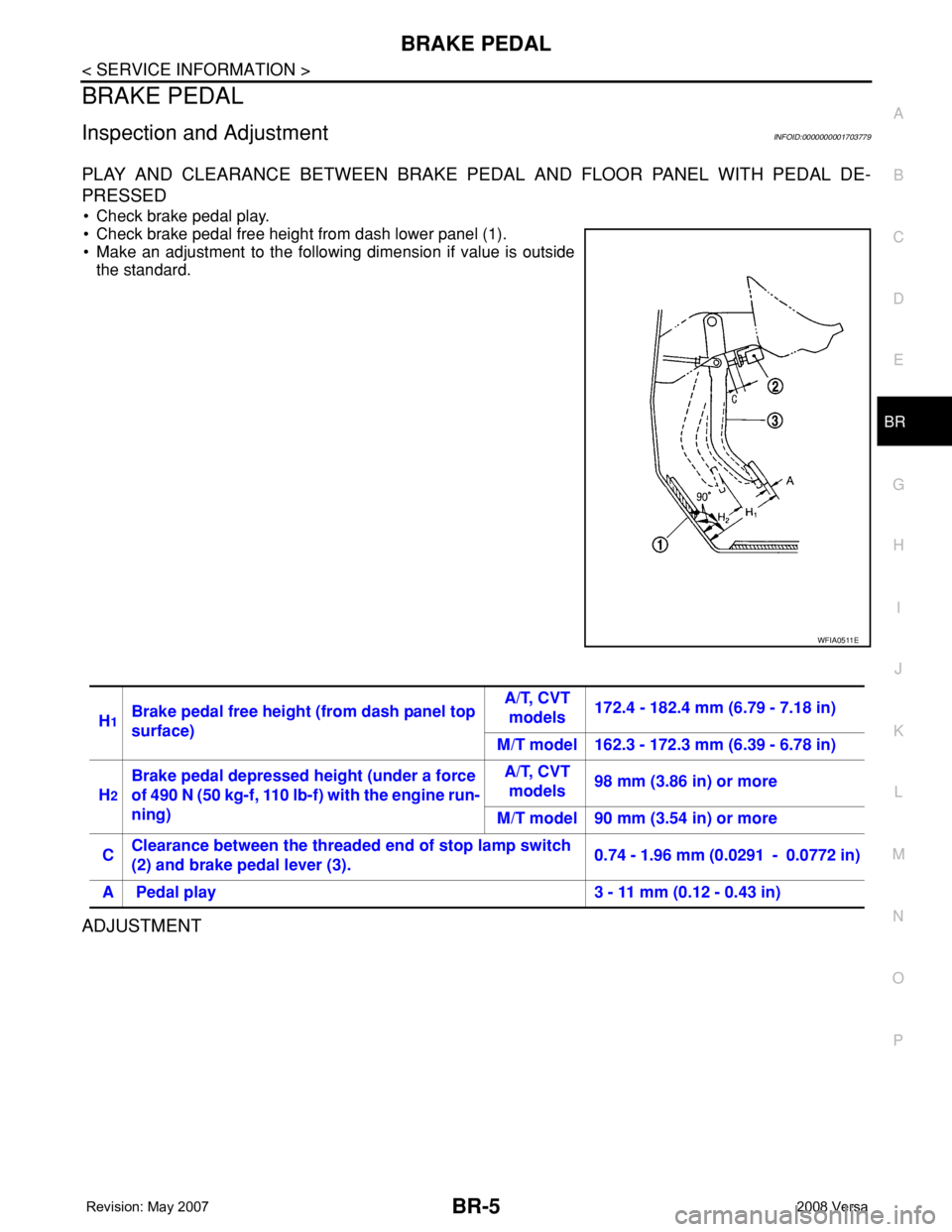
• Check brake pedal play.
• Check brake pedal free height from dash lower panel (1).
• Make an adjustment to the following dimension if value is outside
the standard.
ADJUSTMENT
WFIA0511E
H1Brake pedal free height (from dash panel top
surface)A/T, CVT
models172.4 - 182.4 mm (6.79 - 7.18 in)
M/T model 162.3 - 172.3 mm (6.39 - 6.78 in)
H
2
Brake pedal depressed height (under a force
of 490 N (50 kg-f, 110 lb-f) with the engine run-
ning)A/T, CVT
models98 mm (3.86 in) or more
M/T model 90 mm (3.54 in) or more
CClearance between the threaded end of stop lamp switch
(2) and brake pedal lever (3).0.74 - 1.96 mm (0.0291 - 0.0772 in)
A Pedal play 3 - 11 mm (0.12 - 0.43 in)
Page 737 of 2771
BR-6
< SERVICE INFORMATION >
BRAKE PEDAL
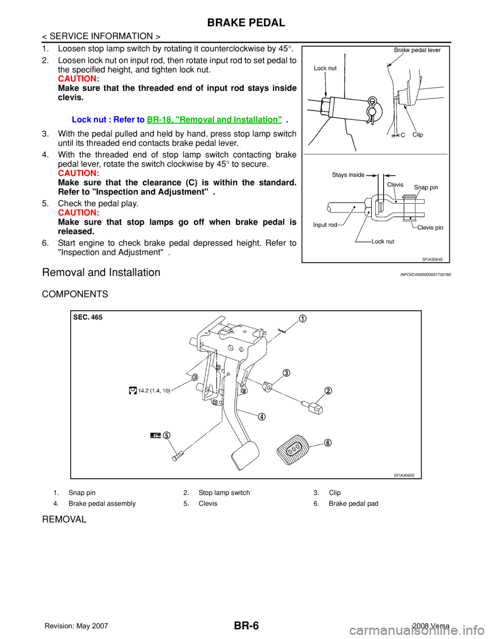
1. Loosen stop lamp switch by rotating it counterclockwise by 45°.
2. Loosen lock nut on input rod, then rotate input rod to set pedal to
the specified height, and tighten lock nut.
CAUTION:
Make sure that the threaded end of input rod stays inside
clevis.
3. With the pedal pulled and held by hand, press stop lamp switch
until its threaded end contacts brake pedal lever.
4. With the threaded end of stop lamp switch contacting brake
pedal lever, rotate the switch clockwise by 45° to secure.
CAUTION:
Make sure that the clearance (C) is within the standard.
Refer to "Inspection and Adjustment" .
5. Check the pedal play.
CAUTION:
Make sure that stop lamps go off when brake pedal is
released.
6. Start engine to check brake pedal depressed height. Refer to
"Inspection and Adjustment" .
Removal and InstallationINFOID:0000000001703780
COMPONENTS
REMOVAL
Lock nut : Refer to BR-18, "Removal and Installation" .
SFIA3064E
1. Snap pin 2. Stop lamp switch 3. Clip
4. Brake pedal assembly 5. Clevis 6. Brake pedal pad
SFIA3065E
Page 738 of 2771
BRAKE PEDAL
BR-7
< SERVICE INFORMATION >
C
D
E
G
H
I
J
K
L
MA
B
BR
N
O
P
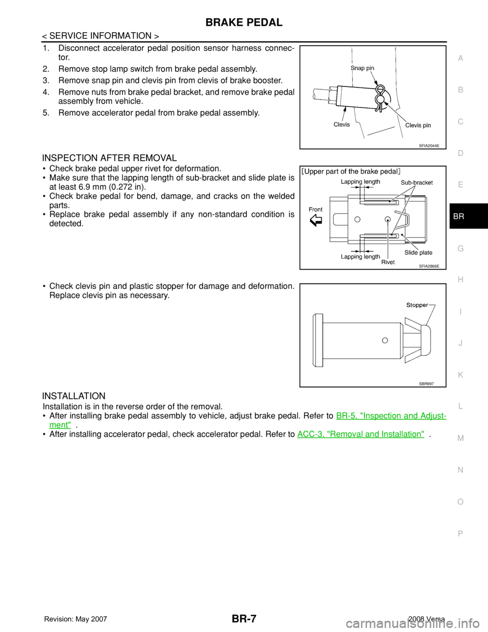
1. Disconnect accelerator pedal position sensor harness connec-
tor.
2. Remove stop lamp switch from brake pedal assembly.
3. Remove snap pin and clevis pin from clevis of brake booster.
4. Remove nuts from brake pedal bracket, and remove brake pedal
assembly from vehicle.
5. Remove accelerator pedal from brake pedal assembly.
INSPECTION AFTER REMOVAL
• Check brake pedal upper rivet for deformation.
• Make sure that the lapping length of sub-bracket and slide plate is
at least 6.9 mm (0.272 in).
• Check brake pedal for bend, damage, and cracks on the welded
parts.
• Replace brake pedal assembly if any non-standard condition is
detected.
• Check clevis pin and plastic stopper for damage and deformation.
Replace clevis pin as necessary.
INSTALLATION
Installation is in the reverse order of the removal.
• After installing brake pedal assembly to vehicle, adjust brake pedal. Refer to BR-5, "
Inspection and Adjust-
ment" .
• After installing accelerator pedal, check accelerator pedal. Refer to ACC-3, "
Removal and Installation" .
SFIA2044E
SFIA2866E
SBR997
Page 739 of 2771

BR-8
< SERVICE INFORMATION >
BRAKE FLUID
BRAKE FLUID
On Board InspectionINFOID:0000000001703781
CHECKING BRAKE FLUID LEVEL
• Make sure the fluid level in the reservoir tank is within the standard
(between MAX and MIN lines).
• Visually check around the reservoir tank for fluid leakage.
• If fluid level is excessively low, check brake system for fluid leak-
age.
• Release parking brake lever and see if brake warning lamp goes
off. If not, check brake system for fluid leakage.
Drain and RefillINFOID:0000000001703782
CAUTION:
• Refill using recommended brake fluid. Refer to MA-10
.
• Never reuse drained brake fluid.
• Be careful not to splash brake fluid on painted areas; it may cause paint damage. If brake fluid is
splashed on painted areas, immediately wipe them with cloth and wash it away with water.
• Before working, disconnect connectors of ABS actuator and electric unit (control unit) or battery
cable from the negative terminal.
1. Connect a vinyl tube to bleed valve.
2. Depress the brake pedal, loosen the bleed valve, and gradually
remove the brake fluid.
3. Clean inside of reservoir tank, and refill with new brake fluid.
4. Loosen bleed valve, depress brake pedal slowly to full stroke
and then release it. Repeat the procedure every 2 or 3 seconds
until the new brake fluid comes out, then close the bleed valve
while depressing the brake pedal. Repeat the same procedure
for each wheel.
5. Bleed air. Refer to BR-8, "
Bleeding Brake System" .
Bleeding Brake SystemINFOID:0000000001703783
CAUTION:
• While bleeding, pay attention to master cylinder fluid level.
• Before working, disconnect connectors of ABS actuator and electric unit (control unit) or the battery
cable from the negative terminal.
1. Connect a vinyl tube to the rear right bleed valve.
2. Fully depress brake pedal 4 to 5 times.
SFIA3067E
WFIA0512E
WFIA0513E
Page 740 of 2771

BRAKE FLUID
BR-9
< SERVICE INFORMATION >
C
D
E
G
H
I
J
K
L
MA
B
BR
N
O
P
3. With brake pedal depressed, loosen bleed valve to let the air out, and then tighten it immediately.
4. Repeat steps 2, 3 until no more air comes out.
5. Tighten bleed valve to specified torque. Refer to BR-23, "
Component" (front disc brake), BR-29, "Compo-
nent" (rear drum brake).
6. Following the steps 1 to 5 above, with master cylinder reservoir tank filled at least half way, bleed air from
the rear right, front left, rear left, and front right brake, in that order.