NISSAN TIIDA 2009 Service Repair Manual
TIIDA 2009
NISSAN
NISSAN
https://www.carmanualsonline.info/img/5/57398/w960_57398-0.png
NISSAN TIIDA 2009 Service Repair Manual
Trending: oil pressure, door, p2135, spare wheel, wiring driver door, manual transmission, radio
Page 271 of 4331
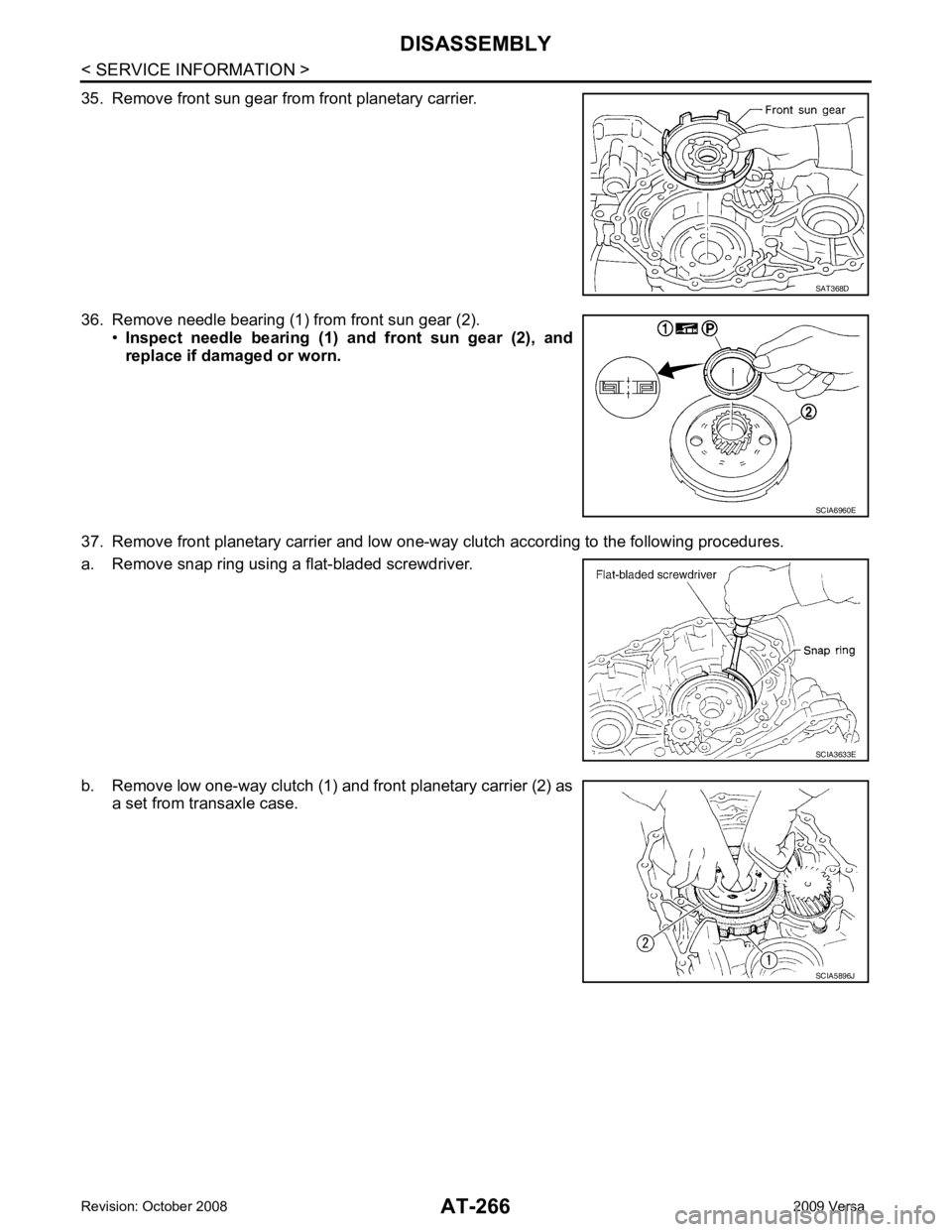
SCIA6960E
SCIA3633E
SCIA5896J
Page 272 of 4331
AT
N
O P
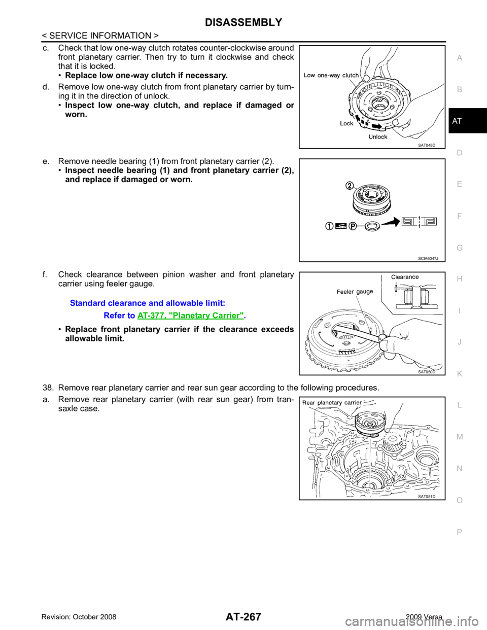
c. Check that low one-way clutch rotates counter-clockwise around
front planetary carrier. Then try to turn it clockwise and check
that it is locked.
• Replace low one-way clutch if necessary.
d. Remove low one-way clutch from front planetary carrier by turn- ing it in the direction of unlock.
• Inspect low one-way clutch , and replace if damaged or
worn.
e. Remove needle bearing (1) from front planetary carrier (2). •Inspect needle bearing (1) a nd front planetary carrier (2),
and replace if damaged or worn.
f. Check clearance between pinion washer and front planetary carrier using feeler gauge.
• Replace front planetary carrier if the clearance exceeds
allowable limit.
38. Remove rear planetary carrier and rear sun gear according to the following procedures.
a. Remove rear planetary carrier (with rear sun gear) from tran- saxle case. SCIA6047J
Planetary Carrier " .
SAT051D
Page 273 of 4331
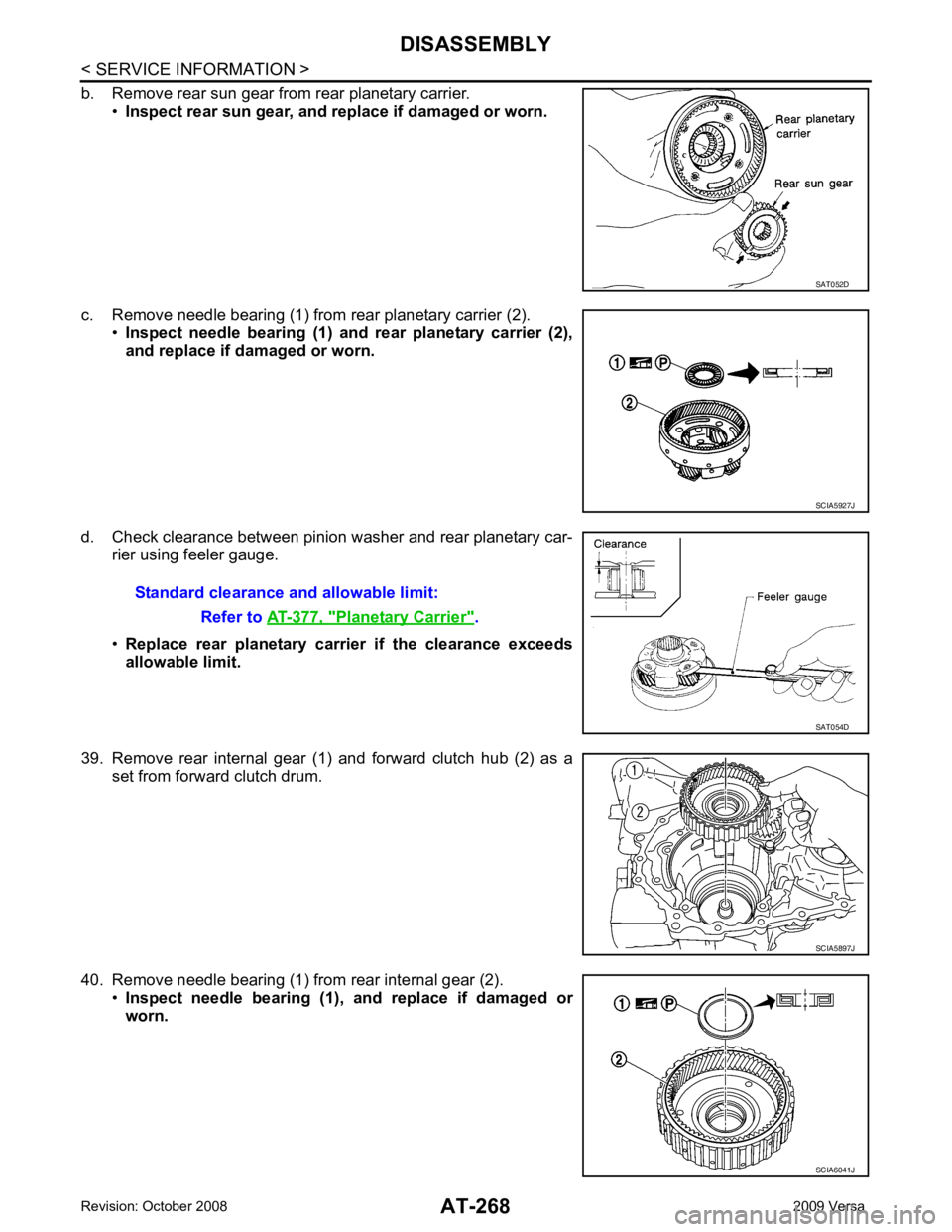
SCIA5927J
Planetary Carrier " .
SCIA6041J
Page 274 of 4331
AT
N
O P
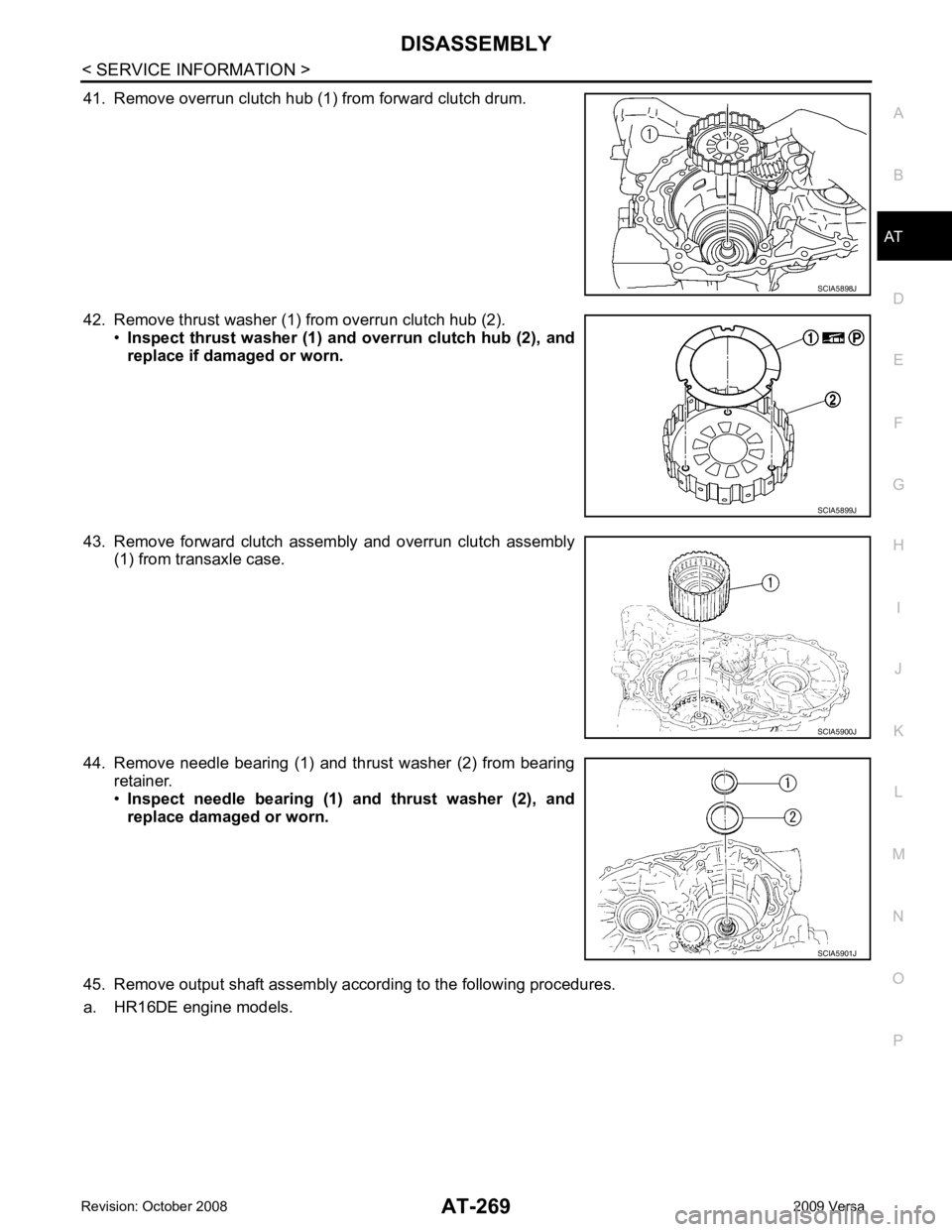
41. Remove overrun clutch hub (1
) from forward clutch drum.
42. Remove thrust washer (1) from overrun clutch hub (2). •Inspect thrust washer (1) and overrun clutch hub (2), and
replace if damaged or worn.
43. Remove forward clutch assembly and overrun clutch assembly (1) from transaxle case.
44. Remove needle bearing (1) and thrust washer (2) from bearing retainer.
• Inspect needle bearing (1) an d thrust washer (2), and
replace damaged or worn.
45. Remove output shaft assembly according to the following procedures.
a. HR16DE engine models. SCIA5900J
Page 275 of 4331
Page 276 of 4331
AT
N
O P
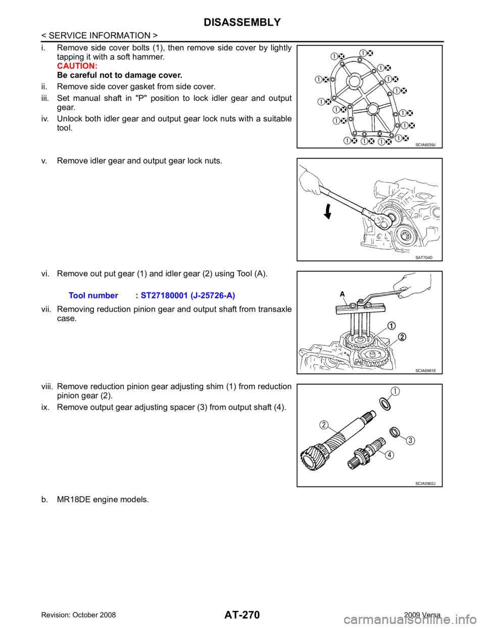
i. Remove side cover bolts (A) and (B).
CAUTION:
• Do not mix bolts (A) and (B).
• Always replace bolts (A) as they are self-sealing bolts.
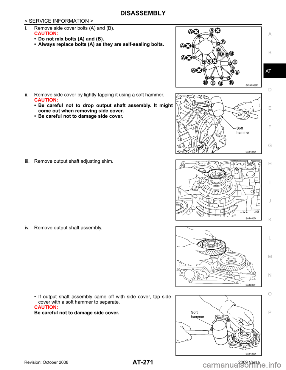
ii. Remove side cover by lightly tapping it using a soft hammer. CAUTION:
• Be careful not to drop output shaft assembly. It might
come out when removing side cover.
• Be careful not to damage side cover.
iii. Remove output shaft adjusting shim.
iv. Remove output shaft assembly.
• If output shaft assembly came off with side cover, tap side-cover with a soft hammer to separate.
CAUTION:
Be careful not to damage side cover. SAT434D
SAT440D
SAT435D
Page 277 of 4331
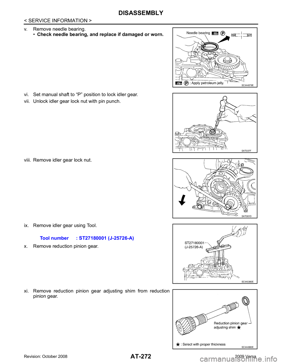
SAT037F
SAT061D
SCIA4880E
Page 278 of 4331
AT
N
O P
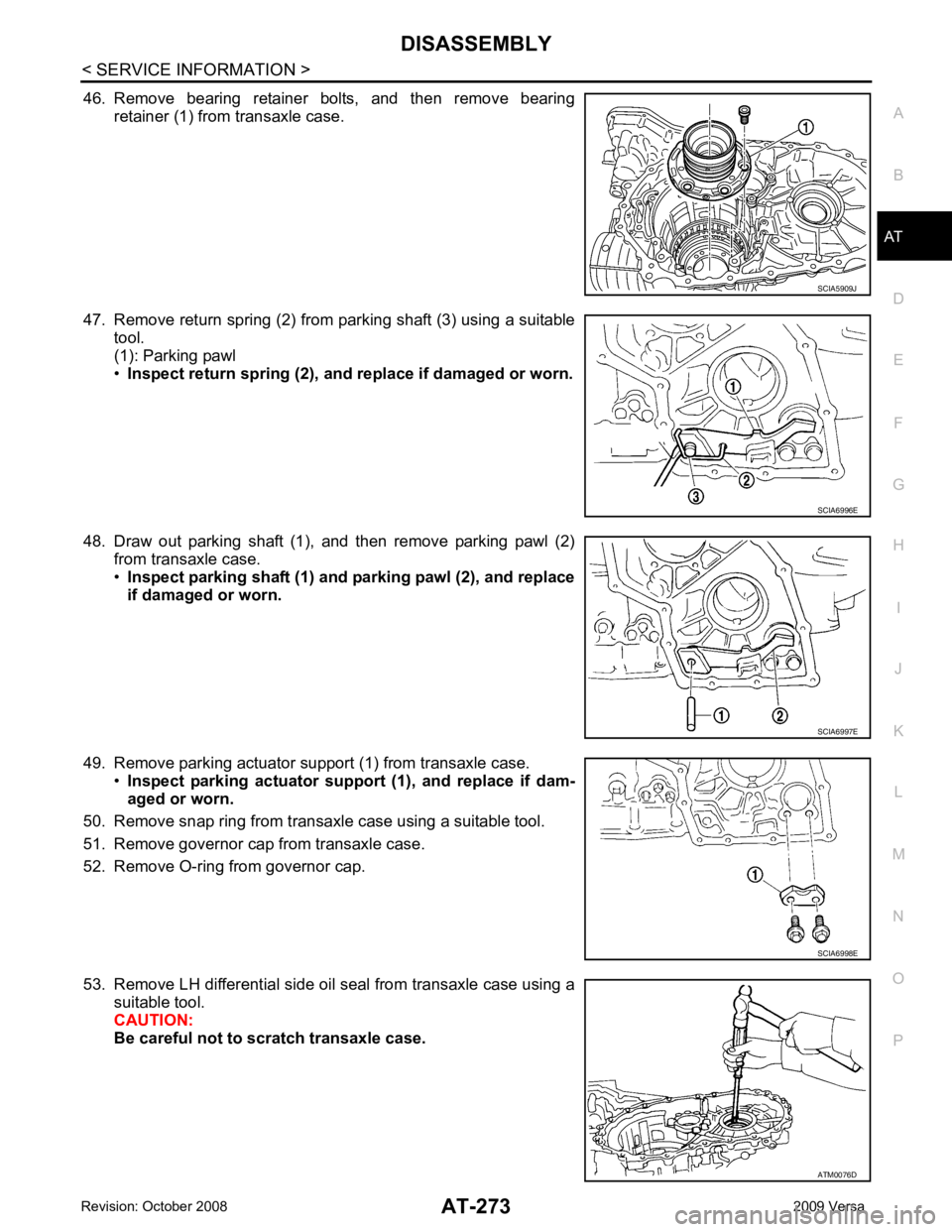
46. Remove bearing retainer bolts, and then remove bearing
retainer (1) from transaxle case.
47. Remove return spring (2) from parking shaft (3) using a suitable tool.
(1): Parking pawl
• Inspect return spring (2), and replace if damaged or worn.
48. Draw out parking shaft (1), and then remove parking pawl (2) from transaxle case.
• Inspect parking shaft (1) and parking pawl (2), and replace
if damaged or worn.
49. Remove parking actuator support (1) from transaxle case. •Inspect parking actuator sup port (1), and replace if dam-
aged or worn.
50. Remove snap ring from transaxle case using a suitable tool.
51. Remove governor cap from transaxle case.
52. Remove O-ring from governor cap.
53. Remove LH differential side oil seal from transaxle case using a suitable tool.
CAUTION:
Be careful not to scratch transaxle case. ATM0076D
Page 279 of 4331
Page 280 of 4331
AT
N
O P
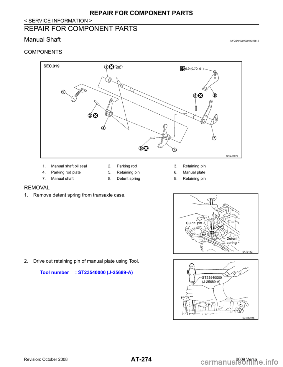
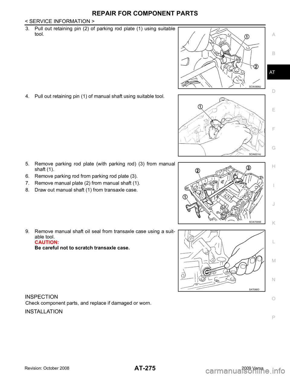
3. Pull out retaining pin (2) of parking rod plate (1) using suitable
tool.
4. Pull out retaining pin (1) of manual shaft using suitable tool.
5. Remove parking rod plate (with parking rod) (3) from manual shaft (1).
6. Remove parking rod from parking rod plate (3).
7. Remove manual plate (2) from manual shaft (1).
8. Draw out manual shaft (1) from transaxle case.
9. Remove manual shaft oil seal from transaxle case using a suit- able tool.
CAUTION:
Be careful not to scratch transaxle case.
INSPECTION Check component parts, and replace if damaged or worn.
INSTALLATION SCIA6514J
Trending: parking brake, Cooling fan, trip computer, brake fluid, tire type, suspension, belt
