NISSAN TIIDA 2009 Service Repair Manual
Manufacturer: NISSAN, Model Year: 2009, Model line: TIIDA, Model: NISSAN TIIDA 2009Pages: 4331, PDF Size: 58.04 MB
Page 381 of 4331
![NISSAN TIIDA 2009 Service Repair Manual Number of drive plates
5
Number of driven plates 5
Drive plate thickness [mm (in)] Standard 1.8 (0.071)
Allowable limit 1.6 (0.063)
Driven plate thickness [mm (in)] Standard 2.0 (0.079)
Clearance [mm NISSAN TIIDA 2009 Service Repair Manual Number of drive plates
5
Number of driven plates 5
Drive plate thickness [mm (in)] Standard 1.8 (0.071)
Allowable limit 1.6 (0.063)
Driven plate thickness [mm (in)] Standard 2.0 (0.079)
Clearance [mm](/img/5/57398/w960_57398-380.png)
Number of drive plates
5
Number of driven plates 5
Drive plate thickness [mm (in)] Standard 1.8 (0.071)
Allowable limit 1.6 (0.063)
Driven plate thickness [mm (in)] Standard 2.0 (0.079)
Clearance [mm (in)] Standard 0.45 - 0.85 (0.0177 - 0.0335)
Allowable limit 1.85 (0.0728) Number of drive plates
3
Number of driven plates 4
Drive plate thickness [mm (in)] Standard 1.6 (0.063)
Allowable limit 1.4 (0.055)
Driven plate thickness [mm (in)] Standard 2.0 (0.079)
Clearance [mm (in)] Standard 1.0 - 1.4 (0.039 - 0.055)
Allowable limit 2.0 (0.079) Applied model HR16DE engine MR18DE engine
Number of drive plates 4 5
Number of driven plates 4 5
Drive plate thickness [mm
(in)] Standard 2.0 (0.079) 2.0 (0.079)
Allowable limit 1.8 (0.071) 1.8 (0.071)
Driven plate thickness [mm
(in)] Standard 2.0 (0.079) 2.0 (0.079)
Clearance [mm (in)] Standard 1.4 - 1.8 (0.055 - 0.071) 1.4 - 1.8 (0.055 - 0.071)
Allowable limit 2.6 (0.102) 2.8 (0.110) Anchor end pin tightening torque [N·m (kg-m, in-lb)] 4.9 (0.50, 43)
Number of returning revolutions for anchor end pin 2.5
Lock nut tightening torque [N·m (kg-m, ft-lb)] 33.9 (3.5, 25)
Page 382 of 4331
AT
N
O P
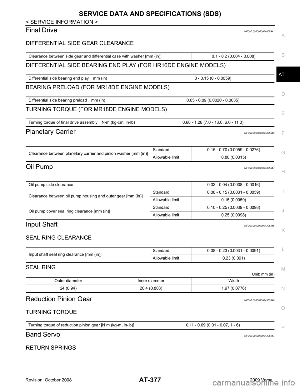
Final Drive
INFOID:0000000004807941
DIFFERENTIAL SIDE GEAR CLEARANCE
DIFFERENTIAL SIDE BEARING END PL AY (FOR HR16DE ENGINE MODELS)
BEARING PRELOAD (FOR MR18DE ENGINE MODELS)
TURNING TORQUE (FOR MR18DE ENGINE MODELS)
Planetary Carrier INFOID:0000000004305543
Oil Pump INFOID:0000000004305544
Input Shaft INFOID:0000000004305545
SEAL RING CLEARANCE
SEAL RING Unit: mm (in)
Reduction Pinion Gear INFOID:0000000004305546
TURNING TORQUE
Band Servo INFOID:0000000004305547
RETURN SPRINGS Clearance between side gear and differential case with washer [mm (in)] 0.1 - 0.2 (0.004 - 0.008) Differential side bearing end play mm (in) 0 - 0.15 (0 - 0.0059)
Differential side bearing preload mm (in) 0.05 - 0.09 (0.0020 - 0.0035)
Turning torque of final drive assembly N-m (kg-cm, in-lb) 0.68 - 1.26 (7.0 - 13.0, 6.0 - 11.0)
Clearance between planetary carrier and pinion washer [mm (in)]
Standard 0.15 - 0.70 (0.0059 - 0.0276)
Allowable limit 0.80 (0.0315) Oil pump side clearance
0.02 - 0.04 (0.0008 - 0.0016)
Clearance between oil pump housing and outer gear [mm (in)] Standard 0.08 - 0.15 (0.0031 - 0.0059)
Allowable limit 0.15 (0.0059)
Oil pump cover seal ring clearance [mm (in)] Standard 0.10 - 0.25 (0.0039 - 0.0098)
Allowable limit 0.25 (0.0098) Input shaft seal ring clearance [mm (in)]
Standard 0.08 - 0.23 (0.0031 - 0.0091)
Allowable limit 0.23 (0.091) Outer diameter Inner diameter Width
24 (0.94) 20.4 (0.803) 1.97 (0.0776) Turning torque of reduction pinion gear [N·m (kg-m, in-lb)] 0.11 - 0.69 (0.01 - 0.07, 1 - 6)
Page 383 of 4331
![NISSAN TIIDA 2009 Service Repair Manual Output shaft seal ring clearance [mm (in)]
Standard 0.10 - 0.25 (0.0039 - 0.0098)
Allowable limit 0.25 (0.0098) Outer diameter Inner diameter Width
29.5 (1.161) 26.2 (1.031) 1.95 (0.0768) Turning torq NISSAN TIIDA 2009 Service Repair Manual Output shaft seal ring clearance [mm (in)]
Standard 0.10 - 0.25 (0.0039 - 0.0098)
Allowable limit 0.25 (0.0098) Outer diameter Inner diameter Width
29.5 (1.161) 26.2 (1.031) 1.95 (0.0768) Turning torq](/img/5/57398/w960_57398-382.png)
Output shaft seal ring clearance [mm (in)]
Standard 0.10 - 0.25 (0.0039 - 0.0098)
Allowable limit 0.25 (0.0098) Outer diameter Inner diameter Width
29.5 (1.161) 26.2 (1.031) 1.95 (0.0768) Turning torque of output shaft ·m (kg-m, in-lb) 0.25 - 0.88 (0.03 - 0.08, 3 - 7)
Output shaft end play mm (in) 0 - 0.5 (0 - 0.020)
Bearing retainer seal ring clearance [mm (in)]
Standard 0.10 - 0.27 (0.0039 - 0.0106)
Allowable limit 0.27 (0.0106) Total end play [mm (in)] 0.25 - 0.55 (0.0098 - 0.0217)
Reverse clutch end play [mm (in)] 0.65 - 1.0 (0.0256 - 0.039)
Engine
HR16DE MR18DE
Distance between end of converter housing and torque converter [mm (in)] 16.2 (0.638) 14.4 (0.567) Gear position 1 2 3 4
Shift solenoid valve A ON (Closed) OFF (Open) OFF (Open) ON (Closed)
Shift solenoid valve B ON (Closed) ON (Closed) OFF (Open) OFF (Open)
Page 384 of 4331
AT
N
O P
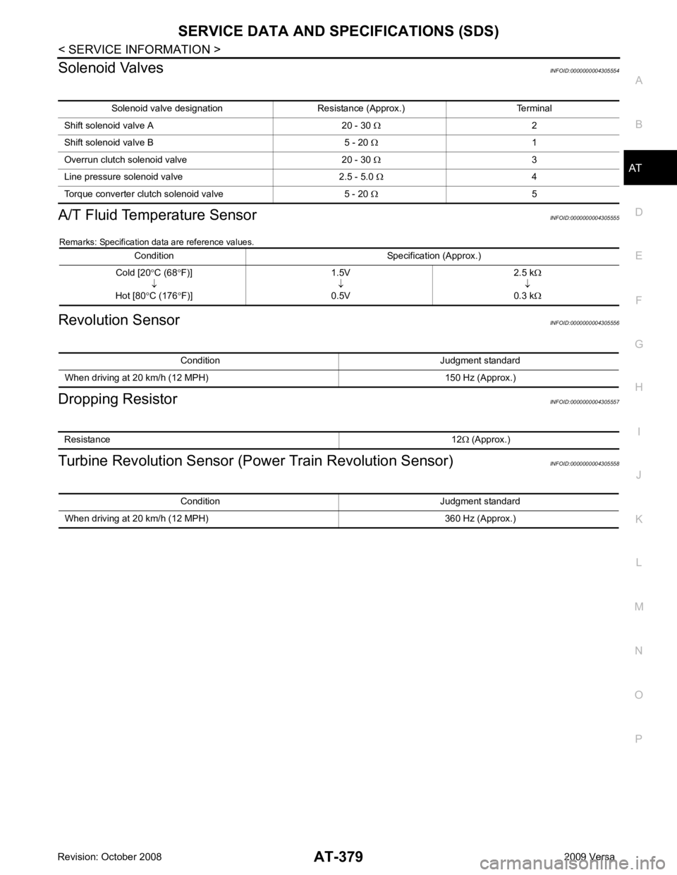
Solenoid Valves
INFOID:0000000004305554
A/T Fluid Temperature Sensor INFOID:0000000004305555
Remarks: Specification data are reference values.
Revolution Sensor INFOID:0000000004305556
Dropping Resistor INFOID:0000000004305557
Turbine Revolution Sensor (Power Train Revolution Sensor) INFOID:0000000004305558
Solenoid valve designation Resistance (Approx.) Terminal
Shift solenoid valve A 20 - 30 Ω2
Shift solenoid valve B 5 - 20 Ω1
Overrun clutch solenoid valve 20 - 30 Ω3
Line pressure solenoid valve 2.5 - 5.0 Ω4
Torque converter clutch solenoid valve 5 - 20 Ω5Condition Specification (Approx.)
Cold [20 °C (68 °F)]
↓
Hot [80 °C (176 °F)] 1.5V
↓
0.5V 2.5 k
Ω
↓
0.3 k Ω Resistance
12Ω (Approx.) Condition Judgment standard
When driving at 20 km/h (12 MPH) 360 Hz (Approx.)
Page 385 of 4331
AV
N
O P
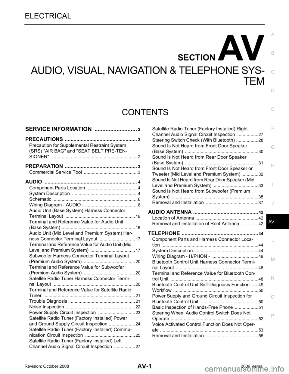
CONTENTS
AUDIO, VISUAL, NAVIGATION & TELEPHONE SYS-
TEM
SERVICE INFORMATION .. ..........................2
PRECAUTIONS .............................................. .....2
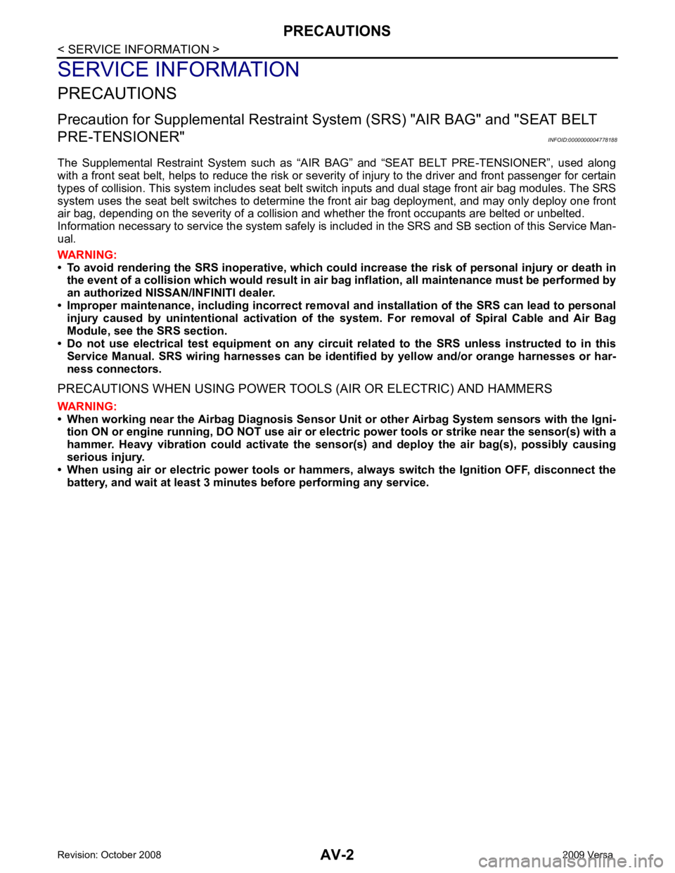
Precaution for Supplemental Restraint System
(SRS) "AIR BAG" and "SEAT BELT PRE-TEN-
SIONER" ............................................................. ......
2
PREPARATION .............................................. .....3
Commercial Service Tool .................................... ......3
AUDIO ............................................................ .....4
Component Parts Location .................................. ......4
System Description ............................................. ......4
Schematic ........................................................... ......6
Wiring Diagram - AUDIO - ................................... ......8
Audio Unit (Base System) Harness Connector
Terminal Layout .................................................. ....
16
Terminal and Reference Value for Audio Unit
(Base System) ..................................................... ....
16
Audio Unit (Mid Level and Premium System) Har-
ness Connector Terminal Layout ........................ ....
17
Terminal and Reference Value for Audio Unit (Mid
Level and Premium System) ............................... ....
17
Subwoofer Harness Connector Terminal Layout
(Premium Audio System) .................................... ....
20
Terminal and Reference Value for Subwoofer
(Premium Audio System) .................................... ....
20
Satellite Radio Tuner Ha rness Connector Termi-
nal Layout ............................................................ ....
20
Terminal and Reference Value for Satellite Radio
Tuner ................................................................... ....
21
Trouble Diagnosis ............................................... ....21
Noise Inspection .................................................. ....22
Power Supply Circuit Inspection ......................... ....23
Satellite Radio Tuner (Fac tory Installed) Power
and Ground Supply Circuit Inspection ................. ....
24
Satellite Radio Tuner (Fac tory Installed) Commu-
nication Circuit Inspection ................................... ....
25
Satellite Radio Tuner (Fac tory Installed) Left
Channel Audio Signal Circuit Inspection ............. ....
27 Satellite Radio Tuner (Fac
tory Installed) Right
Channel Audio Signal Circuit Inspection ............. ....
27
Steering Switch Check (With Bluetooth) .............. ....28
Sound Is Not Heard from Front Door Speaker
(Base System) ..................................................... ....
30
Sound Is Not Heard from Rear Door Speaker
(Base System) ..................................................... ....
31
Sound Is Not Heard from Front Door Speaker or
Tweeter (Mid Level and Premium System) .............
32
Sound Is Not Heard from Rear Door Speaker (Mid
Level and Premium System) ............................... ....
33
Sound Is Not Heard from Subwoofer (Premium
System) ............................................................... ....
35
Removal and Installation ..................................... ....37
AUDIO ANTENNA ............................................. 42
Location of Antenna ............................................. ....42
Removal and Installation of Roof Antenna ..............42
TELEPHONE ..................................................... 44
Component Parts and Harness Connector Loca-
tion ....................................................................... ....
44
System Description .............................................. ....44
Wiring Diagram - H/PHON - ................................ ....46
Bluetooth Control Unit Harness Connector Termi-
nal Layout ............................................................ ....
48
Terminal and Reference Value for Bluetooth Con-
trol Unit ................................................................ ....
48
Bluetooth Control Unit Se lf-Diagnosis Function ......49
Workflow .............................................................. ....50
Power Supply and Ground Circuit Inspection for
Bluetooth Control Unit .. ...........................................
50
Basic Inspection of Hands-Free Phone ............... ....51
Steering Wheel Audio Co ntrol Switch Does Not
Operate ................................................................ ....
52
Voice Activated Control Fu nction Does Not Oper-
ate ........................................................................ ....
53
Removal and Installation ..................................... ....55
Page 386 of 4331
Page 387 of 4331
AV
N
O P
PREPARATION
Commercial Service Tool INFOID:0000000004306953
Tool name Description
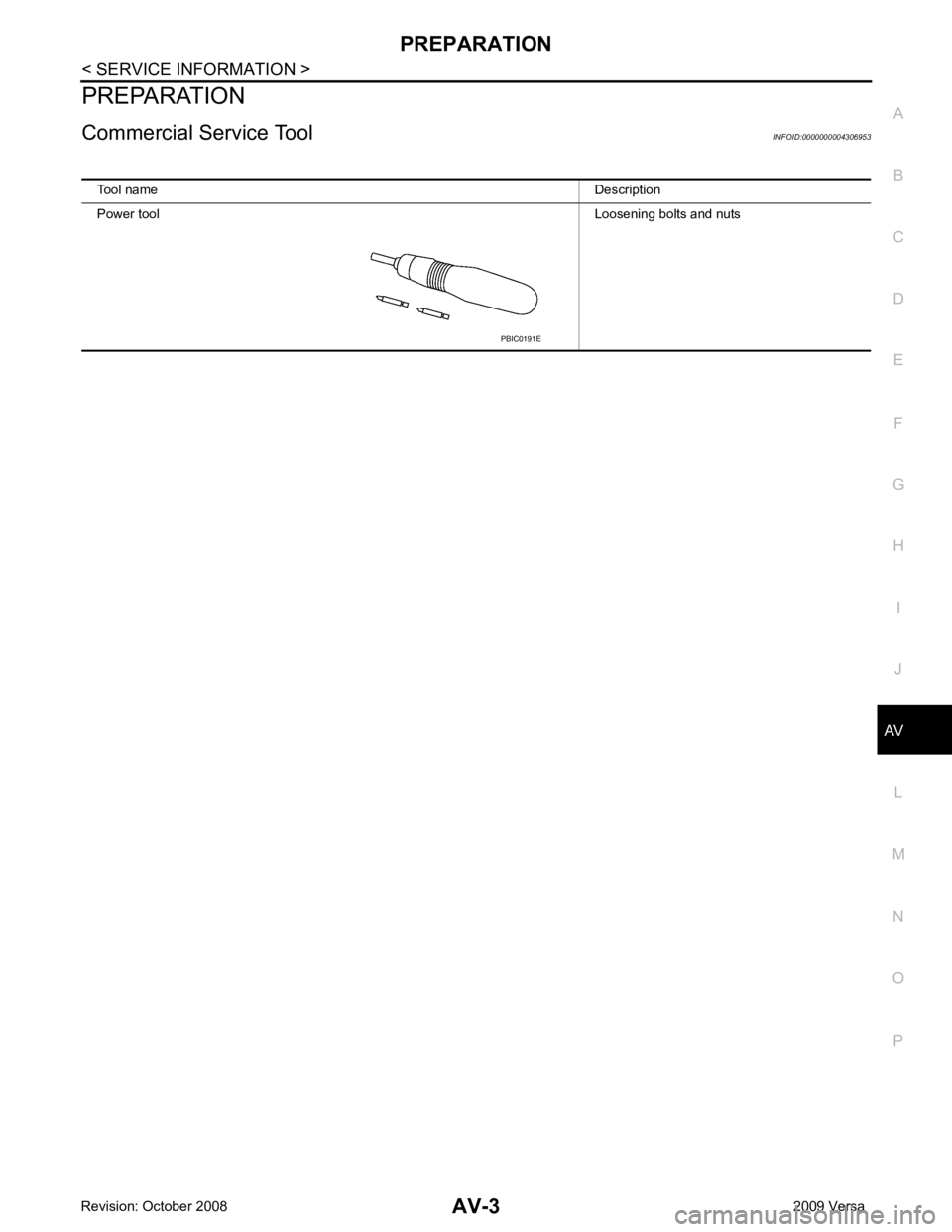
Power tool Loosening bolts and nuts
Page 388 of 4331
Page 389 of 4331
AV
N
O P
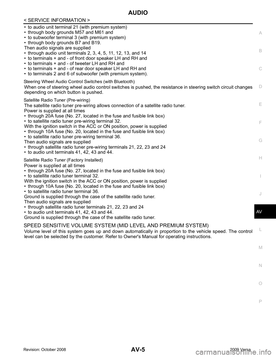
• to audio unit terminal 21 (with premium system)
• through body grounds M57 and M61 and
• to subwoofer terminal 3 (with premium system)
• through body grounds B7 and B19.
Then audio signals are supplied
• through audio unit terminals 2, 3, 4, 5, 11, 12, 13, and 14
• to terminals + and - of front door speaker LH and RH and
• to terminals + and - of tweeter LH and RH and
• to terminals + and - of rear door speaker LH and RH and
• to terminals 2 and 6 of subwoofer (with premium system).
Steering Wheel Audio Contro l Switches (with Bluetooth)
When one of steering wheel audio control switches is pus hed, the resistance in steering switch circuit changes
depending on which button is pushed.
Satellite Radio Tuner (Pre-wiring) The satellite radio tuner pre-wiring allows connection of a satellite radio tuner.
Power is supplied at all times
• through 20A fuse (No. 27, located in the fuse and fusible link box)
• to satellite radio tuner pre-wiring terminal 32.
With the ignition switch in the ACC or ON position, power is supplied
• through 10A fuse (No. 20, located in the fuse and fusible link box)
• to satellite radio tuner pre-wiring terminal 36.
Then audio signals are supplied
• through satellite radio tuner pre-wiring terminals 21, 22, 23 and 24
• to audio unit terminals 41, 42, 43 and 44.
Satellite Radio Tuner (Factory Installed)
Power is supplied at all times
• through 20A fuse (No. 27, located in the fuse and fusible link box)
• to satellite radio tuner terminal 32.
With the ignition switch in the ACC or ON position, power is supplied
• through 10A fuse (No. 20, located in the fuse and fusible link box)
• to satellite radio tuner terminal 36.
Ground is supplied through the case of the satellite radio tuner.
Then audio signals are supplied
• through satellite radio tuner terminals 21, 22, 23 and 24
• to audio unit terminals 41, 42, 43 and 44.
Ground is supplied through the case of the satellite radio tuner.
SPEED SENSITIVE VOLUME SYSTEM (MID LEVEL AND PREMIUM SYSTEM) Volume level of this system goes up and down automatica lly in proportion to the vehicle speed. The control
level can be selected by the customer. Refer to Owner's Manual for operating instructions.
Page 390 of 4331
B