NISSAN TIIDA 2009 Service Repair Manual
TIIDA 2009
NISSAN
NISSAN
https://www.carmanualsonline.info/img/5/57398/w960_57398-0.png
NISSAN TIIDA 2009 Service Repair Manual
Trending: roof, alarm, air suspension, Horn, p2135, fuse diagram, engine control
Page 421 of 4331
AV
N
O P
OK or NG OK >> Replace subwoofer. Refer to
AV-37, " Removal and Installation " .
NG >> Replace audio unit. Refer to AV-37, " Removal and Installation " .
Removal and Installation INFOID:0000000004306979
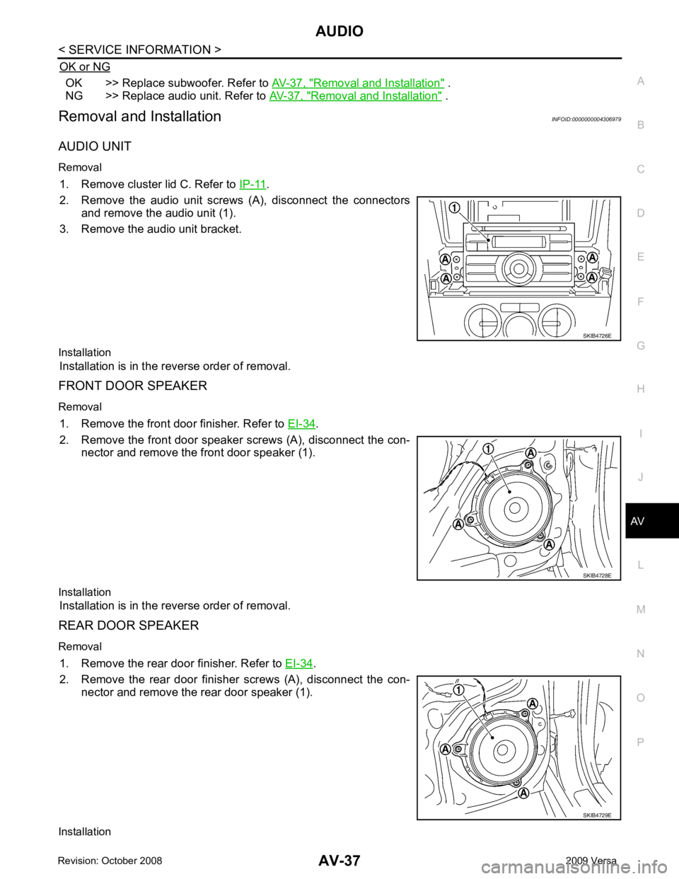
AUDIO UNIT
Removal 1. Remove cluster lid C. Refer to IP-11 .
2. Remove the audio unit screws (A), disconnect the connectors and remove the audio unit (1).
3. Remove the audio unit bracket.
Installation Installation is in the reverse order of removal.
FRONT DOOR SPEAKER
Removal 1. Remove the front door finisher. Refer to EI-34 .
2. Remove the front door speaker screws (A), disconnect the con-
nector and remove the front door speaker (1).
Installation Installation is in the reverse order of removal.
REAR DOOR SPEAKER
Removal 1. Remove the rear door finisher. Refer to EI-34 .
2. Remove the rear door finisher screws (A), disconnect the con- nector and remove the rear door speaker (1).
Installation
Page 422 of 4331
.
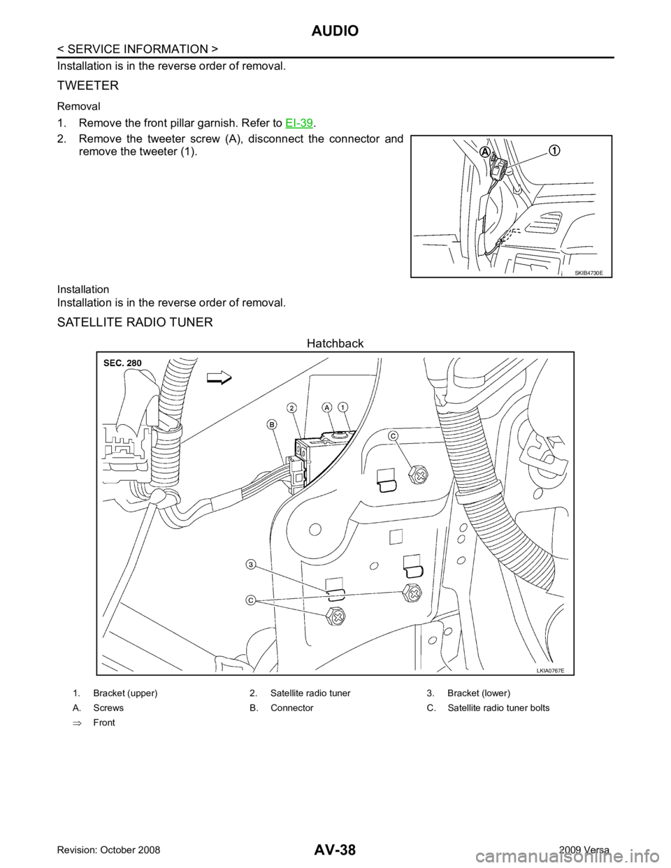
2. Remove the tweeter screw (A), disconnect the connector and remove the tweeter (1).
Installation
Installation is in the reverse order of removal.
SATELLITE RADIO TUNER
Hatchback
Page 423 of 4331
AV
N
O P
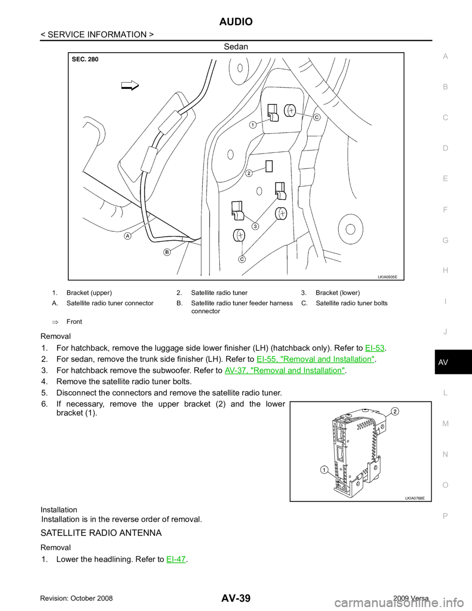
Sedan
Removal 1. For hatchback, remove the luggage side lower finisher (LH) (hatchback only). Refer to EI-53 .
2. For sedan, remove the trunk side finisher (LH). Refer to EI-55, " Removal and Installation " .
3. For hatchback remove the subwoofer. Refer to AV-37, " Removal and Installation " .
4. Remove the satellite radio tuner bolts.
5. Disconnect the connectors and remove the satellite radio tuner.
6. If necessary, remove the upper bracket (2) and the lower bracket (1).
Installation Installation is in the reverse order of removal.
SATELLITE RADIO ANTENNA
Removal 1. Lower the headlining. Refer to EI-47 .
Page 424 of 4331
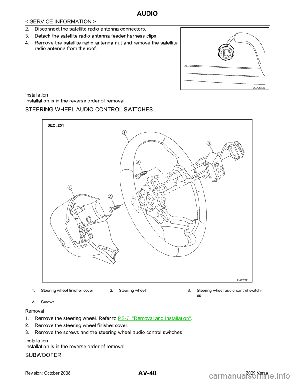
Removal and Installation " .
2. Remove the steering wheel finisher cover.
3. Remove the screws and the steering wheel audio control switches.
Installation
Installation is in the reverse order of removal.
SUBWOOFER
Page 425 of 4331
AV
N
O P
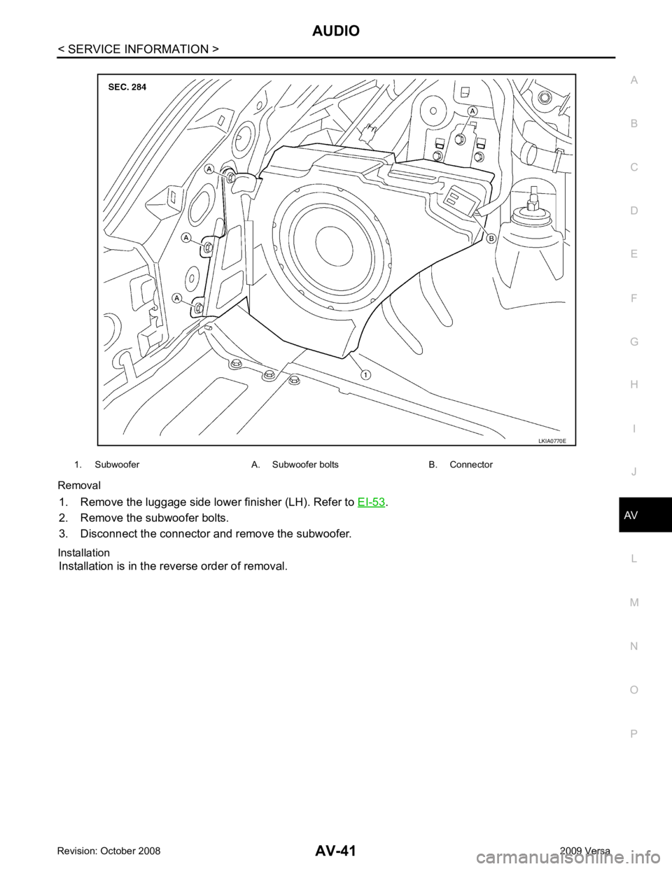
Removal
1. Remove the luggage side lower finisher (LH). Refer to EI-53 .
2. Remove the subwoofer bolts.
3. Disconnect the connector and remove the subwoofer.
Installation Installation is in the reverse order of removal. 1. Subwoofer A. Subwoofer bolts B. Connector
Page 426 of 4331
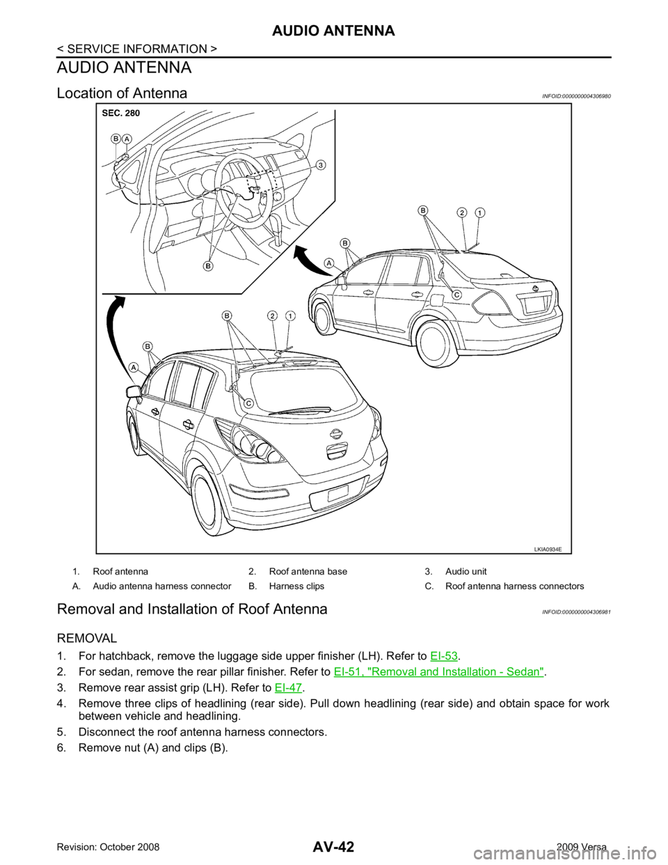
.
2. For sedan, remove the rear pillar finisher. Refer to EI-51, " Removal and Installation - Sedan " .
3. Remove rear assist grip (LH). Refer to EI-47 .
4. Remove three clips of headlining (rear side). Pull down headlining (rear side) and obtain space for work between vehicle and headlining.
5. Disconnect the roof antenna harness connectors.
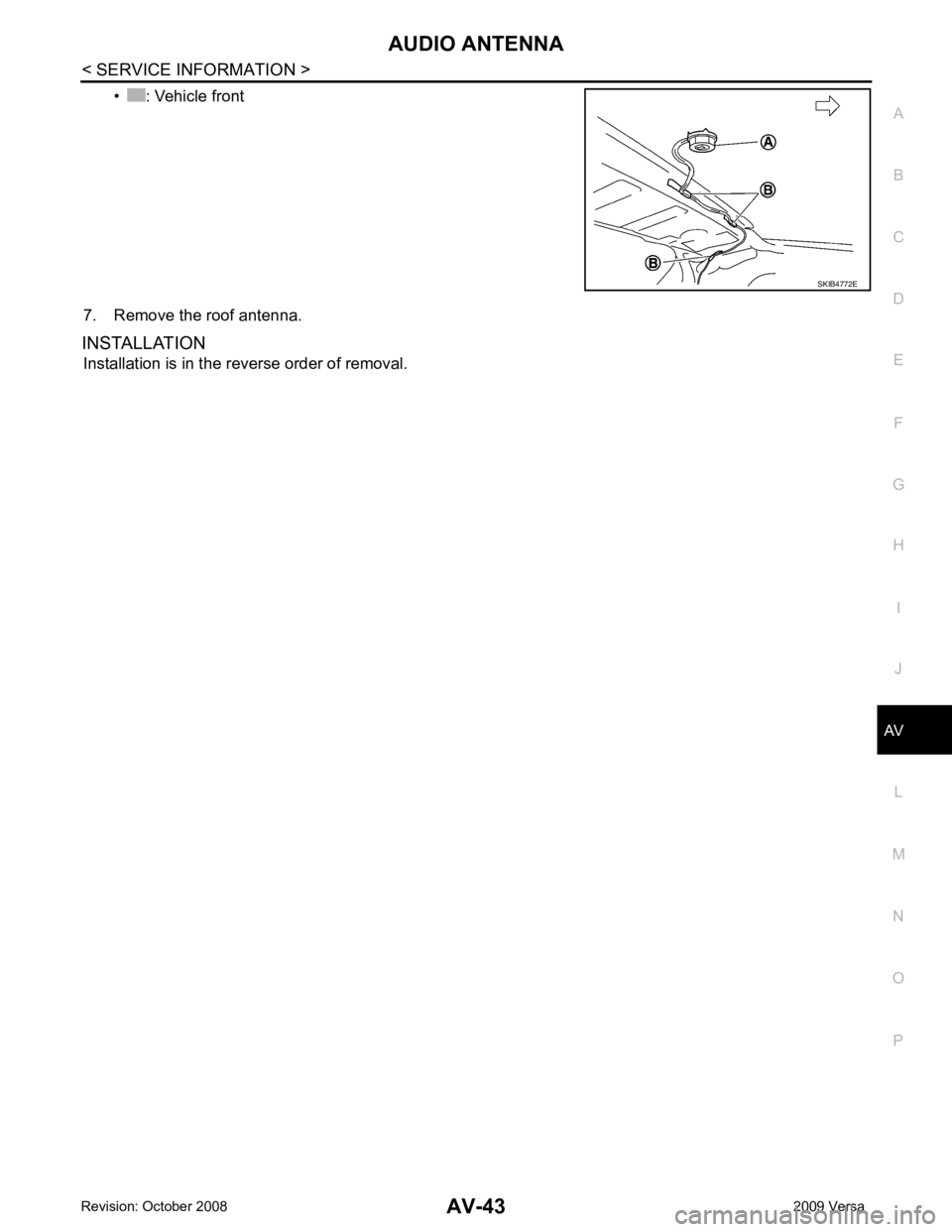
6. Remove nut (A) and clips (B).
Page 427 of 4331
AV
N
O P
• : Vehicle front
7. Remove the roof antenna.
INSTALLATION Installation is in the reverse order of removal.
Page 428 of 4331
Page 429 of 4331
AV
N
O P
tooth cellular telephones may not be recognized by t
he Bluetooth control unit. When a cellular telephone or
the Bluetooth control unit is replaced, the telephone must be paired with the Bluetooth control unit. Different
cellular telephones may have different pairing procedures. Refer to the cellular telephone operating manual.
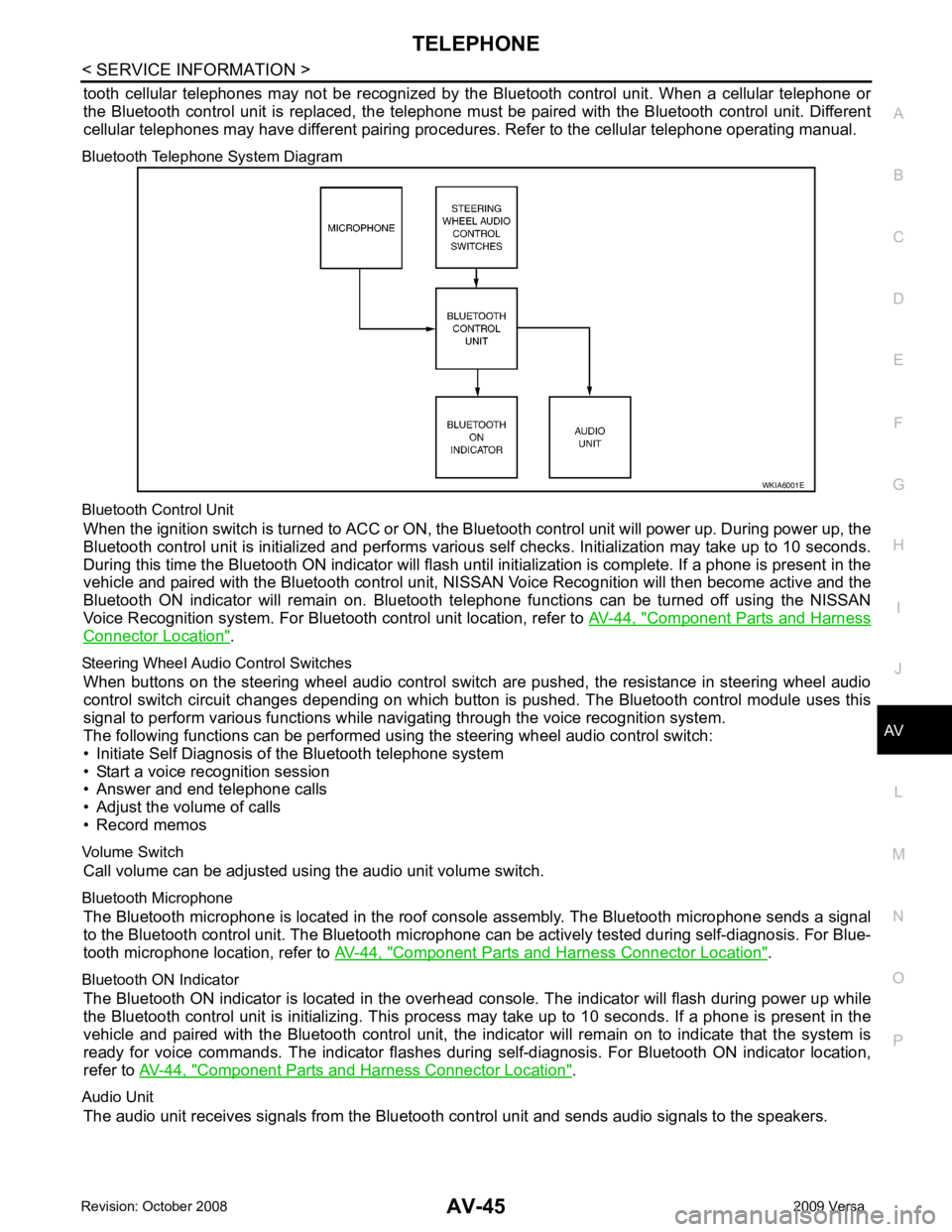
Bluetooth Telephone System Diagram
Bluetooth Control Unit When the ignition switch is turned to ACC or ON, the Bluetooth control unit will power up. During power up, the
Bluetooth control unit is initialized and performs various self checks. Initialization may take up to 10 seconds.
During this time the Bluetooth ON indicator will flash until initialization is complete. If a phone is present in the
vehicle and paired with the Bluetooth control unit, NIS SAN Voice Recognition will then become active and the
Bluetooth ON indicator will remain on. Bluetooth te lephone functions can be turned off using the NISSAN
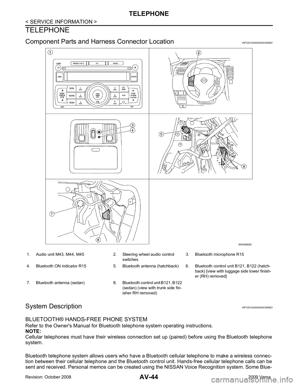
Voice Recognition system. For Bluetooth control unit location, refer to AV-44, " Component Parts and Harness
Connector Location " .
Steering Wheel Audio Control Switches When buttons on the steering wheel audio control switch are pushed, the resistance in steering wheel audio
control switch circuit changes depending on which button is pushed. The Bluetooth control module uses this
signal to perform various functions while navigating through the voice recognition system.
The following functions can be performed usi ng the steering wheel audio control switch:
• Initiate Self Diagnosis of the Bluetooth telephone system
• Start a voice recognition session
• Answer and end telephone calls
• Adjust the volume of calls
• Record memos
Volume Switch Call volume can be adjusted using the audio unit volume switch.
Bluetooth Microphone The Bluetooth microphone is located in the roof c onsole assembly. The Bluetooth microphone sends a signal
to the Bluetooth control unit. The Bluetooth microphone can be actively tested during self-diagnosis. For Blue-
tooth microphone location, refer to AV-44, " Component Parts and Harness Connector Location " .
Bluetooth ON Indicator The Bluetooth ON indicator is located in the overhead console. The indicator will flash during power up while
the Bluetooth control unit is initializing. This process may take up to 10 seconds. If a phone is present in the
vehicle and paired with the Bluetooth control unit, the indi cator will remain on to indicate that the system is
ready for voice commands. The indicator flashes duri ng self-diagnosis. For Bluetooth ON indicator location,
refer to AV-44, " Component Parts and Harness Connector Location " .
Audio Unit The audio unit receives signals from the Bluetooth control unit and sends audio signals to the speakers.
Page 430 of 4331
Trending: clock, Fuel pump relay location, air suspension, engine oil capacity, wheel, wheel alignment, reset
