NISSAN TIIDA 2009 Service Repair Manual
Manufacturer: NISSAN, Model Year: 2009, Model line: TIIDA, Model: NISSAN TIIDA 2009Pages: 4331, PDF Size: 58.04 MB
Page 4131 of 4331
SB
N
O P
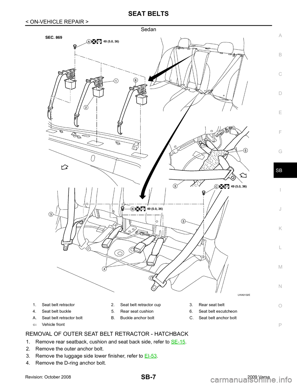
Sedan
REMOVAL OF OUTER SEAT BELT RETRACTOR - HATCHBACK 1. Remove rear seatback, cushion and seat back side, refer to SE-15 .
2. Remove the outer anchor bolt.
3. Remove the luggage side lower finisher, refer to EI-53 .
4. Remove the D-ring anchor bolt.
Page 4132 of 4331
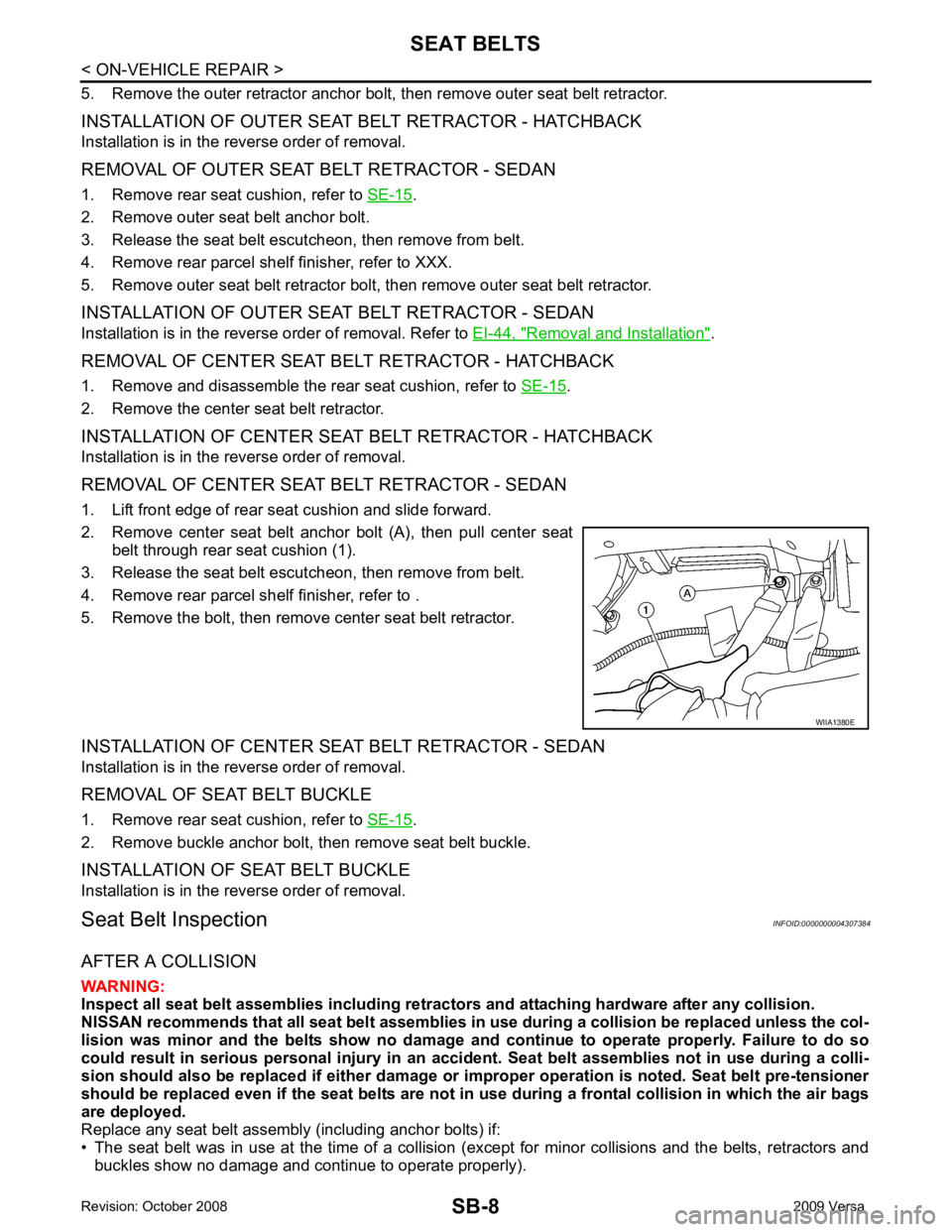
.
2. Remove outer seat belt anchor bolt.
3. Release the seat belt escutcheon, then remove from belt.
4. Remove rear parcel shelf finisher, refer to XXX.
5. Remove outer seat belt retractor bolt, then remove outer seat belt retractor.
INSTALLATION OF OUTER SEAT BELT RETRACTOR - SEDAN
Installation is in the reverse order of removal. Refer to EI-44, " Removal and Installation " .
REMOVAL OF CENTER SEAT BELT RETRACTOR - HATCHBACK
1. Remove and disassemble the rear seat cushion, refer to SE-15 .
2. Remove the center seat belt retractor.
INSTALLATION OF CENTER SEAT BELT RETRACTOR - HATCHBACK
Installation is in the reverse order of removal.
REMOVAL OF CENTER SEAT BELT RETRACTOR - SEDAN
1. Lift front edge of rear seat cushion and slide forward.
2. Remove center seat belt anchor bolt (A), then pull center seat
belt through rear seat cushion (1).
3. Release the seat belt escutcheon, then remove from belt.
4. Remove rear parcel shelf finisher, refer to .
5. Remove the bolt, then remove center seat belt retractor.
INSTALLATION OF CENTER SEAT BELT RETRACTOR - SEDAN
Installation is in the reverse order of removal.
REMOVAL OF SEAT BELT BUCKLE
1. Remove rear seat cushion, refer to SE-15 .
2. Remove buckle anchor bolt, then remove seat belt buckle.
INSTALLATION OF SEAT BELT BUCKLE
Installation is in the reverse order of removal.
Seat Belt Inspection INFOID:0000000004307384
AFTER A COLLISION
WARNING:
Inspect all seat belt assemblies in cluding retractors and attaching hardware after any collision.
NISSAN recommends that all seat belt assemblies in use during a collision be replaced unless the col-
lision was minor and the belts show no damage and continue to operate properly. Failure to do so
could result in serious personal injury in an acci dent. Seat belt assemblies not in use during a colli-
sion should also be replaced if either damage or im proper operation is noted. Seat belt pre-tensioner
should be replaced even if the seat belts are not in use during a frontal collision in which the air bags
are deployed.
Replace any seat belt assembly (including anchor bolts) if:
• The seat belt was in use at the time of a collision (except for minor collisions and the belts, retractors and
buckles show no damage and continue to operate properly).
Page 4133 of 4331
SB
N
O P
• The seat belt was damaged in an accident. (i.e. torn webbing, bent retractor or guide, etc.)
• The seat belt attaching point was damaged in an accident. Inspect the seat belt attaching area for damage or distortion and repair as necessary before installing a new seat belt assembly.
• Anchor bolts are deformed or worn out.
• The seat belt pre-tensioner should be replaced even if the seat belts are not in use during a frontal collision
in which the air bags are deployed.
PRELIMINARY CHECKS 1. Check the seat belt warning lamp/chime for proper operation as follows:
a. Switch ignition ON. The seat belt warning lamp should illuminate. Also, the seat belt warning chime should sound for about seven seconds.
b. Fasten driver's seat belt. The seat belt warni ng lamp should go out and the chime (if sounding) should
stop.
2. If the air bag warning lamp is blinking, conduct self-diagnosis using CONSULT-II, and air bag warning
lamp. Refer to SRS-19, " SRS Operation Check " .
3. Check that the seat belt retractor, seat belt anchor and buckle bolts are securely attached.
4. Check the shoulder seat belt guide and shoulder belt height adjuster for front seats. Make sure guide
swivels freely and that webbing lays flat and does not bind in guide. Make sure height adjuster operates
properly and holds securely.
5. Check retractor operation:
a. Fully extend the seat belt webbing and check for twists, tears or other damage.
b. Allow the seat belt to retract. Make sure that webbing returns smoothly and completely into the retractor. If the seat belt does not return smoothly, wipe the inside of the loops with a clean paper cloth. Dirt build-up
in the loops of the upper anchors can caus e the seat belts to retract slowly.
c. Fasten the seat belt. Check the seat belt returns sm oothly and completely to the retractor. If the webbing
does not return smoothly, the cause may be an accu mulation of dust or dirt. Use the “SEAT BELT TAPE
SET” and perform the following steps.
Inspect the front seat belt though-anchor
1. Pull the seat belt out to a length of 500 mm (19.69 in) or more.
2. Use a clip or other device to attach t he seat belt at the center pillar webbing opening.
3. Pass a thin wire though the D-ring anchor webbing opening. Hold both ends of the wire and pull taut while moving it up and down several times along the webbing opening surface to remove matter stuck
there.
4. Any dirt that cannot be removed with the wire can be removed by cleaning the opening with a clean
cloth.
5. Apply tape at the point where the webbing contacts the though-anchor webbing opening. NOTE:
Apply the tape so that there is no looseness or wrinkling.
6. Remove the clip attaching the seat bel t and check that the webbing returns smoothly.
6. Repeat steps above as necessary to check the other seat belts.
SEAT BELT RETRACTOR ON-VEHICLE CHECK
Emergency Locking Retractors (ELR) and Automatic Locking Retractors (ALR)
NOTE:
All seat belt retractors are of the Emergency Locki ng Retractors (ELR) type. In an emergency (sudden stop)
the retractor will lock and prevent the webbing from extending any further. All 3-point type seat belt retractors
except the driver's seat belt also have an Automati c Locking Retractors (ALR) mode. The ALR mode (also
called child restraint mode) is used when installing child seats. The ALR mode is activated when the seat belt
is fully extended. When the webbing is then retracted part ially, the ALR mode automatically locks the seat belt
in a specific position so the webbing cannot be extended any further. To cancel the ALR mode, allow the seat
belt to fully wind back into the retractor.
Check the seat belt retractors using the following test(s ) to determine if a retractor assembly is operating prop-
erly.
ELR Function Stationary Check Grasp the shoulder webbing and pull it forward quickly . The retractor should lock and prevent the belt from
extending further.
Page 4134 of 4331
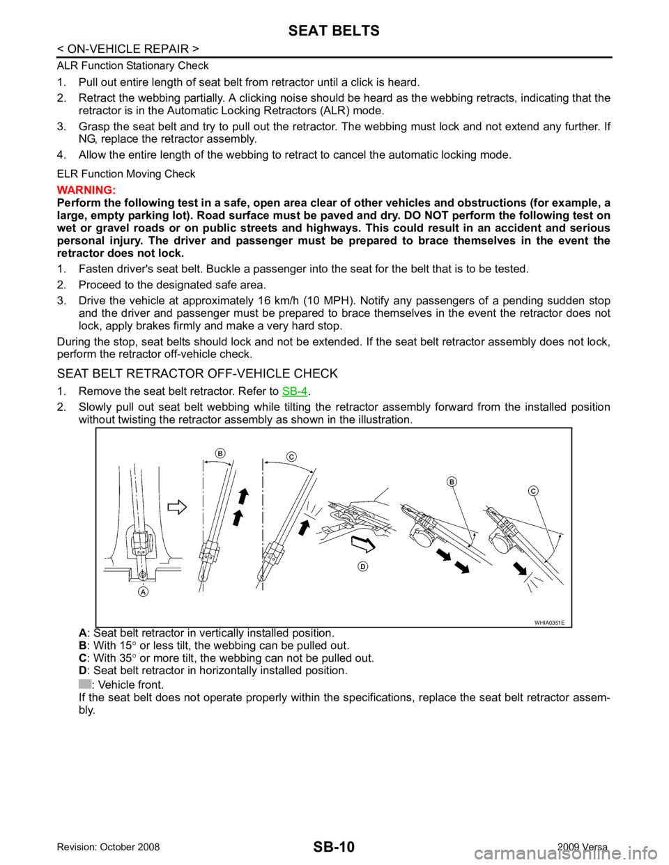
.
2. Slowly pull out seat belt webbing while tilting the re tractor assembly forward from the installed position
without twisting the retractor assemb ly as shown in the illustration.
A : Seat belt retractor in ve rtically installed position.
B : With 15 ° or less tilt, the webbing can be pulled out.
C : With 35 ° or more tilt, the webbing can not be pulled out.
D : Seat belt retractor in horizontally installed position.
: Vehicle front.
If the seat belt does not operate properly within the s pecifications, replace the seat belt retractor assem-
bly.
Page 4135 of 4331
SB
N
O P
LATCH (LOWER ANCHORS AND TE
THER FOR CHILDREN) SYSTEM
Removal and Installation INFOID:0000000004307385
NOTE:
The LATCH (Lower Anchors and Tether fo r Children) system is not serviceable.
Page 4136 of 4331
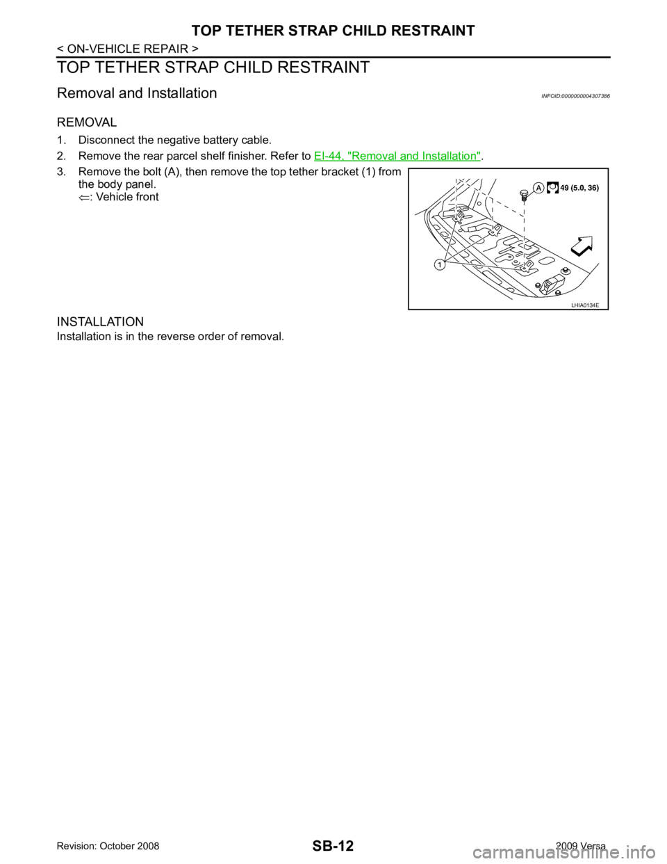
Removal and Installation " .
3. Remove the bolt (A), then remove the top tether bracket (1) from the body panel.
⇐ : Vehicle front
INSTALLATION
Installation is in the reverse order of removal.
Page 4137 of 4331
SC
N
O P
CONTENTS
STARTING & CHARGING SYSTEM
SERVICE INFORMATION .. ..........................2
PRECAUTIONS .............................................. .....2
Precaution for Supplemental Restraint System
(SRS) "AIR BAG" and "SEAT BELT PRE-TEN-
SIONER" ............................................................. ......
2
Precaution Necessary fo r Steering Wheel Rota-
tion After Battery Disconnect ............................... ......
2
PREPARATION .............................................. .....4
Special Service Tool ........................................... ......4
Commercial Service Tool .................................... ......4
BATTERY ....................................................... .....5
How to Handle Ba ttery ........................................ ......5
Trouble Diagnosis with Battery Service Center ... ......7
Removal and Installation ...........................................7
Required Procedure After Battery Disconnection ......8
STARTING SYSTEM ...................................... .....9 System Description ..............................................
.....9
Wiring Diagram - START - ................................... ....11
Trouble Diagnosis with Multitasking Battery Diag-
nostic Station ....................................................... ....
16
Removal and Installation HR16DE ...................... ....19
Removal and Installation MR18DE ...................... ....20
CHARGING SYSTEM ....................................... 21
System Description .............................................. ....21
Wiring Diagram - CHARGE - ............................... ....22
Trouble Diagnosis with Multitasking Battery Diag-
nostic Station ....................................................... ....
22
Removal and Installation ..................................... ....25
SERVICE DATA AND SPECIFICATIONS
(SDS) ................................................................. 27
Battery ................................................................. ....27
Starter .................................................................. ....27
Generator ............................................................ ....27
Page 4138 of 4331
Page 4139 of 4331
SC
N
O P
5. When the repair work is completed, return the ignition switch to the
″LOCK ″ position before connecting
the battery cables. (At this time, the steering lock mechanism will engage.)
6. Perform a self-diagnosis check of al l control units using CONSULT-III.
Page 4140 of 4331
