NISSAN TIIDA 2009 Service Repair Manual
Manufacturer: NISSAN, Model Year: 2009, Model line: TIIDA, Model: NISSAN TIIDA 2009Pages: 4331, PDF Size: 58.04 MB
Page 4121 of 4331
Page 4122 of 4331
COIL SPRING
RSU-11
< SERVICE INFORMATION >
C
D
F
G H
I
J
K L
M A
B RSU
N
O P
COIL SPRING
Removal and Installation INFOID:0000000004305882
REMOVAL 1. Remove wheel and tire using power tool.
2. Remove wheel sensor from wheel hub and bearing assembly. Refer to BRC-32, " Removal and Installa-
tion " .
CAUTION:
Do not pull on wheel sensor harness.
3. Separate brake tube from wheel cylinder. Refer to BR-12, " Rear Brake Tube and Hose " .
4. Set jack under rear suspension beam.
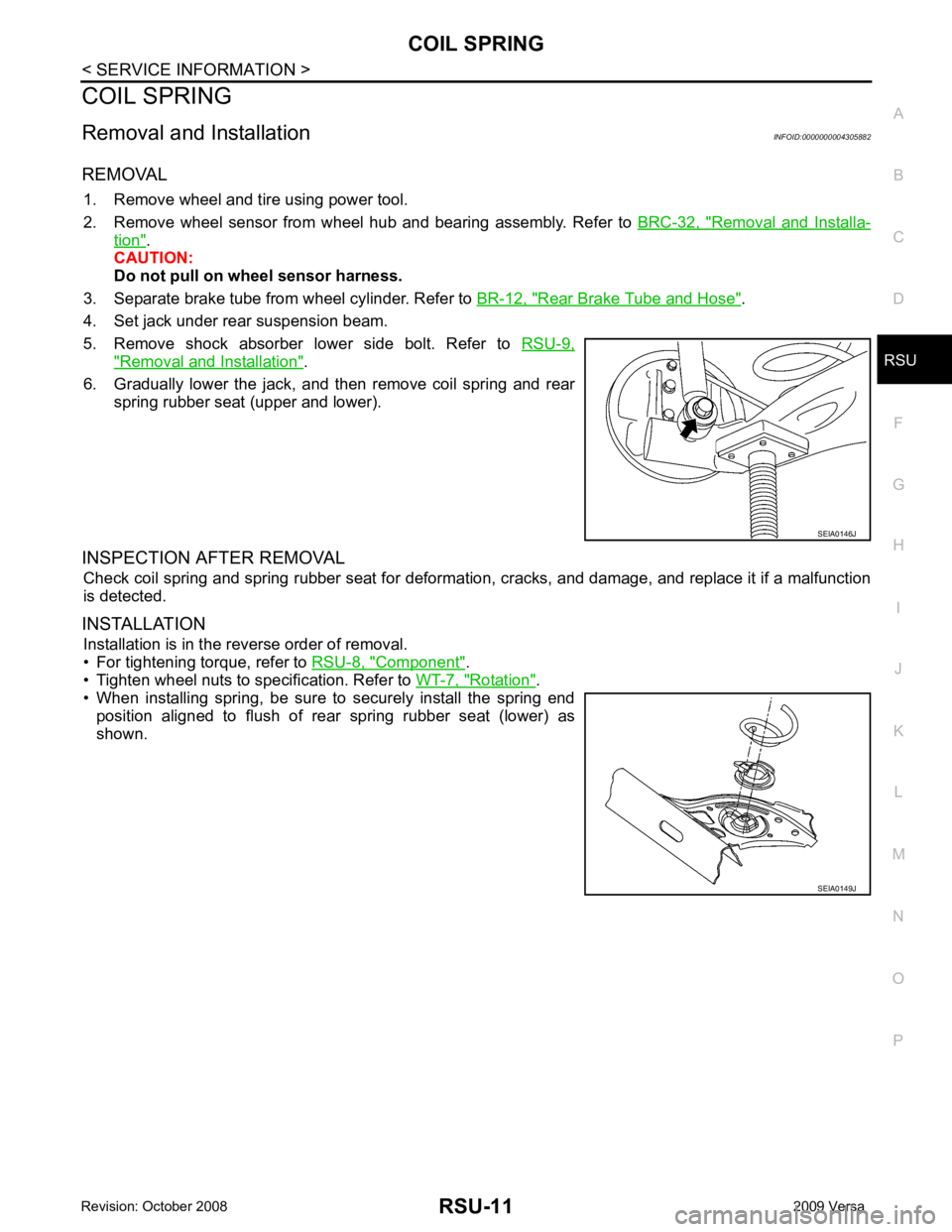
5. Remove shock absorber lower side bolt. Refer to RSU-9," Removal and Installation " .
6. Gradually lower the jack, and then remove coil spring and rear spring rubber seat (upper and lower).
INSPECTION AFTER REMOVAL Check coil spring and spring rubber seat for deformation, cracks, and damage, and replace it if a malfunction
is detected.
INSTALLATION Installation is in the reverse order of removal.
• For tightening torque, refer to RSU-8, " Component " .
• Tighten wheel nuts to specification. Refer to WT-7, " Rotation " .
• When installing spring, be sure to securely install the spring end
position aligned to flush of rear spring rubber seat (lower) as
shown. SEIA0146J
SEIA0149J
Page 4123 of 4331
On-
Vehicle Service " .
3. Remove wheel sensor and wheel sensor harness from wheel hub and bearing assembly and rear suspen-
sion beam. Refer to BRC-32, " Removal and Installation " .
4. Remove lock plate and separate brake tube from brake hose. Refer to BR-12, " Rear Brake Tube and Hose " .
5. Remove wheel hub and bearing assembly and back plate. Refer to RAX-5, " On-Vehicle Inspection and Service " .
6. Set jack under rear suspension beam.
7. Remove coil spring (left/right). Refer to RSU-11, " Removal and
Installation " .
8. Remove bolts between body and rear suspension beam bracket. Refer to RSU-8, " Component " .
9. Gradually lower the jack, and then remove rear suspension beam from vehicle.
10. Remove the rear suspension beam bracket bolt and nut, and then remove rear suspension beam bracket
from rear suspension beam. Refer to RSU-8, " Component " .
11. Remove brake tube protector from rear suspension beam.
INSPECTION AFTER REMOVAL
Check components for deformation, cracks, and other damage, and replace if necessary.
INSTALLATION
Installation is in the reverse order of removal.
• For tightening torque, refer to RSU-8, " Component " .
• Refill with new brake fluid and bleed air. Refer to BR-9, " Bleeding Brake System " .
• Tighten wheel nuts to specification. Refer to WT-7, " Rotation " .
• Check the following after finishing work.
- Parking brake operation (stroke): Refer to PB-5, " On-Vehicle Service " .
- Wheel sensor harness for proper connection: Refer to BRC-32, " Removal and Installation " .
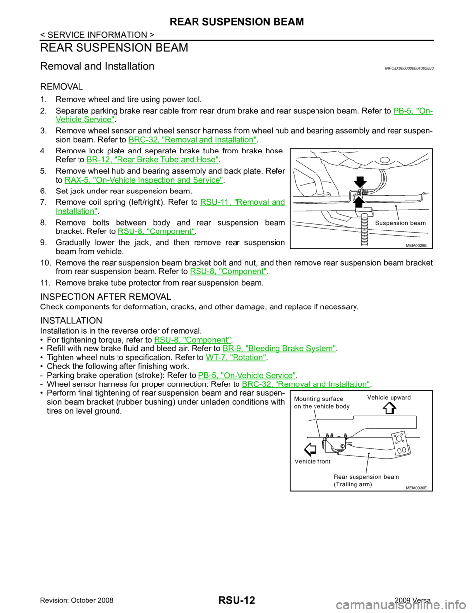
• Perform final tightening of rear suspension beam and rear suspen-
sion beam bracket (rubber bushing) under unladen conditions with
tires on level ground. MEIA0030E
Page 4124 of 4331
RSU
N
O P
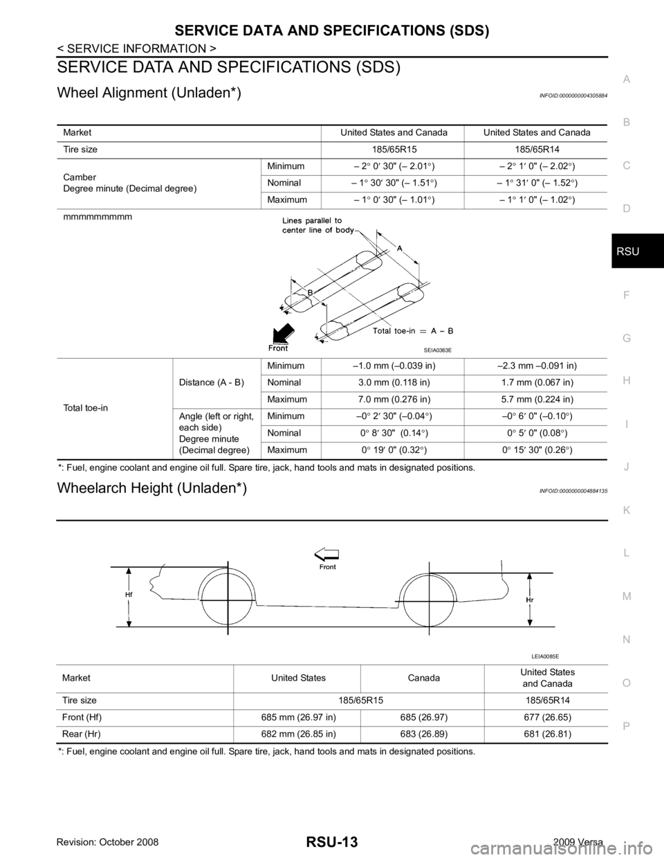
SERVICE DATA AND SPECIFICATIONS (SDS)
Wheel Alignment (Unladen*) INFOID:0000000004305884
*: Fuel, engine coolant and engine oil full. Spare tire, jack, hand tools and mats in designated positions.
Wheelarch Height (Unladen*) INFOID:0000000004884135
*: Fuel, engine coolant and engine oil full. Spare tire, jack, hand tools and mats in designated positions. Market United States and Canada United States and Canada
Tire size 185/65R15 185/65R14
Camber
Degree minute (Decimal degree) Minimum – 2
° 0 ′ 30" (– 2.01 °) – 2 ° 1 ′ 0" (– 2.02 °)
Nominal – 1 ° 30 ′ 30" (– 1.51 °) – 1 ° 31 ′ 0" (– 1.52 °)
Maximum – 1 ° 0 ′ 30" (– 1.01 °) – 1 ° 1 ′ 0" (– 1.02 °)
mmmmmmmmm
Total toe-in Distance (A - B)
Minimum –1.0 mm (–0.039 in) –2.3 mm –0.091 in)
Nominal 3.0 mm (0.118 in) 1.7 mm (0.067 in)
Maximum 7.0 mm (0.276 in) 5.7 mm (0.224 in)
Angle (left or right,
each side)
Degree minute
(Decimal degree) Minimum –0
° 2 ′ 30" (–0.04 °) –0 ° 6 ′ 0" (–0.10 °)
Nominal 0 ° 8 ′ 30" (0.14 °) 0 ° 5 ′ 0" (0.08 °)
Maximum 0 ° 19 ′ 0" (0.32 °) 0 ° 15 ′ 30" (0.26 °)
Page 4125 of 4331
SB
N
O P
CONTENTS
SEAT BELTS
PRECAUTION ....... ........................................2
PRECAUTIONS .............................................. .....2
Precaution for Supplemental Restraint System
(SRS) "AIR BAG" and "SEAT BELT PRE-TEN-
SIONER" ............................................................. ......
2
Precaution Necessary fo r Steering Wheel Rota-
tion After Battery Disconnect ............................... ......
2
Precaution for Seat Belt Service ......................... ......2
ON-VEHICLE REPAIR .... ..............................4 SEAT BELTS .....................................................
4
Removal and Installation of Front Seat Belt ........ .....4
Removal and Installation of Rear Seat Belt ..............6
Seat Belt Inspection ............................................. .....8
LATCH (LOWER ANCHORS AND TETHER
FOR CHILDREN) SYSTEM ............................... 11
Removal and Installation ..................................... ....11
TOP TETHER STRAP CHILD RESTRAINT ..... 12
Removal and Installation ..................................... ....12
Page 4126 of 4331
Page 4127 of 4331
SB
N
O P
• After replacing or reinstalling front seat belt
pre-tensioner assembly, or reconnecting front seat belt
pre-tensioner connector, check th e system function. Refer to SRS-19, " SRS Operation Check " .
• Do not disassemble buckle or seat belt assembly.
• Do not reuse seat belt anchor bolts after removal. Replace with new ones.
• Replace anchor bolts if th ey are deformed or worn out.
• Never oil tongue and buckle.
• If any component of seat belt assembly is questio nable, do not repair. Replace the whole seat belt
assembly.
• If webbing is cut, frayed, or damaged, replace seat belt assembly.
• When replacing seat belt assembly, u se a genuine NISSAN seat belt assembly.
AFTER A COLLISION WARNING:
• Inspect all seat belt assemblies including retractors and attaching hardware after any collision.
• NISSAN recommends that all seat belt assemblies in use during a collision be replaced unless the
collision was minor and the belts show no damage and continue to operate properly. Failure to do so
could result in serious personal injury in an acci dent. Seat belt assemblies not in use during a colli-
sion should also be replaced if either damage or im proper operation is noted. Seat belt pre-tensioner
should be replaced even if the seat belts are not in use during a frontal collision in which the air bags
are deployed.
Replace any seat belt assembly (including anchor bolts) if:
• The seat belt was in use at the time of a collision (except for minor collisions and the belts, retractors and
buckles show no damage and continue to operate properly).
• The seat belt was damaged in an accident. (i.e. torn webbing, bent retractor or guide).
• The seat belt attaching point was damaged in an accident. Inspect the seat belt attaching area for damage or distortion and repair as necessary before installing a new seat belt assembly.
• Anchor bolts are deformed or worn out.
• The seat belt pre-tensioner should be replaced even if t he seat belts are not in use during the collision in
which the air bags are deployed.
Page 4128 of 4331
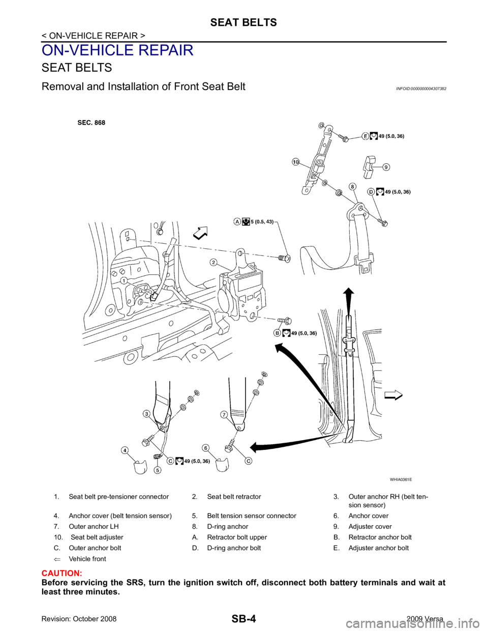
Page 4129 of 4331
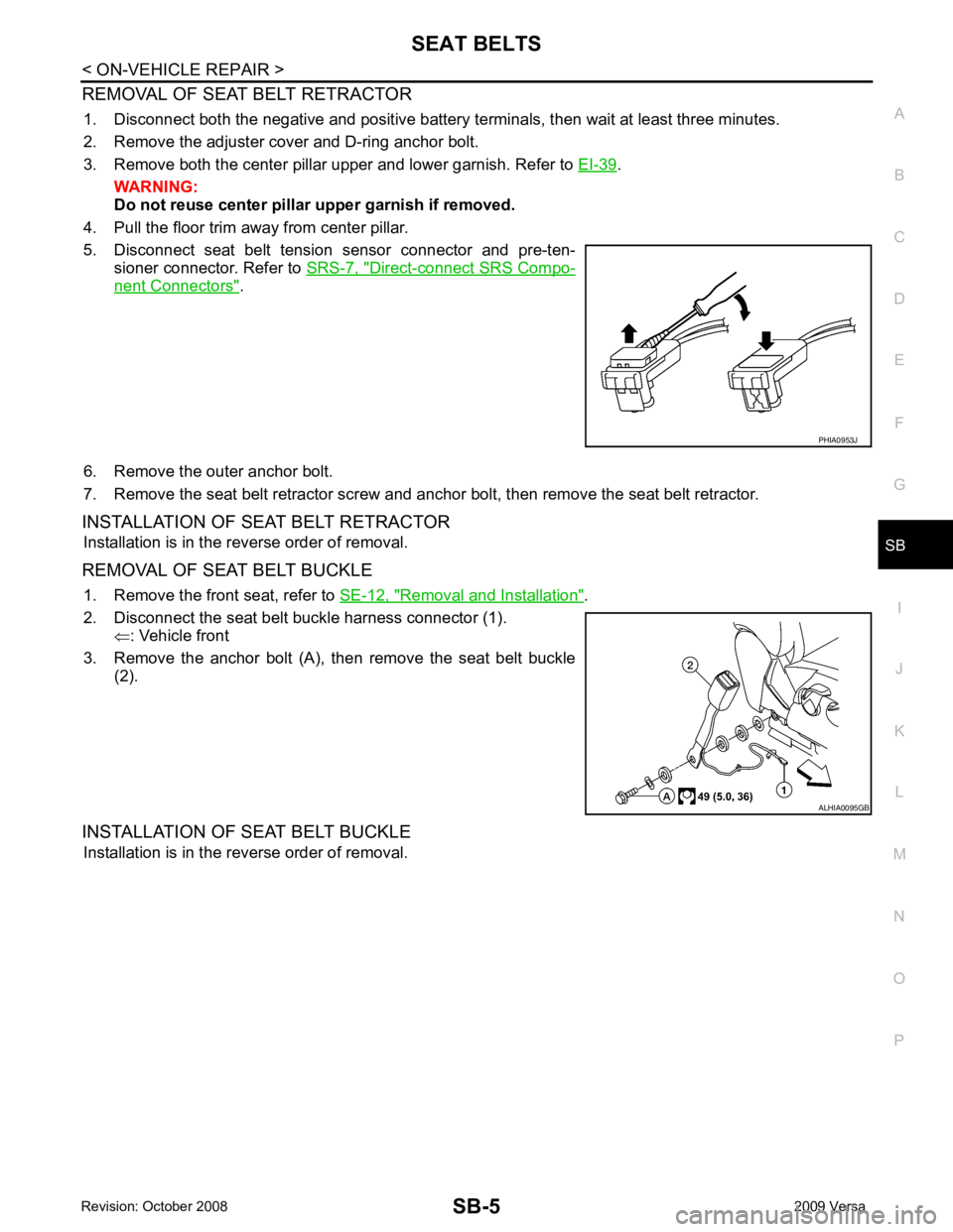
SB
N
O P
REMOVAL OF SEAT BELT RETRACTOR
1. Disconnect both the negative and positive battery te rminals, then wait at least three minutes.
2. Remove the adjuster cover and D-ring anchor bolt.
3. Remove both the center pillar upper and lower garnish. Refer to EI-39 .
WARNING:
Do not reuse center pillar upper garnish if removed.
4. Pull the floor trim away from center pillar.
5. Disconnect seat belt tension sensor connector and pre-ten- sioner connector. Refer to SRS-7, " Direct-connect SRS Compo-
nent Connectors " .
6. Remove the outer anchor bolt.
7. Remove the seat belt retractor screw and anchor bolt, then remove the seat belt retractor.
INSTALLATION OF SEAT BELT RETRACTOR Installation is in the reverse order of removal.
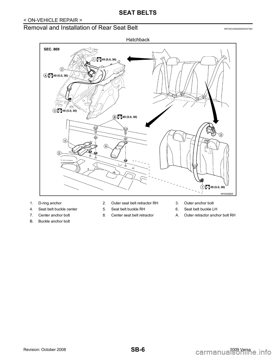
REMOVAL OF SEAT BELT BUCKLE 1. Remove the front seat, refer to SE-12, " Removal and Installation " .
2. Disconnect the seat belt buckle harness connector (1). ⇐: Vehicle front
3. Remove the anchor bolt (A), then remove the seat belt buckle (2).
INSTALLATION OF SEAT BELT BUCKLE Installation is in the reverse order of removal.
Page 4130 of 4331
