NISSAN TIIDA 2009 Service Repair Manual
TIIDA 2009
NISSAN
NISSAN
https://www.carmanualsonline.info/img/5/57398/w960_57398-0.png
NISSAN TIIDA 2009 Service Repair Manual
Trending: fuel cap, Airbag module, Side marker, ABS, drum brakes, front bumper removal and installation, Dryer
Page 451 of 4331
Page 452 of 4331
Page 453 of 4331
BCS
N
O P
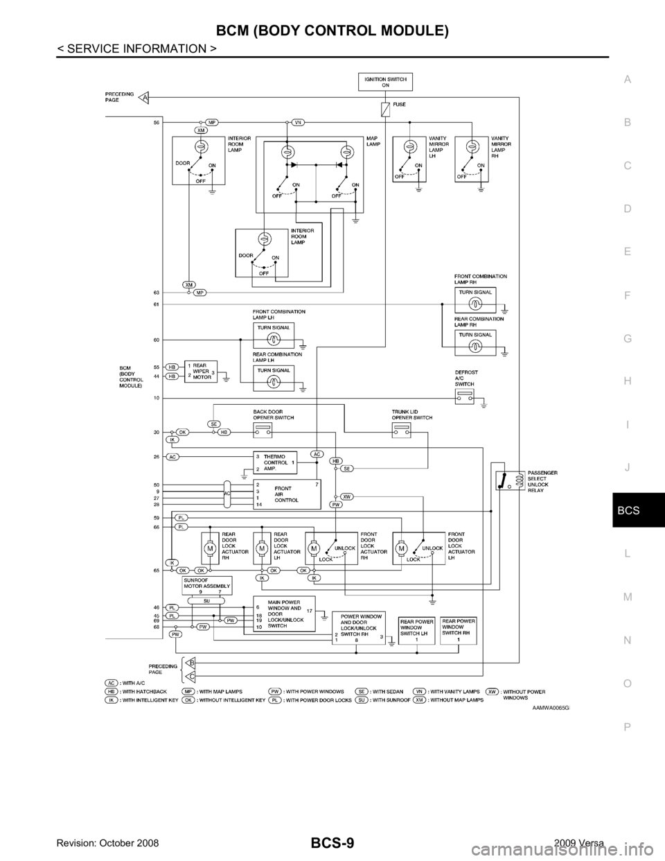
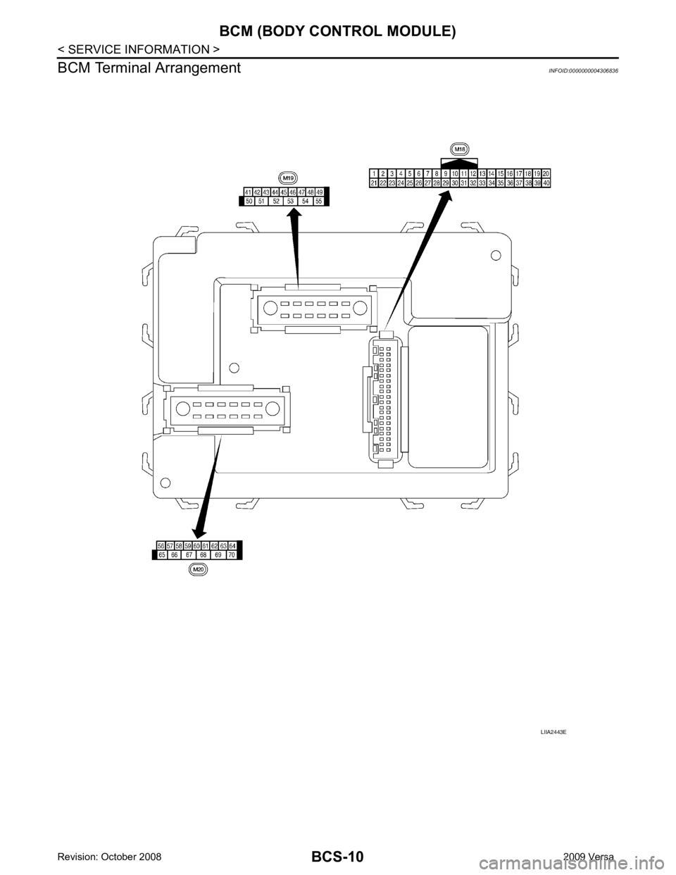
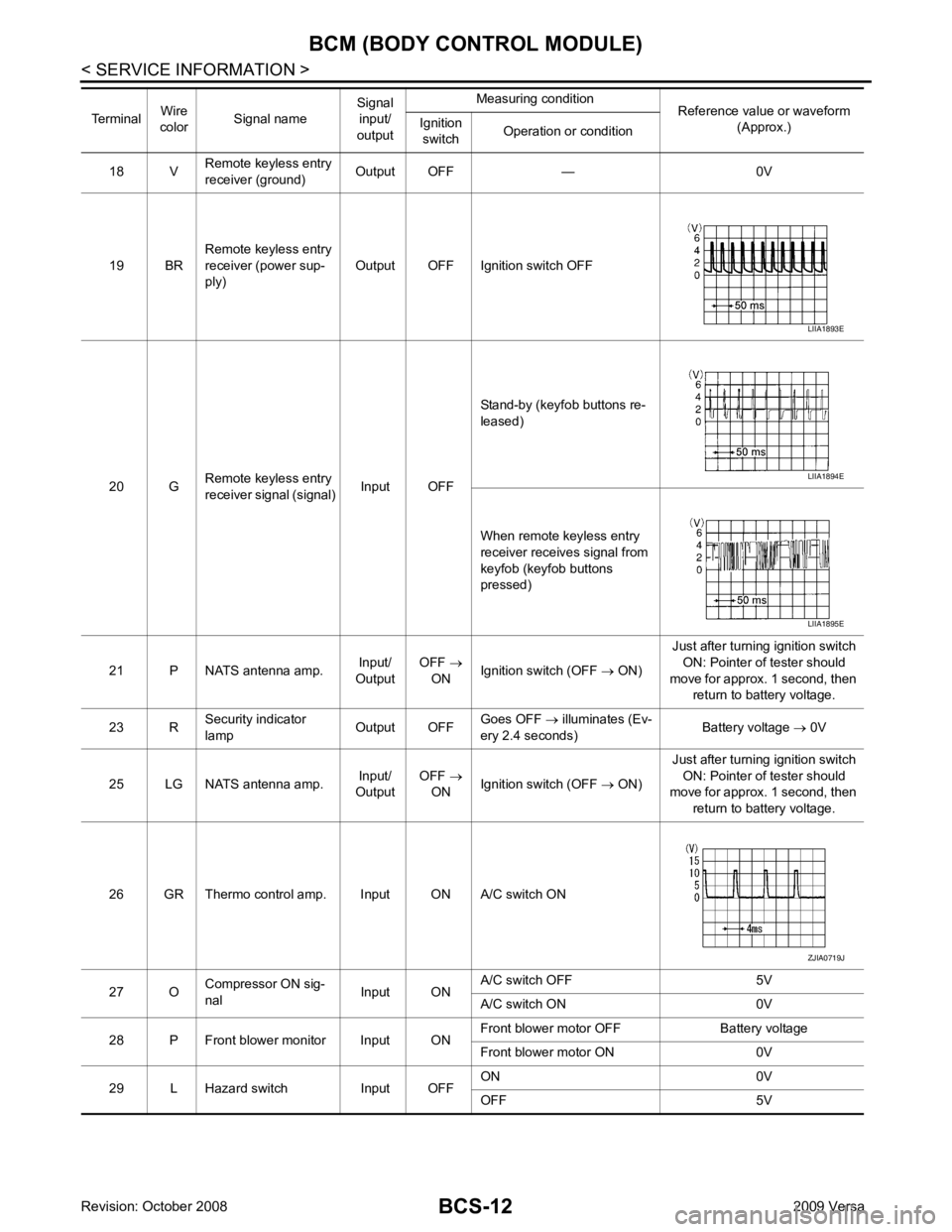
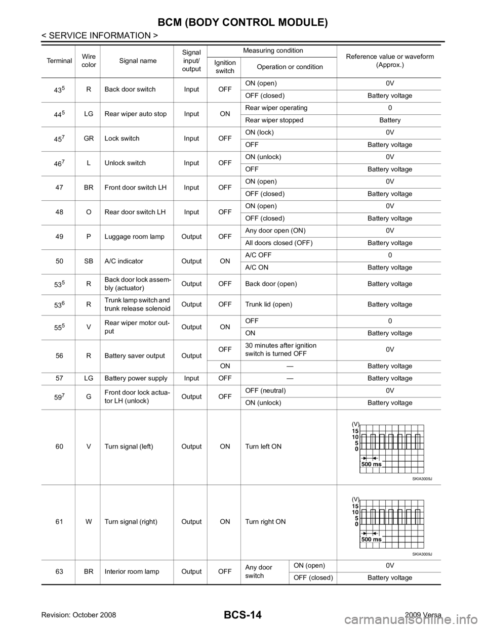
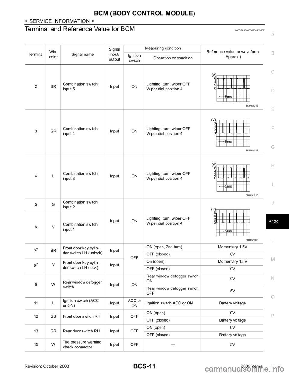
Terminal and Reference Value for BCM
INFOID:0000000004306837
Terminal Wire
color Signal name Signal
input/
output Measuring condition
Reference value or waveform
(Approx.)
Ignition
switch Operation or condition
2 BR Combination switch
input 5 Input ONLighting, turn, wiper OFF
Wiper dial position 4
3 GR Combination switch
input 4 Input ONLighting, turn, wiper OFF
Wiper dial position 4
4 L Combination switch
input 3 Input ONLighting, turn, wiper OFF
Wiper dial position 4
5 G Combination switch
input 2
Input ONLighting, turn, wiper OFF
Wiper dial position 4
6 V Combination switch
input 1
7 7
BRFront door key cylin-
der switch LH (unlock) Input
OFFON (open, 2nd turn) Momentary 1.5V
OFF (closed) 0V
8 7
YFront door key cylin-
der switch LH (lock) InputOn (open) Momentary 1.5V
OFF (closed) 0V
9 W Rear window defogger
switch Input ONRear window defogger switch
ON 0V
Rear window defogger switch
OFF 5V
11 L Ignition switch (ACC
or ON) InputACC or
ON Ignition switch ACC or ON Battery voltage
12 SB Front door switch RH Input OFF ON (open) 0V
OFF (closed) Battery voltage
13 GR Rear door switch RH Input OFF ON (open) 0V
OFF (closed) Battery voltage
15 W Tire pressure warning
check connector Input OFF — 5V
Page 454 of 4331
Page 455 of 4331
BCM (BODY CONTROL MODULE)
BCS-13
< SERVICE INFORMATION >
C
D E
F
G H
I
J
L
M A
B BCS
N
O P
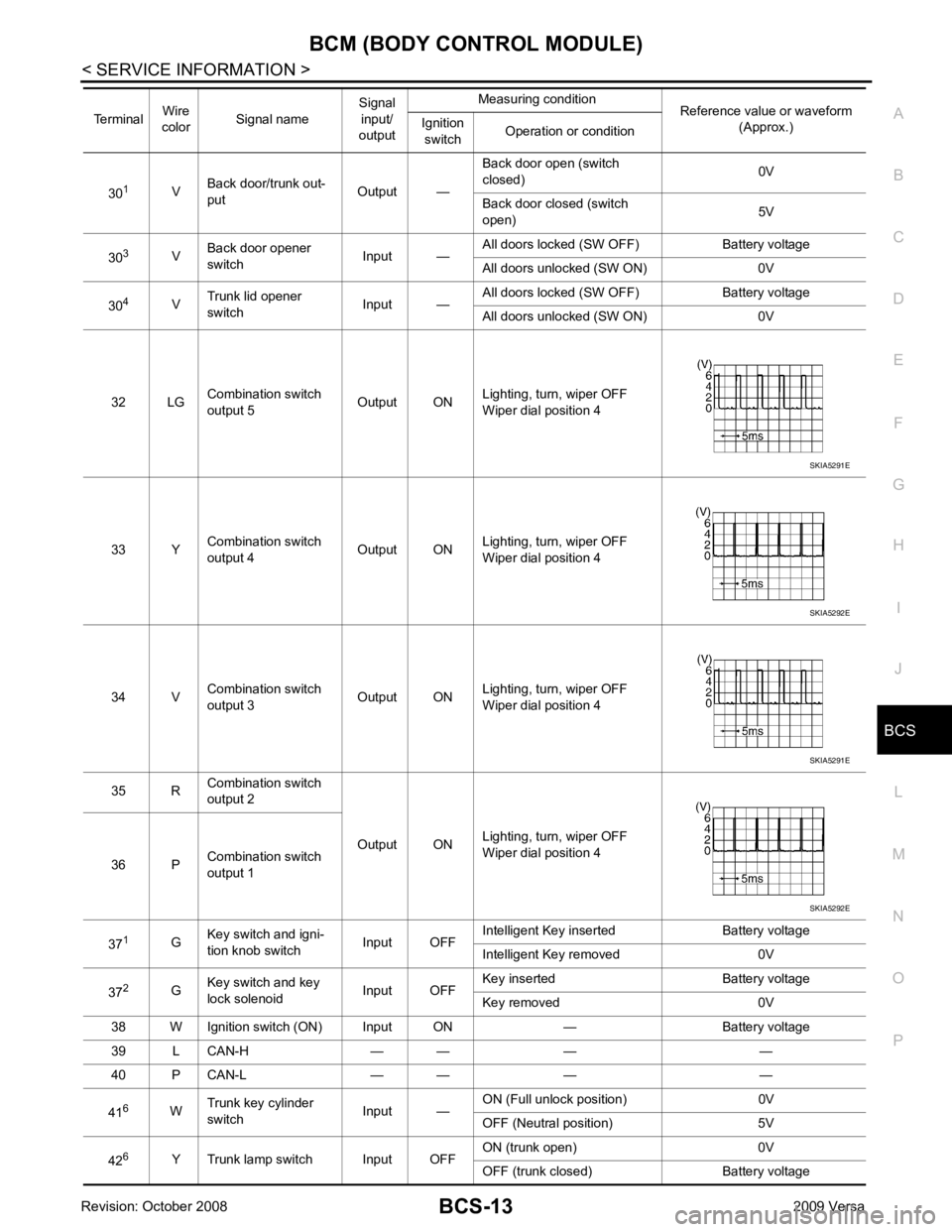
30
1
VBack door/trunk out-
put Output —Back door open (switch
closed) 0V
Back door closed (switch
open) 5V
30 3
VBack door opener
switch Input —All doors locked (SW OFF) Battery voltage
All doors unlocked (SW ON) 0V
30 4
VTrunk lid opener
switch Input —All doors locked (SW OFF) Battery voltage
All doors unlocked (SW ON) 0V
32 LG Combination switch
output 5 Output ONLighting, turn, wiper OFF
Wiper dial position 4
33 Y Combination switch
output 4 Output ON
Lighting, turn, wiper OFF
Wiper dial position 4
34 V Combination switch
output 3 Output ONLighting, turn, wiper OFF
Wiper dial position 4
35 R Combination switch
output 2
Output ONLighting, turn, wiper OFF
Wiper dial position 4
36 P Combination switch
output 1
37 1
GKey switch and igni-
tion knob switch Input OFFIntelligent Key inserted Battery voltage
Intelligent Key removed 0V
37 2
GKey switch and key
lock solenoid Input OFFKey inserted Battery voltage
Key removed 0V
38 W Ignition switch (ON) Input ON — Battery voltage
39 L CAN-H — — — —
40 P CAN-L — — — —
41 6
WTrunk key cylinder
switch Input —ON (Full unlock position) 0V
OFF (Neutral position) 5V
42 6
Y Trunk lamp switch Input OFF ON (trunk open) 0V
OFF (trunk closed) Battery voltage
Terminal
Wire
color Signal name Signal
input/
output Measuring condition
Reference value or waveform
(Approx.)
Ignition
switch Operation or condition SKIA5291E
SKIA5292E
SKIA5291E
SKIA5292E
Page 456 of 4331
Page 457 of 4331
BCS
N
O P
1: With Intelligent Key
2: Without Intelligent Key
3: Hatchback without Intelligent Key
4: Sedan without Intelligent Key
5: Hatchback
6: Sedan
7: With power door locks
8: With power windows
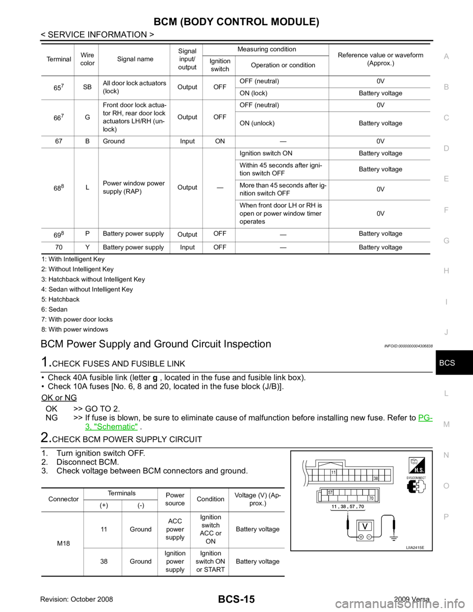
BCM Power Supply and Gr ound Circuit Inspection INFOID:0000000004306838OK >> GO TO 2.
NG >> If fuse is blown, be sure to eliminate caus e of malfunction before installing new fuse. Refer to PG-3, " Schematic " .
Connector
Terminals
Power
source Condition Voltage (V) (Ap-
prox.)
(+) (-)
M18 11 Ground
ACC
power
supply Ignition
switch
ACC or
ON Battery voltage
38 Ground Ignition
power
supply Ignition
switch ON or START Battery voltage
Page 458 of 4331
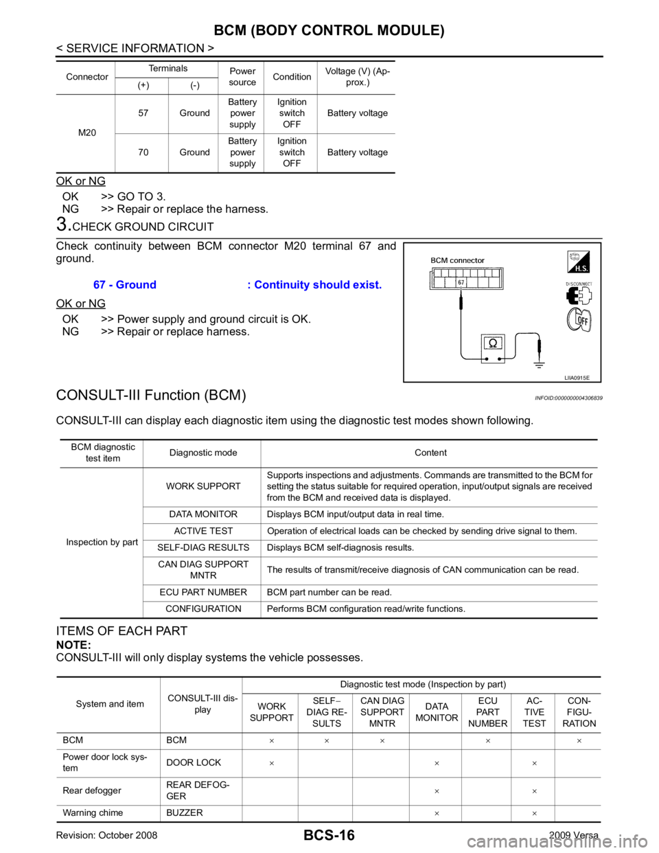
OK >> GO TO 3.
NG >> Repair or replace the harness. OK >> Power supply and ground circuit is OK.
NG >> Repair or replace harness.
CONSULT-III Function (BCM) INFOID:0000000004306839
CONSULT-III can display each diagnostic item us ing the diagnostic test modes shown following.
ITEMS OF EACH PART
NOTE:
CONSULT-III will only display systems the vehicle possesses. M20
57 Ground
Battery
power
supply Ignition
switch
OFF Battery voltage
70 Ground Battery
power
supply Ignition
switch OFF Battery voltage
Connector
Terminals
Power
source Condition Voltage (V) (Ap-
prox.)
(+) (-) System and item
CONSULT-III dis-
play Diagnostic test mode (Inspection by part)
WORK
SUPPORT SELF
−
DIAG RE- SULTS CAN DIAG
SUPPORT MNTR DATA
MONITOR ECU
PART
NUMBER AC-
TIVE
TEST CON-
FIGU-
RATION
BCM BCM × × × × ×
Power door lock sys-
tem DOOR LOCK
× × ×
Rear defogger REAR DEFOG-
GER × ×
Warning chime BUZZER × ×
Page 459 of 4331
BCS
N
O P
WORK SUPPORT
Display Item List
CAN Communication Inspection Usin g CONSULT-III (Self-Diagnosis) INFOID:0000000004306840Item Description
RESET SETTING VALUE Return a value set with WORK SUPPORT of each system to a default value in factory shipment. CONSULT-III display code Diagnosis item
U1000 INITIAL DIAG
TRANSMIT DIAG ECM
IPDM E/R
METER/M&A I-KEY
Page 460 of 4331
Trouble Diagnosis Flow Chart " .
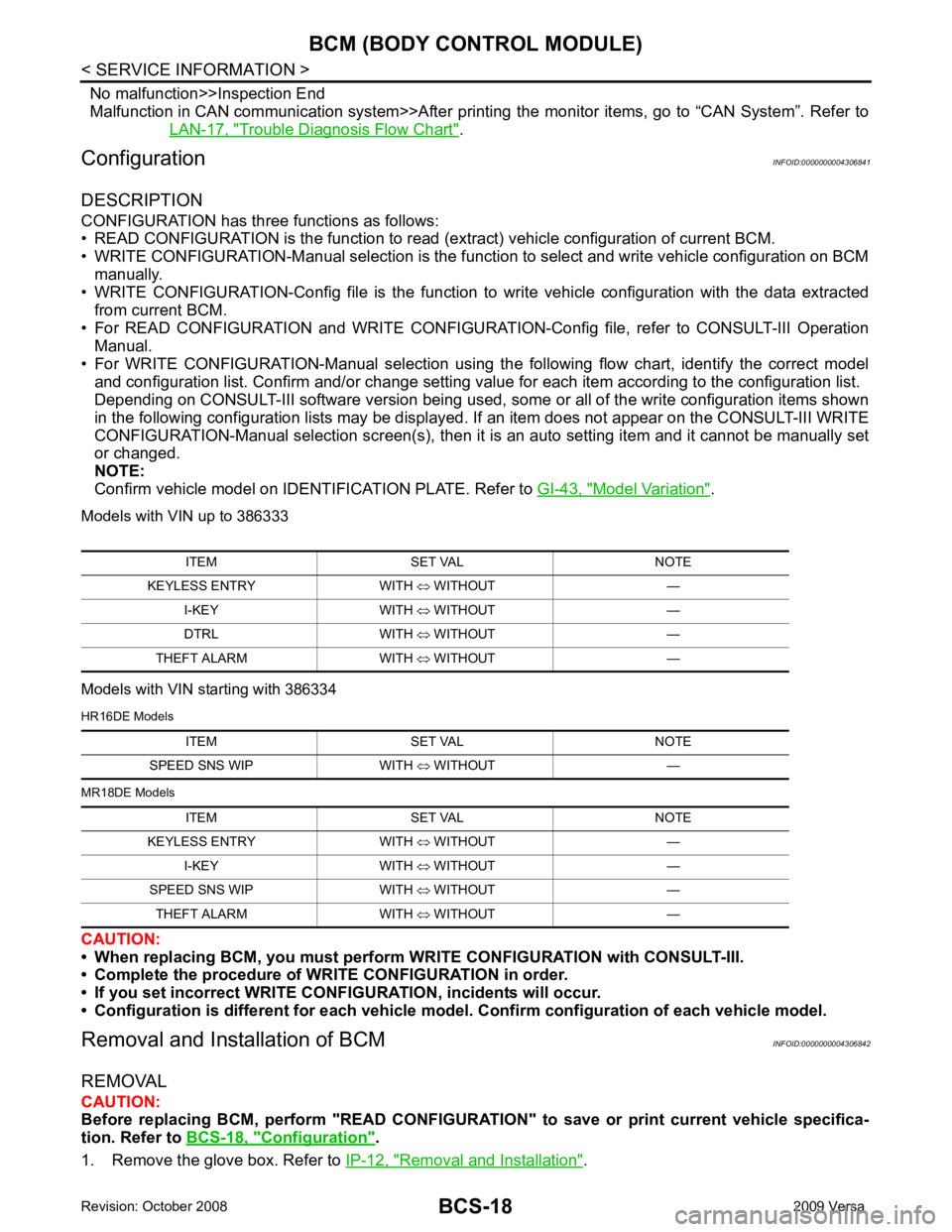
Configuration INFOID:0000000004306841
DESCRIPTION
CONFIGURATION has three functions as follows:
• READ CONFIGURATION is the function to read (e xtract) vehicle configuration of current BCM.
• WRITE CONFIGURATION-Manual selection is the functi on to select and write vehicle configuration on BCM
manually.
• WRITE CONFIGURATION-Config file is the function to write vehicle configuration with the data extracted
from current BCM.
• For READ CONFIGURATION and WRIT E CONFIGURATION-Config file, refer to CONSULT-III Operation
Manual.
• For WRITE CONFIGURATION-Manual selection using the following flow chart, identify the correct model
and configuration list. Confirm and/or change setting value for each item according to the configuration list.
Depending on CONSULT-III software version being used, some or all of the write configuration items shown
in the following configuration lists may be displayed. If an item does not appear on the CONSULT-III WRITE
CONFIGURATION-Manual selection screen(s), then it is an auto setting item and it cannot be manually set
or changed.
NOTE:
Confirm vehicle model on IDENTI FICATION PLATE. Refer to GI-43, " Model Variation " .
Models with VIN up to 386333
Models with VIN starting with 386334
HR16DE Models
MR18DE Models
CAUTION:
• When replacing BCM, you must perform WRITE CONFIGURATION with CONSULT-III.
• Complete the procedure of WRITE CONFIGURATION in order.
• If you set incorrect WRITE CONF IGURATION, incidents will occur.
• Configuration is different for each vehicle mode l. Confirm configuration of each vehicle model.
Removal and Installation of BCM INFOID:0000000004306842
REMOVAL
CAUTION:
Before replacing BCM, perform "READ CONFIGURATI ON" to save or print current vehicle specifica-
tion. Refer to BCS-18, " Configuration " .
1. Remove the glove box. Refer to IP-12, " Removal and Installation " .
ITEM SET VAL NOTE
KEYLESS ENTRY WITH ⇔ WITHOUT —
I-KEY WITH ⇔ WITHOUT —
DTRL WITH ⇔ WITHOUT —
THEFT ALARM WITH ⇔ WITHOUT — ITEM SET VAL NOTE
SPEED SNS WIP WITH ⇔ WITHOUT —
ITEM SET VAL NOTE
KEYLESS ENTRY WITH ⇔ WITHOUT —
I-KEY WITH ⇔ WITHOUT —
SPEED SNS WIP WITH ⇔ WITHOUT —
THEFT ALARM WITH ⇔ WITHOUT —
Trending: ecu connector, roof, electrical diagram, power window system, open gas tank, height, break
