NISSAN TIIDA 2010 Service Repair Manual
Manufacturer: NISSAN, Model Year: 2010, Model line: TIIDA, Model: NISSAN TIIDA 2010Pages: 3745, PDF Size: 73.67 MB
Page 3491 of 3745
SQUEAK AND RATTLE TROUBLE DIAGNOSESRF-7
< SYMPTOM DIAGNOSIS >
C
DE
F
G H
J
K L
M A
B
RF
N
O P
The following materials, not available through NISSAN Parts Department, can also be used to repair squeaks
and rattles.
UHMW(TEFLON) TAPE
Insulates where slight movement is present. Ideal for instrument panel applications.
SILICONE GREASE
Used in place of UHMW tape that will be visible or not fit.
Note: Will only last a few months.
SILICONE SPRAY
Use when grease cannot be applied.
DUCT TAPE
Use to eliminate movement.
CONFIRM THE REPAIR
Confirm that the cause of a noise is repaired by test driving the vehicle. Operate the vehicle under the same
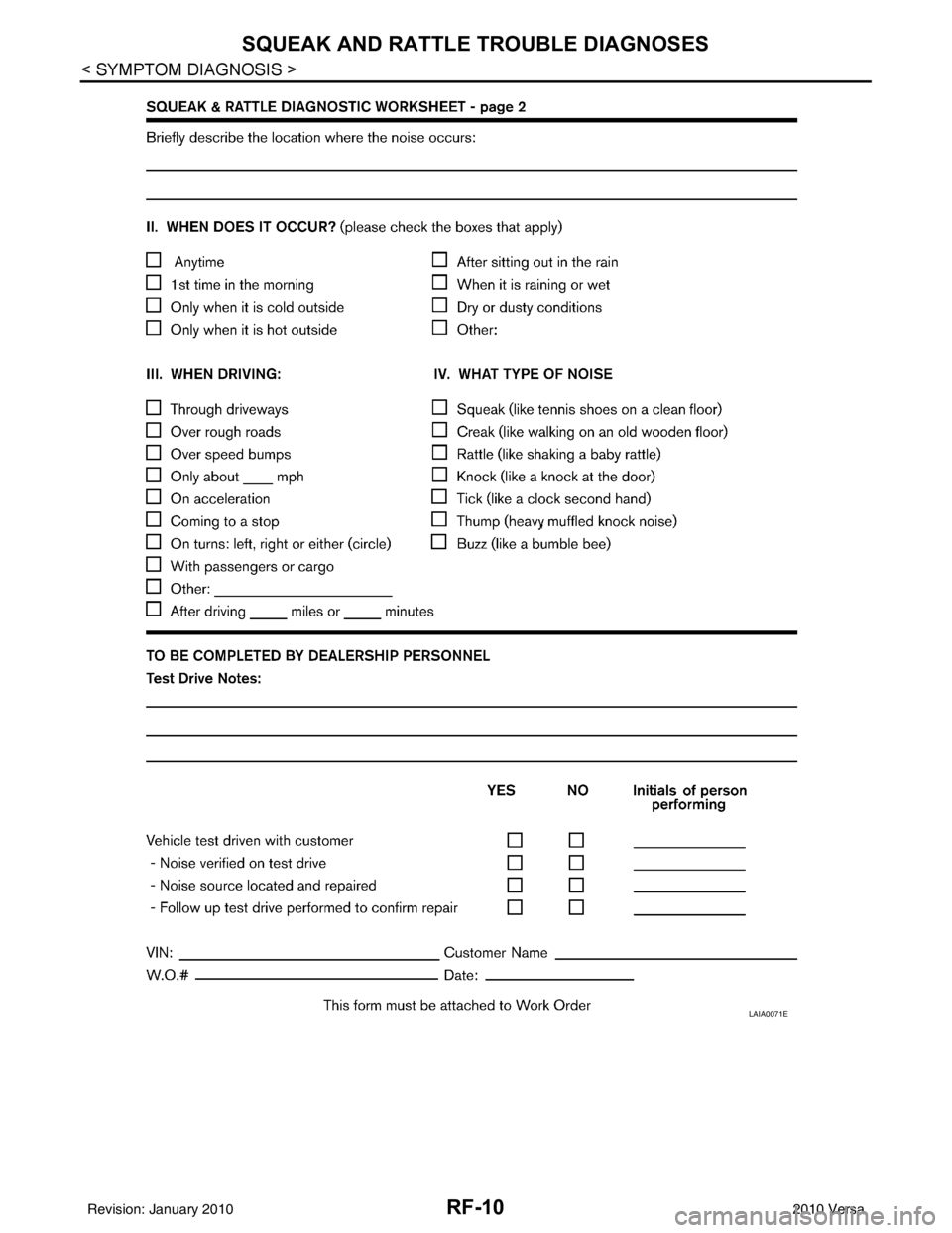
conditions as when the noise originally occurred. Refer to the notes on the Diagnostic Worksheet.
Generic Squeak and Rattle TroubleshootingINFOID:0000000005396792
Refer to Table of Contents for specific component removal and installation information.
INSTRUMENT PANEL
Most incidents are caused by contact and movement between:
1. The cluster lid A and instrument panel
2. Acrylic lens and combination meter housing
3. Instrument panel to front pillar garnish
4. Instrument panel to windshield
5. Instrument panel pins
6. Wiring harnesses behind the combination meter
7. A/C defroster duct and duct joint
These incidents can usually be located by tapping or moving the components to duplicate the noise or by
pressing on the components while driving to stop the noi se. Most of these incidents can be repaired by apply-
ing felt cloth tape or silicone spray (in hard to reach areas). Urethane pads can be used to insulate wiring har-
ness.
CAUTION:
Do not use silicone spray to isolate a squeak or ra ttle. If you saturate the area with silicone, you will
not be able to recheck the repair.
CENTER CONSOLE
Components to pay attention to include:
1. Shifter assembly cover to finisher
2. A/C control unit and cluster lid C
3. Wiring harnesses behind audio and A/C control unit
The instrument panel repair and isolation pr ocedures also apply to the center console.
DOORS
Pay attention to the:
1. Finisher and inner panel making a slapping noise
2. Inside handle escutcheon to door finisher
3. Wiring harnesses tapping
4. Door striker out of alignment causing a popping noise on starts and stops
Tapping or moving the components or pressing on them while driving to duplicate the conditions can isolate
many of these incidents. You can usually insulate the ar eas with felt cloth tape or insulator foam blocks from
the NISSAN Squeak and Rattle Kit (J-43980) to repair the noise.
TRUNK
Trunk noises are often caused by a loose jack or loose items put into the trunk by the owner.
In addition look for:
1. Trunk lid bumpers out of adjustment
Revision: January 20102010 Versa
Page 3492 of 3745

RF-8
< SYMPTOM DIAGNOSIS >
SQUEAK AND RATTLE TROUBLE DIAGNOSES
2. Trunk lid striker out of adjustment
3. The trunk lid torsion bars knocking together
4. A loose license plate or bracket
Most of these incidents can be repaired by adjusting, securing or insulating the item(s) or component(s) caus-
ing the noise.
SUNROOF/HEADLINING
Noises in the sunroof/headlining area c an often be traced to one of the following:
1. Sunroof lid, rail, linkage or seals making a rattle or light knocking noise
2. Sun visor shaft shaking in the holder
3. Front or rear windshield touching headliner and squeaking
Again, pressing on the components to stop the noise while duplicating the conditions can isolate most of these
incidents. Repairs usually consist of insulating with felt cloth tape.
OVERHEAD CONSOLE (FRONT AND REAR)
Overhead console noises are often caused by the c onsole panel clips not being engaged correctly. Most of
these incidents are repaired by pushing up on the c onsole at the clip locations until the clips engage.
In addition look for:
1. Loose harness or harness connectors.
2. Front console map/reading lamp lens loose.
3. Loose screws at console attachment points.
SEATS
When isolating seat noise it's important to note the pos ition the seat is in and the load placed on the seat when
the noise is present. These conditions should be duplicated when verifying and isolating the cause of the
noise.
Cause of seat noise include:
1. Headrest rods and holder
2. A squeak between the seat pad cushion and frame
3. The rear seatback lock and bracket
These noises can be isolated by moving or pressing on the suspected components while duplicating the con-
ditions under which the noise occurs. Most of thes e incidents can be repaired by repositioning the component
or applying urethane tape to the contact area.
UNDERHOOD
Some interior noise may be caused by components under the hood or on the engine wall. The noise is then
transmitted into the passenger compartment.
Causes of transmitted underhood noise include:
1. Any component installed on the engine wall
2. Components that pass through the engine wall
3. Engine wall mounts and connectors
4. Loose radiator pins
5. Hood bumpers out of adjustment
6. Hood striker out of adjustment
These noises can be difficult to isolate since they cannot be reached from the interior of the vehicle. The best
method is to secure, move or insulate one component at a time and test drive the \
vehicle. Also, engine RPM
or load can be changed to isolate the noise. Repairs can usually be made by moving, adjusting, securing, or
insulating the component causing the noise.
Revision: January 20102010 Versa
Page 3493 of 3745
SQUEAK AND RATTLE TROUBLE DIAGNOSESRF-9
< SYMPTOM DIAGNOSIS >
C
DE
F
G H
J
K L
M A
B
RF
N
O P
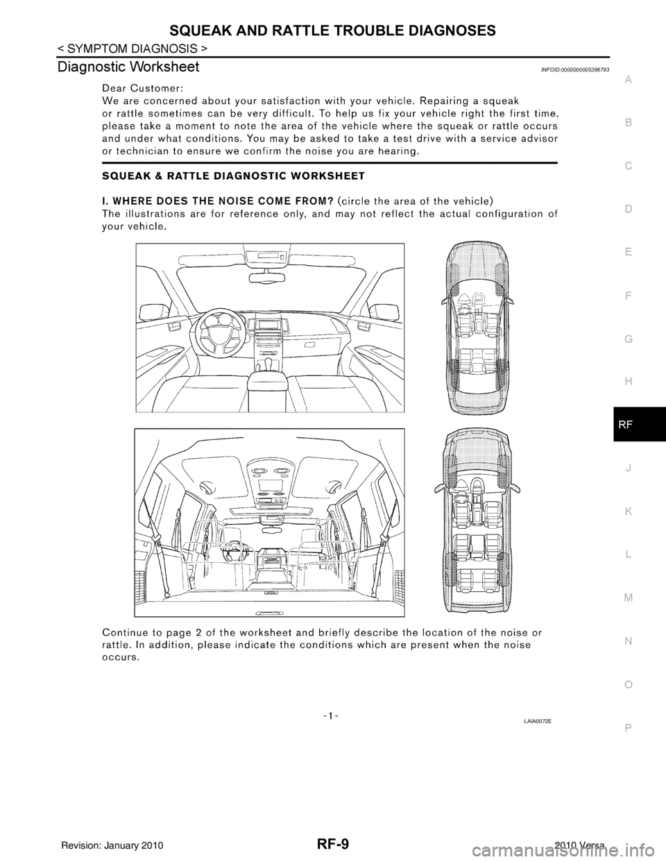
Diagnostic WorksheetINFOID:0000000005396793
LAIA0072E
Revision: January 20102010 Versa
Page 3494 of 3745
RF-10
< SYMPTOM DIAGNOSIS >
SQUEAK AND RATTLE TROUBLE DIAGNOSES
LAIA0071E
Revision: January 20102010 Versa
Page 3495 of 3745
TROUBLE DIAGNOSISRF-11
< FUNCTION DIAGNOSIS >
C
DE
F
G H
J
K L
M A
B
RF
N
O P
FUNCTION DIAGNOSIS
TROUBLE DIAGNOSIS
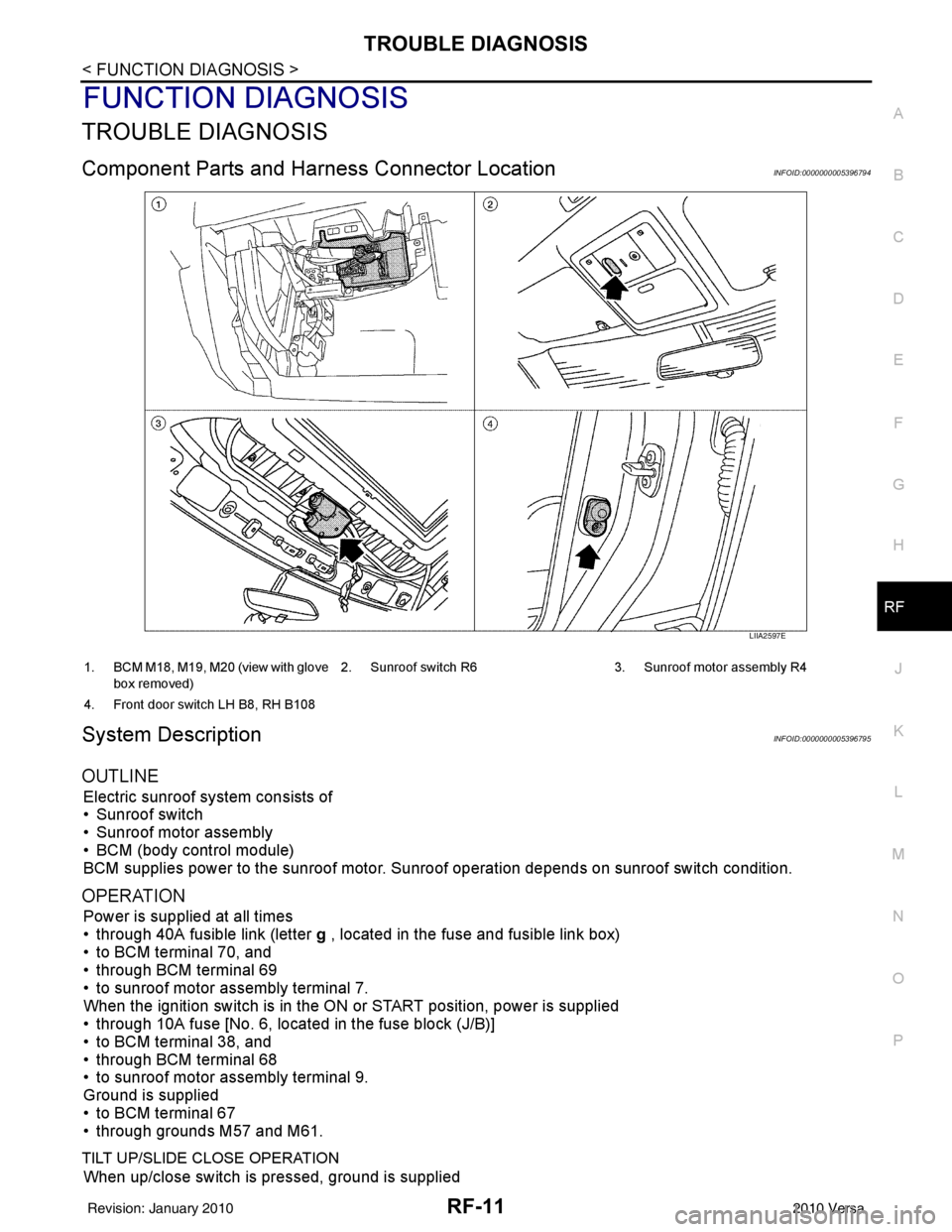
Component Parts and Har ness Connector LocationINFOID:0000000005396794
System DescriptionINFOID:0000000005396795
OUTLINE
Electric sunroof system consists of
• Sunroof switch
• Sunroof motor assembly
• BCM (body control module)
BCM supplies power to the sunroof motor. S unroof operation depends on sunroof switch condition.
OPERATION
Power is supplied at all times
• through 40A fusible link (letter g , located in the fuse and fusible link box)
• to BCM terminal 70, and
• through BCM terminal 69
• to sunroof motor assembly terminal 7.
When the ignition switch is in the ON or START position, power is supplied
• through 10A fuse [No. 6, located in the fuse block (J/B)]
• to BCM terminal 38, and
• through BCM terminal 68
• to sunroof motor assembly terminal 9.
Ground is supplied
• to BCM terminal 67
• through grounds M57 and M61.
TILT UP/SLIDE CLOSE OPERATION
When up/close switch is pressed, ground is supplied
LIIA2597E
1. BCM M18, M19, M20 (view with glove
box removed) 2. Sunroof switch R6 3. Sunroof motor assembly R4
4. Front door switch LH B8, RH B108
Revision: January 20102010 Versa
Page 3496 of 3745
RF-12
< FUNCTION DIAGNOSIS >
TROUBLE DIAGNOSIS
• to sunroof motor assembly terminal 1
• through sunroof switch terminal 3
• through sunroof switch terminal 2
• through grounds M57 and M61.
Then the sunroof will tilt up/slide closed.
TILT DOWN/SLIDE OPEN OPERATION
When down/open switch is pressed, ground is supplied
• to sunroof motor assembly terminal 5
• through sunroof switch terminal 1
• through sunroof switch terminal 2
• through grounds M57 and M61.
Then the sunroof will tilt down/slide open.
AUTO OPERATION
The power sunroof AUTO feature makes it possible to slide open and slide closed or tilt up and tilt down the
sunroof without holding the sunroof switch in the UP/CLOSE or DOWN/OPEN position.
RETAINED POWER OPERATION
When the ignition switch is turned to OFF position from ON position, power is supplied for 45 seconds
• through BCM terminal 68
• to sunroof motor assembly terminal 9.
When power is supplied, the sunroof can be operated.
The retained power operation is canceled when the front door LH or RH is opened.
RAP signal period can be changed by CONSULT-III. Refer to RF-17, "
Work Support" .
ANTI-PINCH FUNCTION
The CPU (central processing unit) of sunroof motor as sembly monitors the sunroof motor operation and the
sunroof position (fully-closed or other ) by the signals from sunroof motor.
When sunroof motor detects an interruption during the following slide close and tilt down operation, sunroof
switch controls the motor for open and the sunroof will oper ate until it reaches full up position (during tilt down
operation) or 125 mm (4.92 in) or more in an open direction (during slide close operation).
• close operation and tilt down when igniti on switch is in the ON position.
• close operation and tilt down during retained power operation.
INITIALIZATION FAILURE CONDITIONS
Initialization and teaching of system should be conducted if the following conditions exist:
• sunroof will only move in the UP/CLOSE direction, having a step by step motion
• sunroof does not have any auto operation.
INITIALIZATION PROCEDURE
If the sunroof does not open or close automatically, use the following procedure to return sunroof operation to
normal.
NOTE:
If the sunroof switch is released at any time during step 3, the procedure must be started over again. Leave
the ignition switch ON for at least 2 seconds after this procedure.
1. Push the ignition switch to the ON position.
2. Hold the sunroof switch in the tilt up position. Release the switch when the s unroof has reached the full tilt
up position.
3. Within 5 seconds of releasing the switch in step 2, hold the sunroof switch in the tilt up position again. The sunroof will move from the open position and back to t he close position. Release the switch only when
the sunroof has reached the full closed position.
RE-TEACHING CONDITIONS
Re-teaching of system should be conducted if any of the following conditions exist:
• the sunroof is manually operated using the sunroof wrench with the battery discharged or disconnected.
• the sunroof is manually operated using the sunroof wrench with the key switch in the OFF position and
retained power timed out (after approximat ely 45 seconds or with a front door open).
• the sunroof motor assembly is replaced with a new one.
• the sunroof motor is removed from the sunroof assembly and operated before it is reinstalled.
• the sunroof motor is removed from the sunroof assembly and the glass panel position is changed.
RE-TEACHING PROCEDURE
1. Using the UP/CLOSE switch, move the sunroof toward the tilt position until it stops.
Revision: January 20102010 Versa
Page 3497 of 3745
TROUBLE DIAGNOSISRF-13
< FUNCTION DIAGNOSIS >
C
DE
F
G H
J
K L
M A
B
RF
N
O P
2. Release the UP/CLOSE switch.
3. Press the UP/CLOSE switch again and continuously hold. The sunroof will begin to move in about 10 sec- onds.
4. Continue to hold the UP/CLOSE switch while the sunroof moves in a jogging motion to the full tilt position.
When the sunroof reaches the full tilt positi on, it will back up a few millimeters and stop.
5. Release the UP/CLOSE switch.
6. Within 5 seconds of releasing the UP/CLOSE s witch, press and hold the UP/CLOSE switch again. The
sunroof will move to the full open pos ition and back to the closed position.
NOTE:
If the UP/CLOSE switch is released anytime during th is teaching process, all learned profile data will be dis-
carded and the procedure will have to be started over.
7. Release the UP/CLOSE switch. Do not disconnect power for at least two seconds. The sunroof is now re-
taught.
CAN Communication System DescriptionINFOID:0000000005396796
Refer to LAN-7 .
Revision: January 20102010 Versa
Page 3498 of 3745
RF-14
< FUNCTION DIAGNOSIS >
TROUBLE DIAGNOSIS
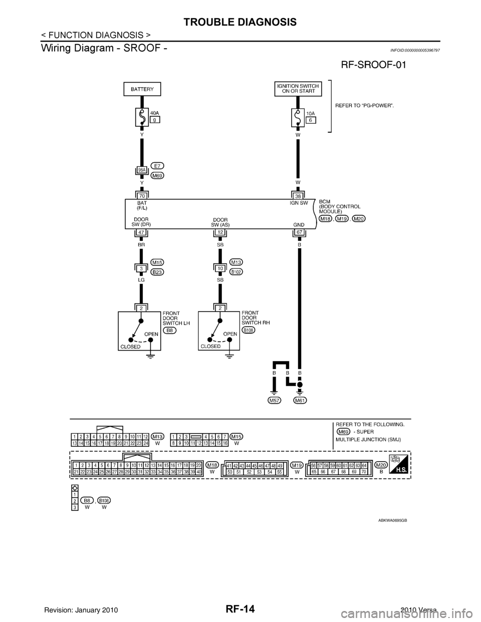
Wiring Diagram - SROOF -
INFOID:0000000005396797
ABKWA0695GB
Revision: January 20102010 Versa
Page 3499 of 3745
TROUBLE DIAGNOSISRF-15
< FUNCTION DIAGNOSIS >
C
DE
F
G H
J
K L
M A
B
RF
N
O P
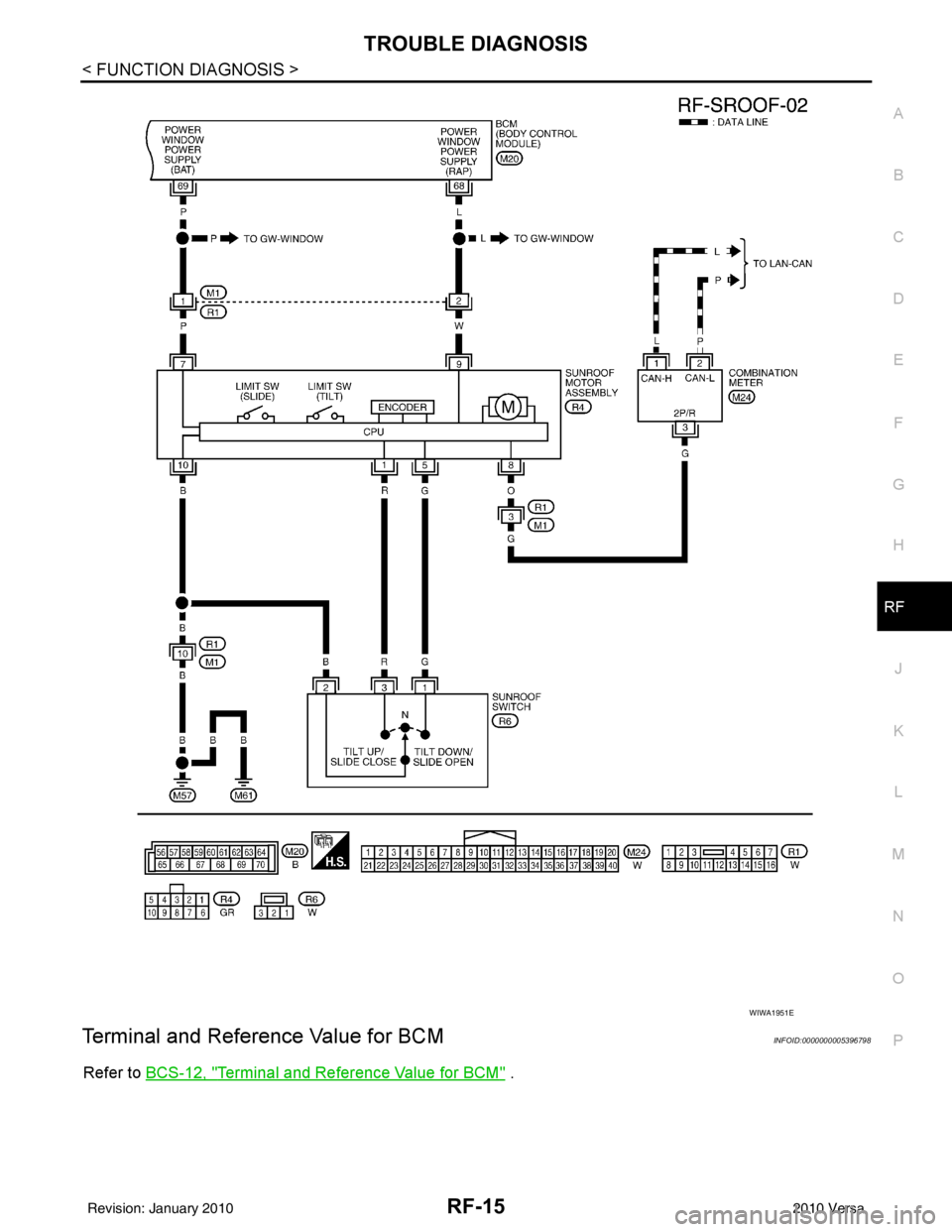
Terminal and Reference Value for BCMINFOID:0000000005396798
Refer to BCS-12, "Terminal and Reference Value for BCM" .
WIWA1951E
Revision: January 20102010 Versa
Page 3500 of 3745
RF-16
< FUNCTION DIAGNOSIS >
TROUBLE DIAGNOSIS
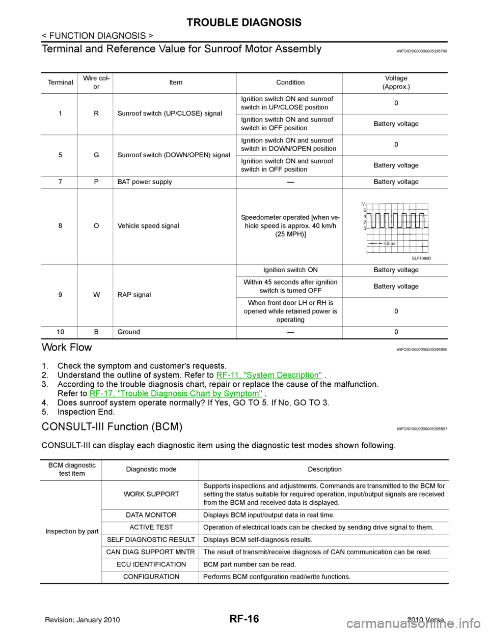
Terminal and Reference Valu e for Sunroof Motor Assembly
INFOID:0000000005396799
Work FlowINFOID:0000000005396800
1. Check the symptom and customer's requests.
2. Understand the outline of system. Refer to RF-11, "
System Description" .
3. According to the trouble diagnosis chart, repa ir or replace the cause of the malfunction.
Refer to RF-17, "
Trouble Diagnosis Chart by Symptom" .
4. Does sunroof system operate normally? If Yes, GO TO 5. If No, GO TO 3.
5. Inspection End.
CONSULT-III Function (BCM)INFOID:0000000005396801
CONSULT-III can display each diagnostic item us ing the diagnostic test modes shown following.
Te r m i n a lWire col-
or Item
Condition Vol tag e
(Approx.)
1 R Sunroof switch (UP/CLOSE) signal Ignition switch ON and sunroof
switch in UP/CLOSE position
0
Ignition switch ON and sunroof
switch in OFF position Battery voltage
5 G Sunroof switch (DOWN/OPEN) signal Ignition switch ON and sunroof
switch in DOWN/OPEN position
0
Ignition switch ON and sunroof
switch in OFF position Battery voltage
7 P BAT power supply —Battery voltage
8 O Vehicle speed signal Speedometer operated [when ve-
hicle speed is approx. 40 km/h (25 MPH)]
9 W RAP signal Ignition switch ON
Battery voltage
Within 45 seconds after ignition switch is turned OFF Battery voltage
When front door LH or RH is
opened while retained power is
operating 0
10 B Ground —0
ELF1080D
BCM diagnostic
test item Diagnostic mode
Description
Inspection by part WORK SUPPORT
Supports inspections and adjustments. Commands are transmitted to the BCM for
setting the status suitable for required operation, input/output signals are received
from the BCM and received data is displayed.
DATA MONITOR Displays BCM input/output data in real time. ACTIVE TEST Operation of electrical loads can be checked by sending drive signal to them.
SELF DIAGNOSTIC RESULT Displa ys BCM self-diagnosis results.
CAN DIAG SUPPORT MNTR The result of transmit/receive diagnosis of CAN communication can be read. ECU IDENTIFICATION BCM part number can be read.CONFIGURATION Performs BCM configuration read/write functions.
Revision: January 20102010 Versa