NISSAN TIIDA 2010 Service Repair Manual
TIIDA 2010
NISSAN
NISSAN
https://www.carmanualsonline.info/img/5/57397/w960_57397-0.png
NISSAN TIIDA 2010 Service Repair Manual
Trending: airbag off, fold seats, maintenance, tire pressure, set clock, headlamp, radiator cap
Page 3551 of 3745
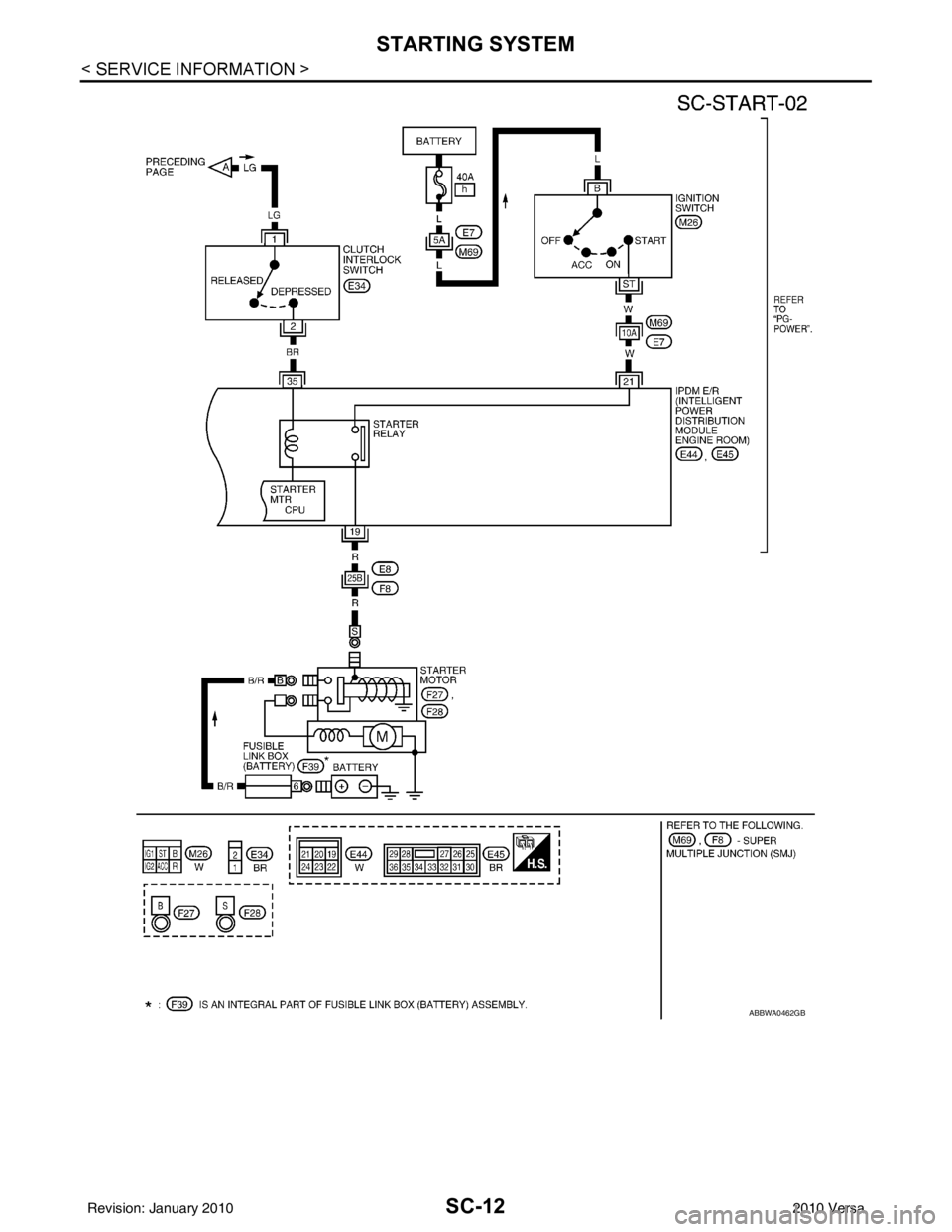
SC-12
< SERVICE INFORMATION >
STARTING SYSTEM
ABBWA0462GB
Revision: January 20102010 Versa
Page 3552 of 3745
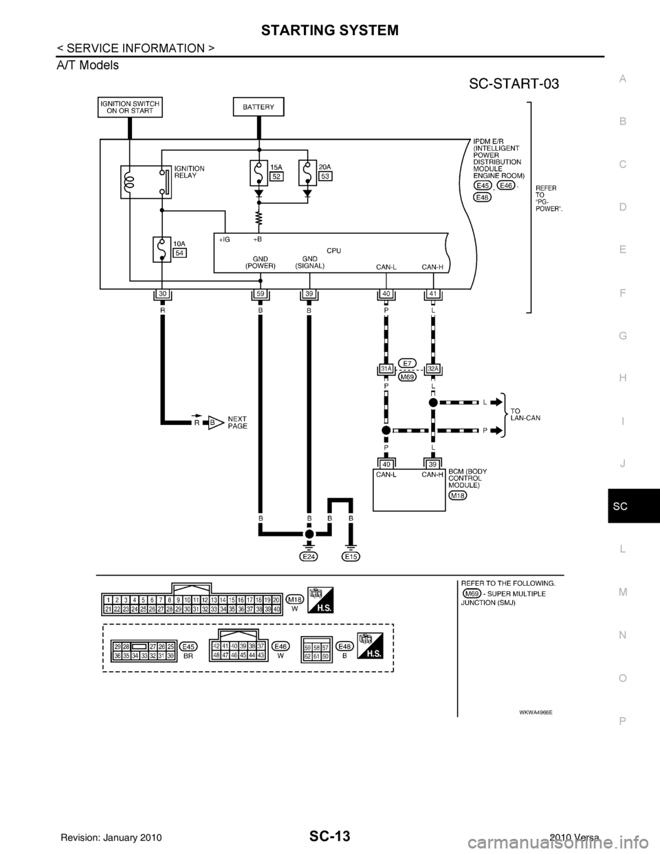
STARTING SYSTEMSC-13
< SERVICE INFORMATION >
C
DE
F
G H
I
J
L
M A
B
SC
N
O P
A/T Models
WKWA4966E
Revision: January 20102010 Versa
Page 3553 of 3745
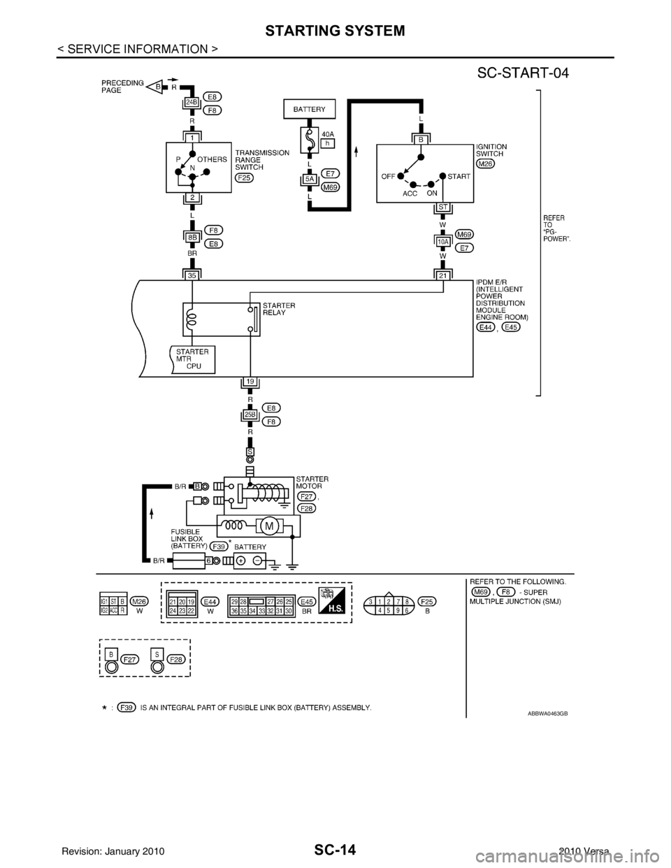
SC-14
< SERVICE INFORMATION >
STARTING SYSTEM
ABBWA0463GB
Revision: January 20102010 Versa
Page 3554 of 3745
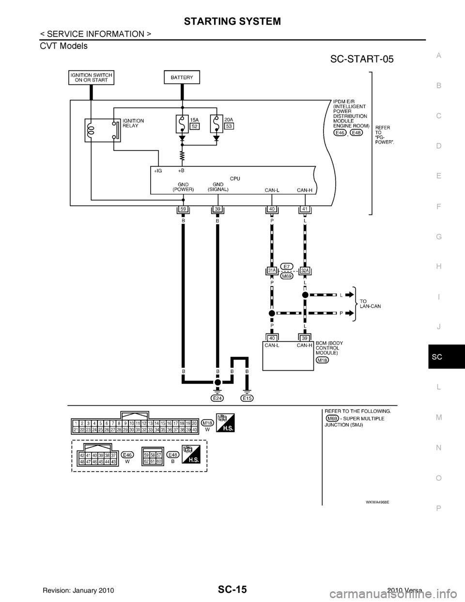
STARTING SYSTEMSC-15
< SERVICE INFORMATION >
C
DE
F
G H
I
J
L
M A
B
SC
N
O P
CVT Models
WKWA4968E
Revision: January 20102010 Versa
Page 3555 of 3745
SC-16
< SERVICE INFORMATION >
STARTING SYSTEM
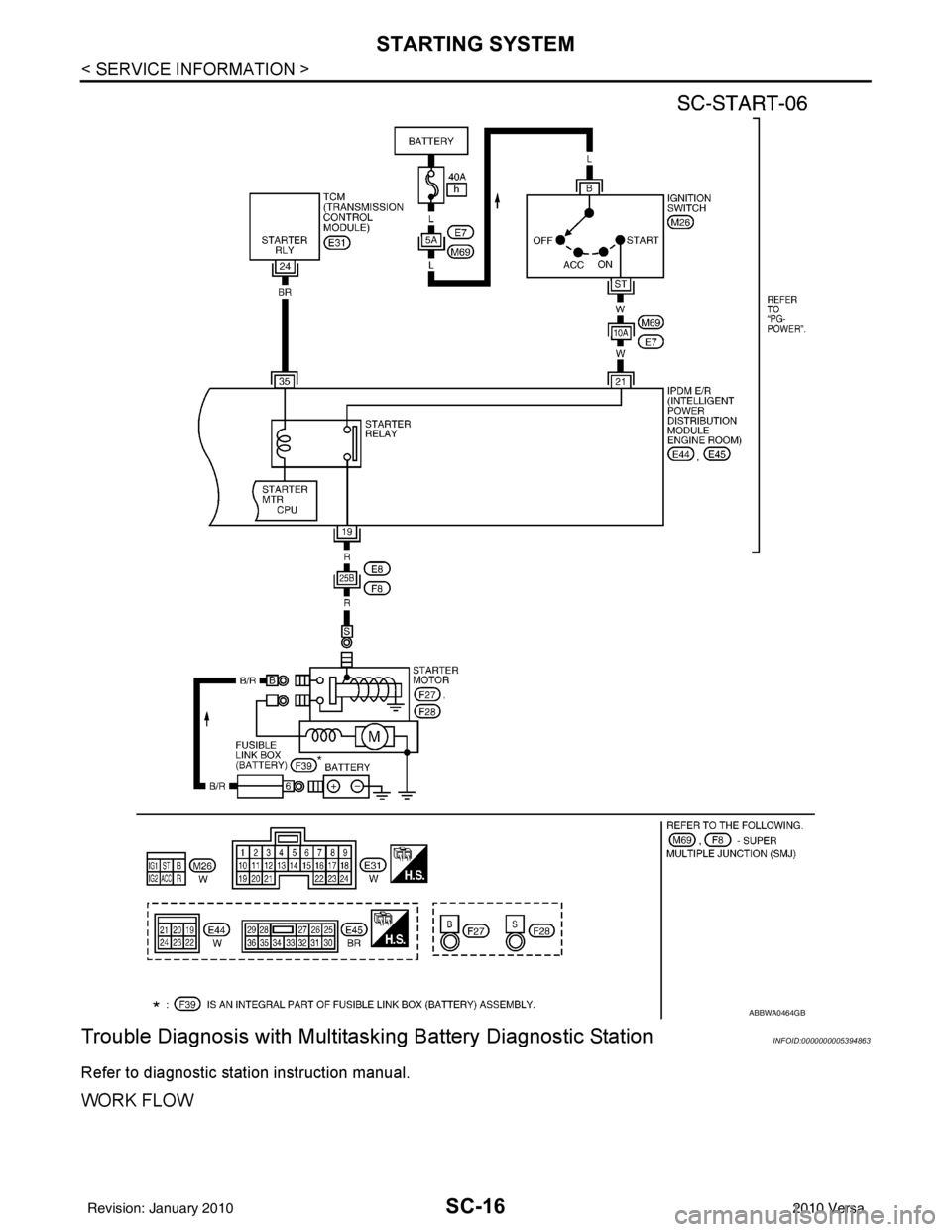
Trouble Diagnosis with Multitas king Battery Diagnostic Station
INFOID:0000000005394863
Refer to diagnostic station instruction manual.
WORK FLOW
ABBWA0464GB
Revision: January 20102010 Versa
Page 3556 of 3745
STARTING SYSTEMSC-17
< SERVICE INFORMATION >
C
DE
F
G H
I
J
L
M A
B
SC
N
O P
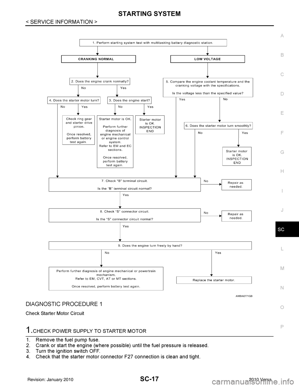
DIAGNOSTIC PROCEDURE 1
Check Starter Motor Circuit
1.CHECK POWER SUPPLY TO STARTER MOTOR
1. Remove the fuel pump fuse.
2. Crank or start the engine (where possible) until the fuel pressure is released.
3. Turn the ignition switch OFF.
4. Check that the starter motor connector F27 connection is clean and tight.
AWBIA0771GB
Revision: January 20102010 Versa
Page 3557 of 3745
SC-18
< SERVICE INFORMATION >
STARTING SYSTEM
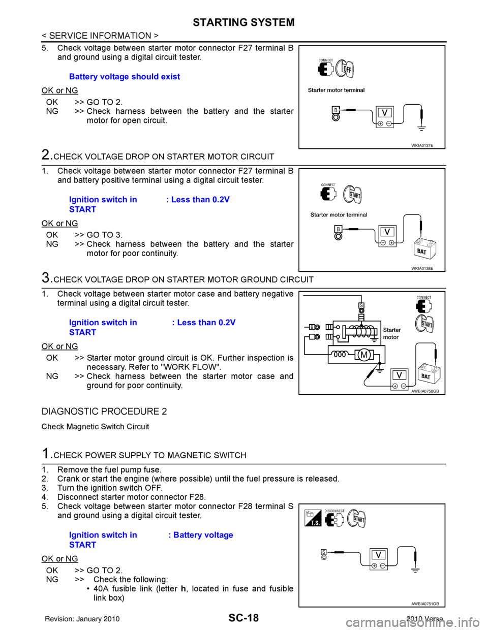
5. Check voltage between starter motor connector F27 terminal Band ground using a digital circuit tester.
OK or NG
OK >> GO TO 2.
NG >> Check harness between the battery and the starter motor for open circuit.
2.CHECK VOLTAGE DROP ON STARTER MOTOR CIRCUIT
1. Check voltage between starter motor connector F27 terminal B and battery positive terminal using a digital circuit tester.
OK or NG
OK >> GO TO 3.
NG >> Check harness between the battery and the starter motor for poor continuity.
3.CHECK VOLTAGE DROP ON STARTER MOTOR GROUND CIRCUIT
1. Check voltage between starter motor case and battery negative terminal using a digital circuit tester.
OK or NG
OK >> Starter motor ground circuit is OK. Further inspection is necessary. Refer to "WORK FLOW".
NG >> Check harness between the starter motor case and
ground for poor continuity.
DIAGNOSTIC PROCEDURE 2
Check Magnetic Switch Circuit
1.CHECK POWER SUPPLY TO MAGNETIC SWITCH
1. Remove the fuel pump fuse.
2. Crank or start the engine (where possible) until the fuel pressure is released.
3. Turn the ignition switch OFF.
4. Disconnect starter motor connector F28.
5. Check voltage between starter motor connector F28 terminal S and ground using a digital circuit tester.
OK or NG
OK >> GO TO 2.
NG >> Check the following: • 40A fusible link (letter h, located in fuse and fusible
link box)
Battery voltage should exist
WKIA0137E
Ignition switch in
START
: Less than 0.2V
WKIA0138E
Ignition switch in
START : Less than 0.2V
AWBIA0750GB
Ignition switch in
START: Battery voltage
AWBIA0751GB
Revision: January 20102010 Versa
Page 3558 of 3745
STARTING SYSTEMSC-19
< SERVICE INFORMATION >
C
DE
F
G H
I
J
L
M A
B
SC
N
O P
• 10A fuse (No. 49, M/T model s, located in the IPDM E/R)
• 15A fuse (No. 52, located in the IPDM E/R)
• 20A fuse (No. 53, located in the IPDM E/R)
• Transmission range switch, clutch interlock switch or TCM depending on equipment
• Ignition switch
• Ignition relay IPDM E/R
• Starter relay IPDM E/R
• Starter relay request ON signal from BCM
• Harness for open or short circuit
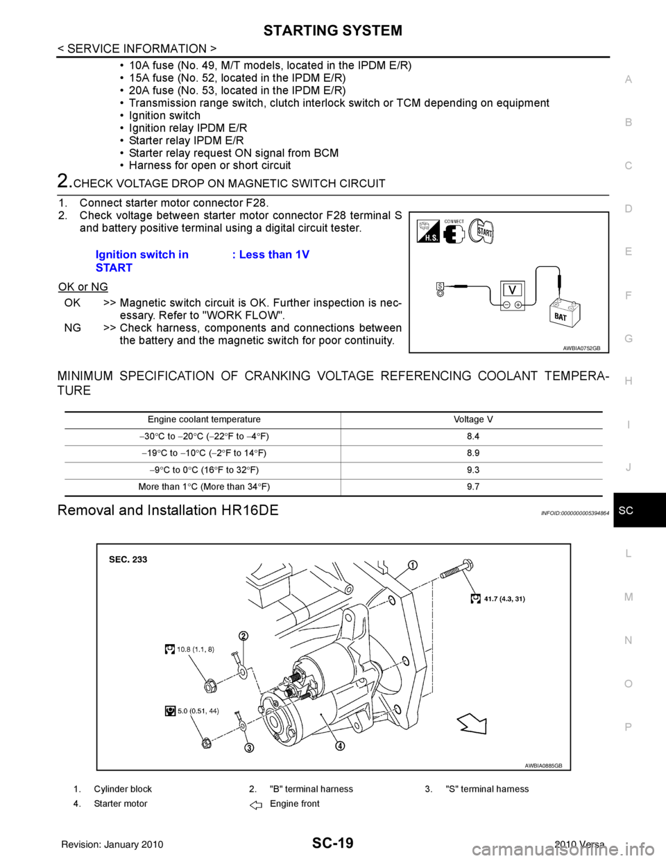
2.CHECK VOLTAGE DROP ON MAGNETIC SWITCH CIRCUIT
1. Connect starter motor connector F28.
2. Check voltage between starter motor connector F28 terminal S and battery positive terminal using a digital circuit tester.
OK or NG
OK >> Magnetic switch circuit is OK. Further inspection is nec-
essary. Refer to "WORK FLOW".
NG >> Check harness, components and connections between the battery and the magnetic switch for poor continuity.
MINIMUM SPECIFICATION OF CRANKING VO LTAGE REFERENCING COOLANT TEMPERA-
TURE
Removal and Installation HR16DEINFOID:0000000005394864
Ignition switch in
START : Less than 1V
AWBIA0752GB
Engine coolant temperature
Voltage V
− 30 °C to − 20°C ( −22 °F to −4 °F) 8.4
− 19 °C to − 10°C ( −2°F to 14 °F) 8.9
− 9 °C to 0 °C (16 °F to 32 °F) 9.3
More than 1 °C (More than 34 °F) 9.7
1. Cylinder block2. "B" terminal harness3. "S" terminal harness
4. Starter motor Engine front
AWBIA0885GB
Revision: January 20102010 Versa
Page 3559 of 3745
SC-20
< SERVICE INFORMATION >
STARTING SYSTEM
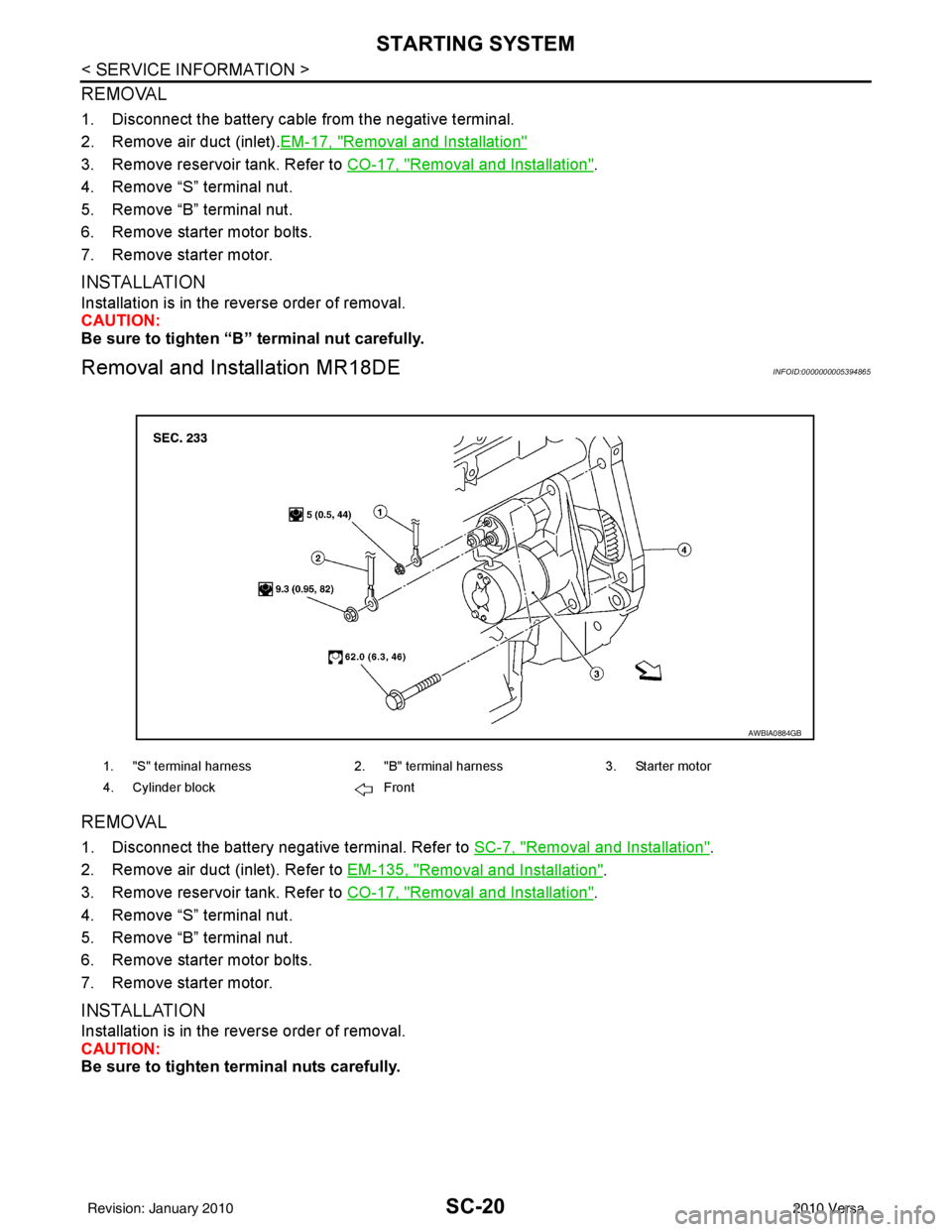
REMOVAL
1. Disconnect the battery cable from the negative terminal.
2. Remove air duct (inlet).EM-17, "
Removal and Installation"
3. Remove reservoir tank. Refer to CO-17, "Removal and Installation".
4. Remove “S” terminal nut.
5. Remove “B” terminal nut.
6. Remove starter motor bolts.
7. Remove starter motor.
INSTALLATION
Installation is in the reverse order of removal.
CAUTION:
Be sure to tighten “B” terminal nut carefully.
Removal and Installation MR18DEINFOID:0000000005394865
REMOVAL
1. Disconnect the battery negative terminal. Refer to SC-7, "Removal and Installation".
2. Remove air duct (inlet). Refer to EM-135, "
Removal and Installation".
3. Remove reservoir tank. Refer to CO-17, "
Removal and Installation".
4. Remove “S” terminal nut.
5. Remove “B” terminal nut.
6. Remove starter motor bolts.
7. Remove starter motor.
INSTALLATION
Installation is in the reverse order of removal.
CAUTION:
Be sure to tighten terminal nuts carefully.
1. "S" terminal harness 2. "B" terminal harness 3. Starter motor
4. Cylinder block Front
AWBIA0884GB
Revision: January 20102010 Versa
Page 3560 of 3745

CHARGING SYSTEMSC-21
< SERVICE INFORMATION >
C
DE
F
G H
I
J
L
M A
B
SC
N
O P
CHARGING SYSTEM
System DescriptionINFOID:0000000005394866
The generator provides DC voltage to operate the vehicl e's electrical system and to keep the battery charged.
The voltage output is controlled by the IC regulator.
Power is supplied at all times to generator terminal 3 through
• 10A fuse (No. 29, located in the fuse and fusible link box).
Power is supplied through terminal 1 to charge the batte ry and operate the vehicle's electrical system. Output
voltage is monitored at terminal 3 by the IC regulator. The charging circuit is protected by the 120A fusible link
[letter a , located in the fusible link box (battery)].
Ground is supplied
• to generator terminal 5
• through body ground F5, and
• through the generator case to the cylinder block
With the ignition switch in the ON or START position, power is supplied
• through 10A fuse [No. 3, located in the fuse block (J/B)]
• to combination meter terminal 28 for the charge warning lamp.
The IC regulator controls ground to terminal 38 of the combination meter through terminal 2 of the generator.
When the ignition is turned on and power becomes availabl e at terminal 2, this "wakes up" the regulator. The
regulator monitors charge output and grounds terminal 2 or leaves it open depending on charge output. With
power and ground supplied, the charge warning lamp will il luminate. When the generator is providing sufficient
voltage, the ground is opened and the charge warning lamp will go off.
If the charge warning lamp illuminates with the engine running, a malfunction is indicated.
Revision: January 20102010 Versa
Trending: four wheel drive, stop start, ad blue, fuel pressure, Headlamp assemblies, washer fluid, tire pressure reset
