NISSAN TIIDA 2010 Service Repair Manual
Manufacturer: NISSAN, Model Year: 2010, Model line: TIIDA, Model: NISSAN TIIDA 2010Pages: 3745, PDF Size: 73.67 MB
Page 701 of 3745
BL-192
< SERVICE INFORMATION >
BACK DOOR LOCK
Removal and Installation
INFOID:0000000005396663
BACK DOOR LOCK
Removal
1. Remove the back door finisher lower. Refer to EI-38.
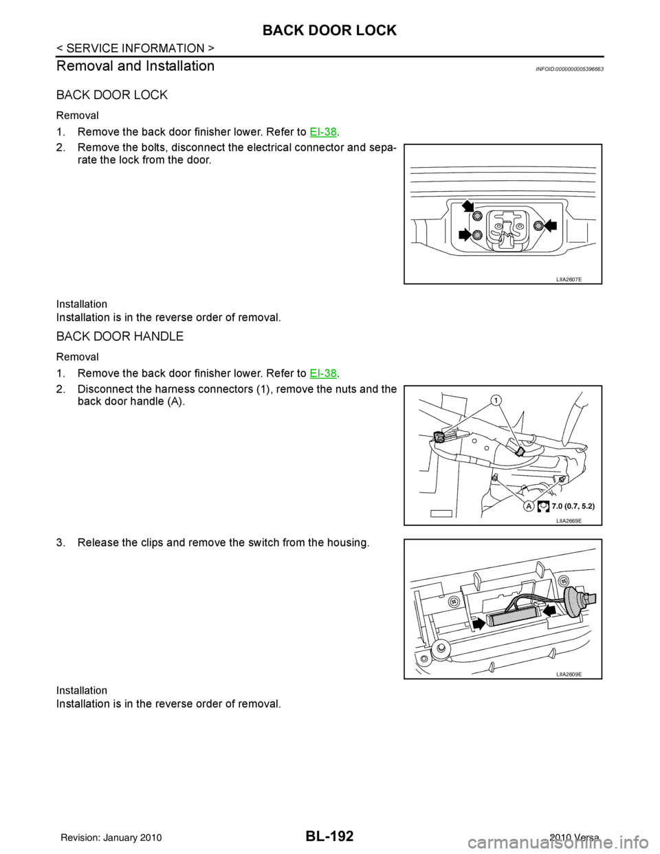
2. Remove the bolts, disconnect the electrical connector and sepa- rate the lock from the door.
Installation
Installation is in the reverse order of removal.
BACK DOOR HANDLE
Removal
1. Remove the back door finisher lower. Refer to EI-38.
2. Disconnect the harness connectors (1), remove the nuts and the back door handle (A).
3. Release the clips and remove the switch from the housing.
Installation
Installation is in the reverse order of removal.
LIIA2607E
LIIA2669E
LIIA2609E
Revision: January 20102010 Versa
Page 702 of 3745
TRUNK LIDBL-193
< SERVICE INFORMATION >
C
DE
F
G H
J
K L
M A
B
BL
N
O P
TRUNK LID
Fitting AdjustmentINFOID:0000000005396664
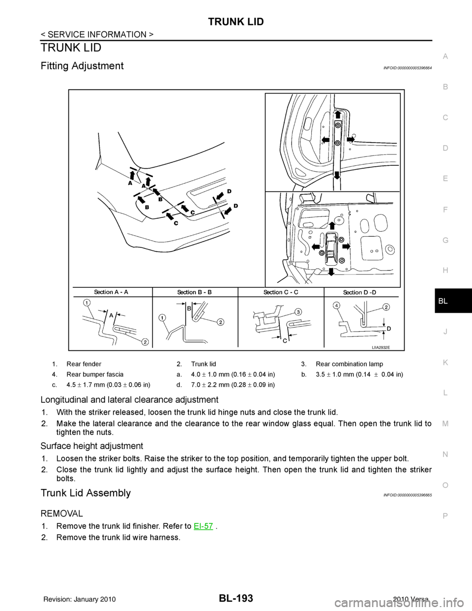
Longitudinal and latera l clearance adjustment
1. With the striker released, loosen the trunk lid hinge nuts and close the trunk lid.
2. Make the lateral clearance and the clearance to the rear window glass equal. Then open the trunk lid to
tighten the nuts.
Surface height adjustment
1. Loosen the striker bolts. Raise the striker to t he top position, and temporarily tighten the upper bolt.
2. Close the trunk lid lightly and adjust the surface height. Then open the trunk lid and tighten the striker bolts.
Trunk Lid AssemblyINFOID:0000000005396665
REMOVAL
1. Remove the trunk lid finisher. Refer to EI-57 .
2. Remove the trunk lid wire harness.
1. Rear fender 2. Trunk lid3. Rear combination lamp
4. Rear bumper fascia a. 4.0 ± 1.0 mm (0.16 ± 0.04 in) b. 3.5 ± 1.0 mm (0.14 ± 0.04 in)
c. 4.5 ± 1.7 mm (0.03 ± 0.06 in) d. 7.0 ± 2.2 mm (0.28 ± 0.09 in)
LIIA2932E
Revision: January 20102010 Versa
Page 703 of 3745
BL-194
< SERVICE INFORMATION >
TRUNK LID
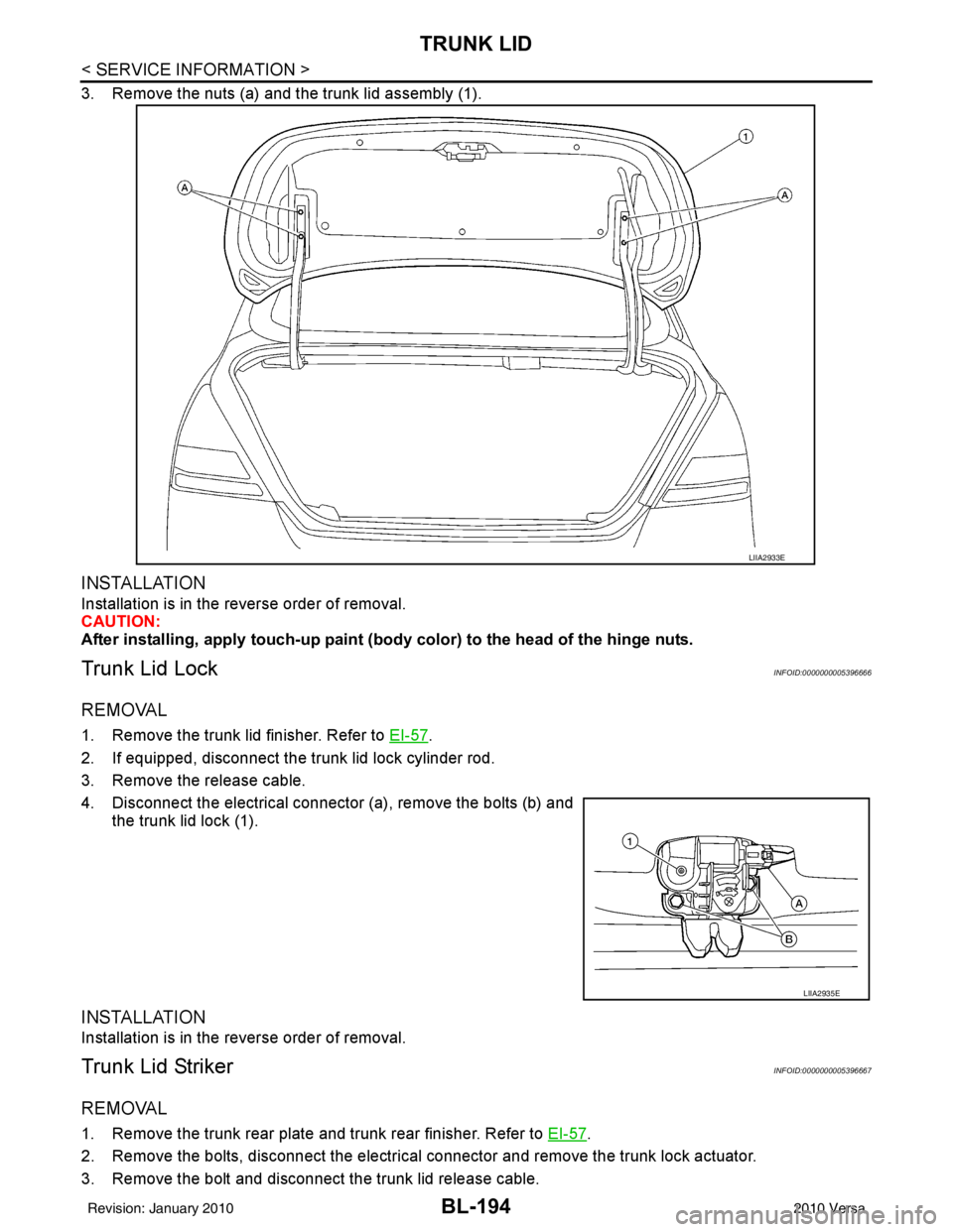
3. Remove the nuts (a) and the trunk lid assembly (1).
INSTALLATION
Installation is in the reverse order of removal.
CAUTION:
After installing, apply touch-up paint (body color) to the head of the hinge nuts.
Trunk Lid LockINFOID:0000000005396666
REMOVAL
1. Remove the trunk lid finisher. Refer to EI-57.
2. If equipped, disconnect the trunk lid lock cylinder rod.
3. Remove the release cable.
4. Disconnect the electrical connector (a), remove the bolts (b) and the trunk lid lock (1).
INSTALLATION
Installation is in the reverse order of removal.
Trunk Lid StrikerINFOID:0000000005396667
REMOVAL
1. Remove the trunk rear plate and trunk rear finisher. Refer to EI-57.
2. Remove the bolts, disconnect the electrical connector and remove the trunk lock actuator.
3. Remove the bolt and disconnect the trunk lid release cable.
LIIA2933E
LIIA2935E
Revision: January 20102010 Versa
Page 704 of 3745
TRUNK LIDBL-195
< SERVICE INFORMATION >
C
DE
F
G H
J
K L
M A
B
BL
N
O P
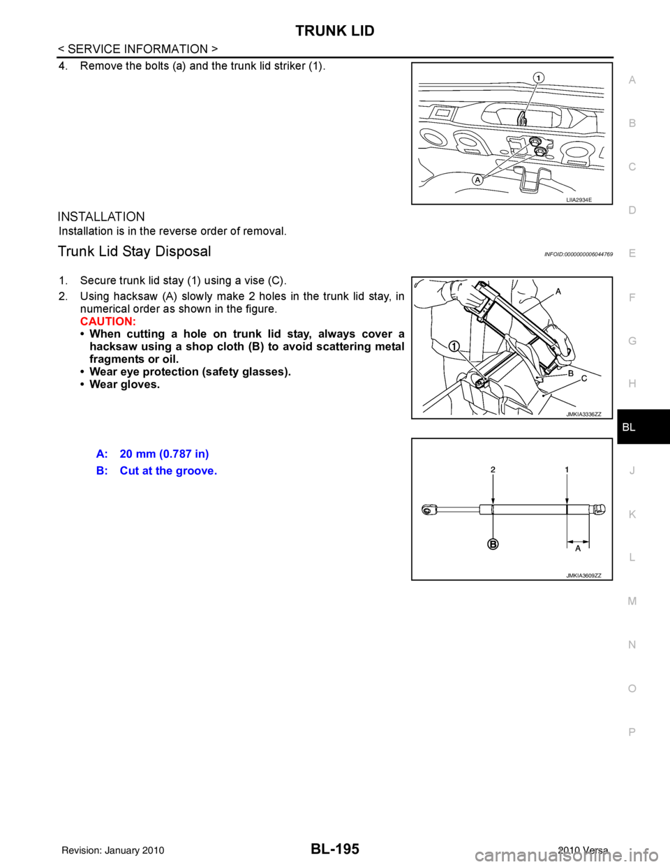
4. Remove the bolts (a) and the trunk lid striker (1).
INSTALLATION
Installation is in the reverse order of removal.
Trunk Lid Stay DisposalINFOID:0000000006044769
1. Secure trunk lid stay (1) using a vise (C).
2. Using hacksaw (A) slowly make 2 holes in the trunk lid stay, in numerical order as shown in the figure.
CAUTION:
• When cutting a hole on trunk lid stay, always cover ahacksaw using a shop cloth (B) to avoid scattering metal
fragments or oil.
• Wear eye protection (safety glasses).
• Wear gloves.
LIIA2934E
JMKIA3336ZZ
A: 20 mm (0.787 in)
B: Cut at the groove.
JMKIA3609ZZ
Revision: January 20102010 Versa
Page 705 of 3745
BL-196
< SERVICE INFORMATION >
TRUNK LID OPENER
TRUNK LID OPENER
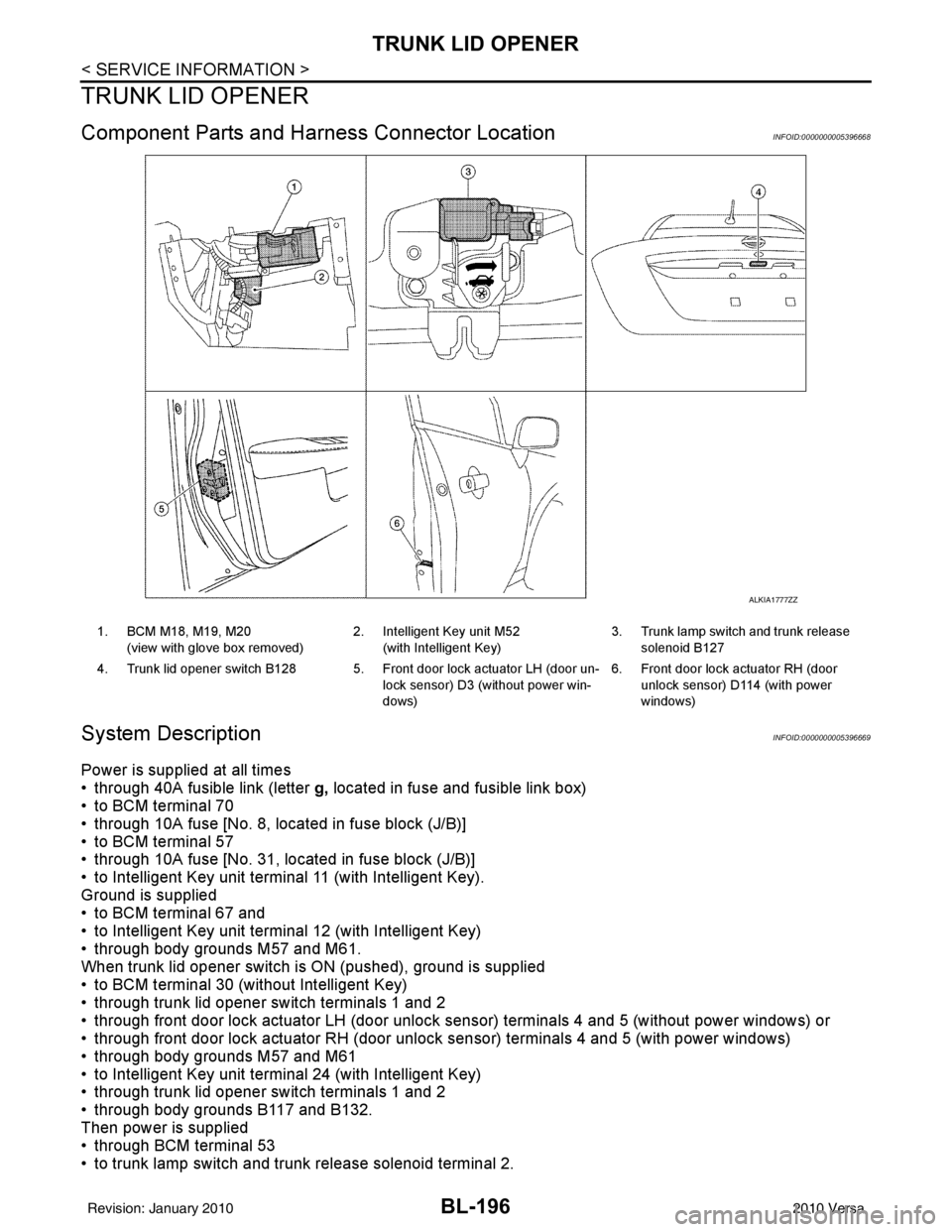
Component Parts and Harness Connector LocationINFOID:0000000005396668
System DescriptionINFOID:0000000005396669
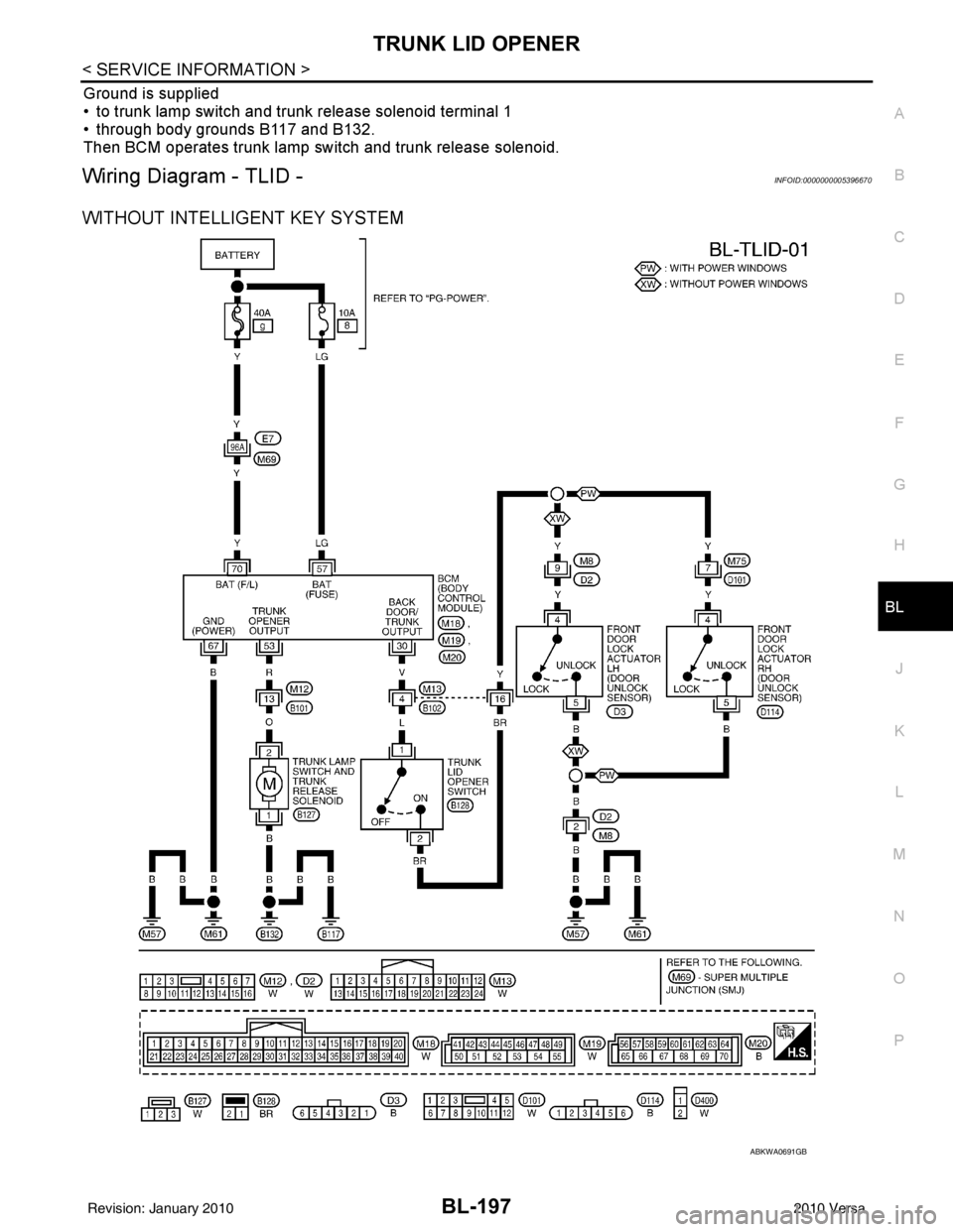
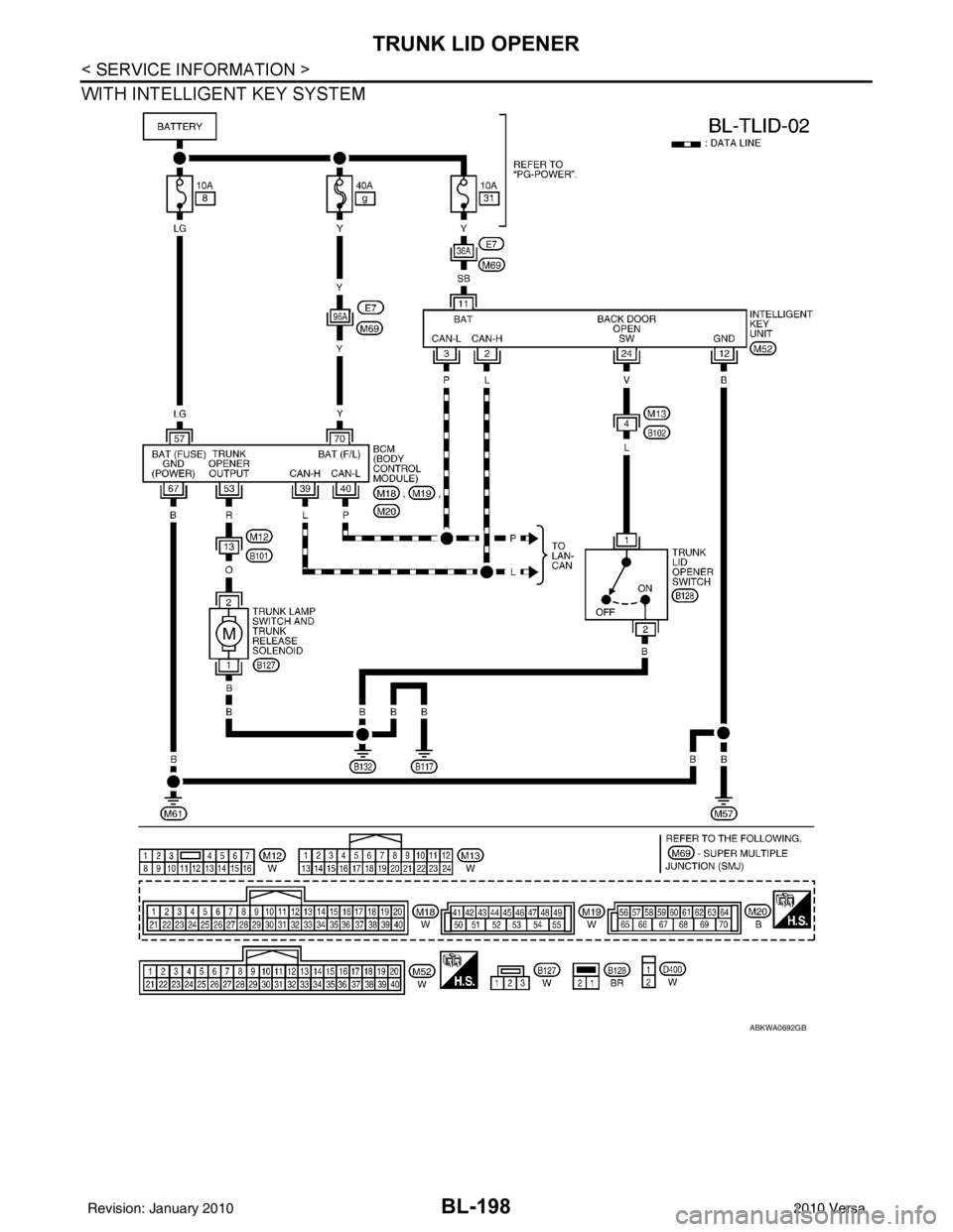
Power is supplied at all times
• through 40A fusible link (letter g, located in fuse and fusible link box)
• to BCM terminal 70
• through 10A fuse [No. 8, located in fuse block (J/B)]
• to BCM terminal 57
• through 10A fuse [No. 31, located in fuse block (J/B)]
• to Intelligent Key unit terminal 11 (with Intelligent Key).
Ground is supplied
• to BCM terminal 67 and
• to Intelligent Key unit terminal 12 (with Intelligent Key)
• through body grounds M57 and M61.
When trunk lid opener switch is ON (pushed), ground is supplied
• to BCM terminal 30 (without Intelligent Key)
• through trunk lid opener switch terminals 1 and 2
• through front door lock actuator LH (door unlock s ensor) terminals 4 and 5 (without power windows) or
• through front door lock actuator RH (door unlock sensor) terminals 4 and 5 (with power windows)
• through body grounds M57 and M61
• to Intelligent Key unit terminal 24 (with Intelligent Key)
• through trunk lid opener switch terminals 1 and 2
• through body grounds B117 and B132.
Then power is supplied
• through BCM terminal 53
• to trunk lamp switch and trunk release solenoid terminal 2.
ALKIA1777ZZ
1. BCM M18, M19, M20
(view with glove box removed) 2. Intelligent Key unit M52
(with Intelligent Key) 3. Trunk lamp switch and trunk release
solenoid B127
4. Trunk lid opener switch B128 5. Front door lock actuator LH (door un- lock sensor) D3 (without power win-
dows)6. Front door lock actuator RH (door
unlock sensor) D1 14 (with power
windows)
Revision: January 20102010 Versa
Page 706 of 3745
TRUNK LID OPENERBL-197
< SERVICE INFORMATION >
C
DE
F
G H
J
K L
M A
B
BL
N
O P
Ground is supplied
• to trunk lamp switch and trunk release solenoid terminal 1
• through body grounds B117 and B132.
Then BCM operates trunk lamp switch and trunk release solenoid.
Wiring Diagram - TLID -INFOID:0000000005396670
WITHOUT INTELLIGENT KEY SYSTEM
ABKWA0691GB
Revision: January 20102010 Versa
Page 707 of 3745
BL-198
< SERVICE INFORMATION >
TRUNK LID OPENER
WITH INTELLIGENT KEY SYSTEM
ABKWA0692GB
Revision: January 20102010 Versa
Page 708 of 3745
TRUNK LID OPENERBL-199
< SERVICE INFORMATION >
C
DE
F
G H
J
K L
M A
B
BL
N
O P
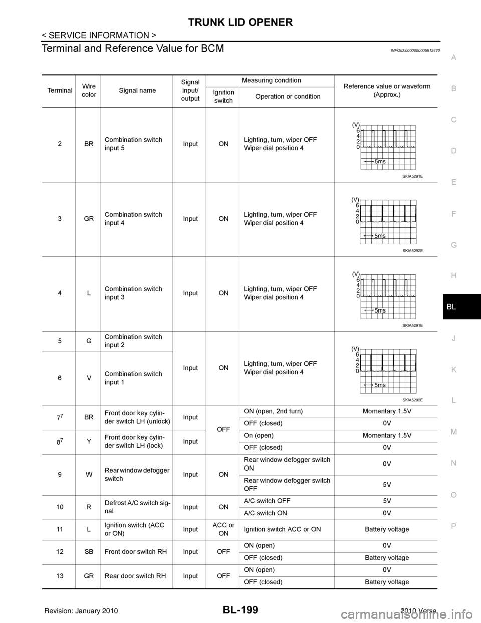
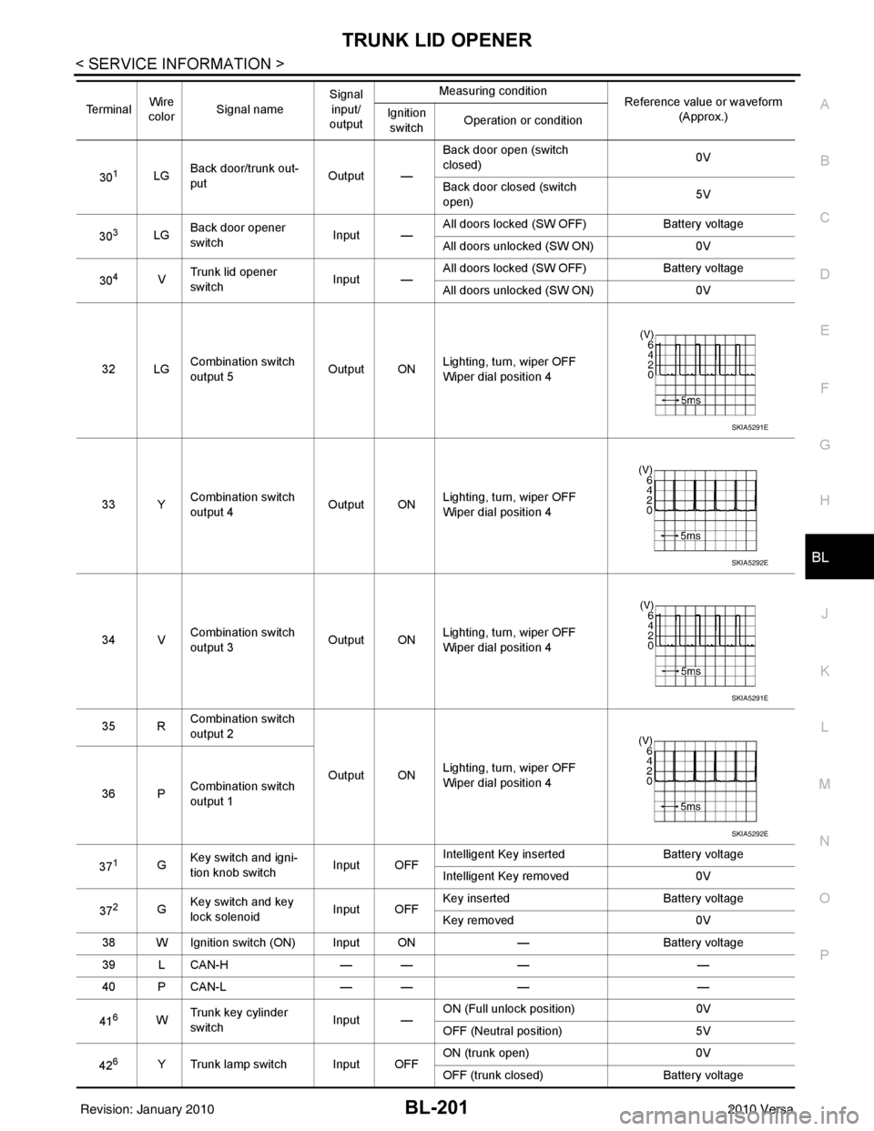
Terminal and Reference Value for BCMINFOID:0000000005612420
Te r m i n a l Wire
color Signal name Signal
input/
output Measuring condition
Reference value or waveform
(Approx.)
Ignition
switch Operation or condition
2BR Combination switch
input 5
Input ONLighting, turn, wiper OFF
Wiper dial position 4
3GR Combination switch
input 4 Input ONLighting, turn, wiper OFF
Wiper dial position 4
4L Combination switch
input 3
Input ONLighting, turn, wiper OFF
Wiper dial position 4
5G Combination switch
input 2
Input ONLighting, turn, wiper OFF
Wiper dial position 4
6V Combination switch
input 1
7
7BR Front door key cylin-
der switch LH (unlock) Input
OFFON (open, 2nd turn)
Momentary 1.5V
OFF (closed) 0V
8
7Y Front door key cylin-
der switch LH (lock) InputOn (open)
Momentary 1.5V
OFF (closed) 0V
9W Rear window defogger
switch Input ONRear window defogger switch
ON
0V
Rear window defogger switch
OFF 5V
10 R Defrost A/C switch sig-
nal
Input ONA/C switch OFF
5V
A/C switch ON 0V
11 L Ignition switch (ACC
or ON) InputACC or
ON Ignition switch ACC or ON
Battery voltage
12 SB Front door switch RH Input OFF ON (open)
0V
OFF (closed) Battery voltage
13 GR Rear door switch RH Input OFF ON (open)
0V
OFF (closed) Battery voltage
SKIA5291E
SKIA5292E
SKIA5291E
SKIA5292E
Revision: January 20102010 Versa
Page 709 of 3745
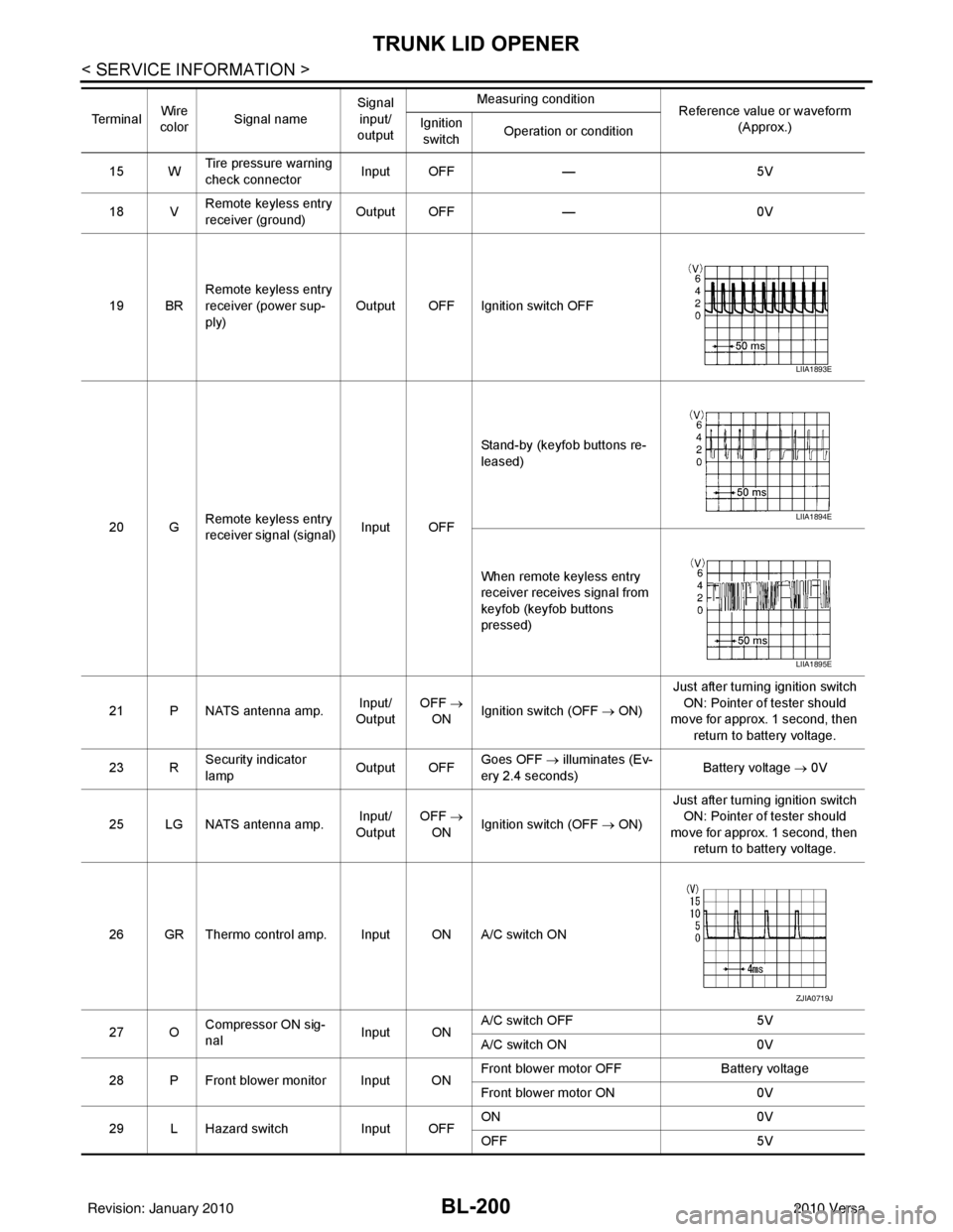
BL-200
< SERVICE INFORMATION >
TRUNK LID OPENER
15 WTire pressure warning
check connector
Input OFF
—5V
18 V Remote keyless entry
receiver (ground) Output OFF
—0V
19 BR Remote keyless entry
receiver (power sup-
ply) Output OFF Ignition switch OFF
20 G Remote keyless entry
receiver signal (signal)
Input OFFStand-by (keyfob buttons re-
leased)
When remote keyless entry
receiver receives signal from
keyfob (keyfob buttons
pressed)
21 P NATS antenna amp. Input/
Output OFF
→
ON Ignition switch (OFF
→ ON)Just after turning ignition switch
ON: Pointer of tester should
move for approx. 1 second, then
return to battery voltage.
23 R Security indicator
lamp Output OFF
Goes OFF
→ illuminates (Ev-
ery 2.4 seconds) Battery voltage
→ 0V
25 LG NATS antenna amp. Input/
Output OFF
→
ON Ignition switch (OFF
→ ON)Just after turning ignition switch
ON: Pointer of tester should
move for approx. 1 second, then return to battery voltage.
26 GR Thermo control amp. Input ON A/C switch ON
27 O Compressor ON sig-
nal Input ONA/C switch OFF
5V
A/C switch ON 0V
28 P Front blower monitor Input ON Front blower motor OFF
Battery voltage
Front blower motor ON 0V
29 L Hazard switch Input OFFON
0V
OFF 5V
Te r m i n a l
Wire
color Signal name Signal
input/
output Measuring condition
Reference value or waveform
(Approx.)
Ignition
switch Operation or condition
LIIA1893E
LIIA1894E
LIIA1895E
ZJIA0719J
Revision: January 20102010 Versa
Page 710 of 3745
TRUNK LID OPENERBL-201
< SERVICE INFORMATION >
C
DE
F
G H
J
K L
M A
B
BL
N
O P
301LG Back door/trunk out-
put Output —Back door open (switch
closed)
0V
Back door closed (switch
open) 5V
30
3LG Back door opener
switch
Input —All doors locked (SW OFF)
Battery voltage
All doors unlocked (SW ON) 0V
30
4V Trunk lid opener
switch
Input —All doors locked (SW OFF)
Battery voltage
All doors unlocked (SW ON) 0V
32 LG Combination switch
output 5 Output ONLighting, turn, wiper OFF
Wiper dial position 4
33 Y Combination switch
output 4 Output ON
Lighting, turn, wiper OFF
Wiper dial position 4
34 V Combination switch
output 3
Output ONLighting, turn, wiper OFF
Wiper dial position 4
35 R Combination switch
output 2
Output ONLighting, turn, wiper OFF
Wiper dial position 4
36 P Combination switch
output 1
37
1G Key switch and igni-
tion knob switch Input OFFIntelligent Key inserted
Battery voltage
Intelligent Key removed 0V
37
2G Key switch and key
lock solenoid Input OFFKey inserted
Battery voltage
Key removed 0V
38 W Ignition switch (ON) Input ON —Battery voltage
39 L CAN-H — —— —
40 P CAN-L — —— —
41
6W Trunk key cylinder
switch
Input —ON (Full unlock position)
0V
OFF (Neutral position) 5V
42
6Y Trunk lamp switch Input OFF ON (trunk open)
0V
OFF (trunk closed) Battery voltage
Te r m i n a l
Wire
color Signal name Signal
input/
output Measuring condition
Reference value or waveform
(Approx.)
Ignition
switch Operation or condition
SKIA5291E
SKIA5292E
SKIA5291E
SKIA5292E
Revision: January 20102010 Versa