engine control system NISSAN TIIDA 2011 Service Manual Online
[x] Cancel search | Manufacturer: NISSAN, Model Year: 2011, Model line: TIIDA, Model: NISSAN TIIDA 2011Pages: 3787, PDF Size: 78.35 MB
Page 1079 of 3787
CVT-24
< SERVICE INFORMATION >[RE0F08B]
CVT SYSTEM
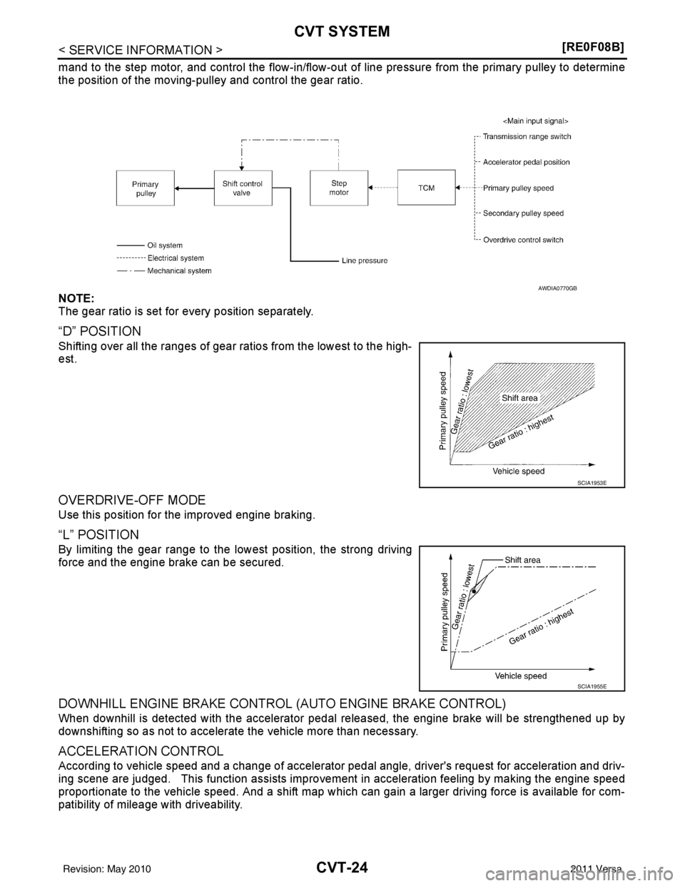
mand to the step motor, and control the flow-in/flow-out of line pressure from the primary pulley to determine
the position of the moving-pulley and control the gear ratio.
NOTE:
The gear ratio is set for every position separately.
“D” POSITION
Shifting over all the ranges of gear ratios from the lowest to the high-
est.
OVERDRIVE-OFF MODE
Use this position for the improved engine braking.
“L” POSITION
By limiting the gear range to the lowest position, the strong driving
force and the engine brake can be secured.
DOWNHILL ENGINE BRAKE CONTROL
(AUTO ENGINE BRAKE CONTROL)
When downhill is detected with the accelerator pedal released, the engine brake will be strengthened up by
downshifting so as not to accelerate the vehicle more than necessary.
ACCELERATION CONTROL
According to vehicle speed and a change of accelerator pedal angle, driver's request for acceleration and driv-
ing scene are judged. This function assists improvem ent in acceleration feeling by making the engine speed
proportionate to the vehicle speed. And a shift map which can gain a larger driving force is available for com-
patibility of mileage with driveability.
AWDIA0770GB
SCIA1953E
SCIA1955E
Revision: May 2010 2011 Versa
Page 1080 of 3787
CVT SYSTEMCVT-25
< SERVICE INFORMATION > [RE0F08B]
D
E
F
G H
I
J
K L
M A
B
CVT
N
O P
Lock-up and Select ControlINFOID:0000000005928741
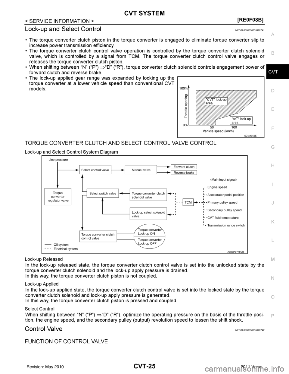
• The torque converter clutch piston in the torque conv erter is engaged to eliminate torque converter slip to
increase power transmission efficiency.
• The torque converter clutch control valve operation is controlled by the torque converter clutch solenoid
valve, which is controlled by a signal from TCM. The torque converter clutch control valve engages or
releases the torque converter clutch piston.
• When shifting between “N” (“P”) ⇒“D” (“R”), torque converter clutch solenoid controls engagement power of
forward clutch and reverse brake.
• The lock-up applied gear range was expanded by locking up the torque converter at a lower vehicle speed than conventional CVT
models.
TORQUE CONVERTER CLUTCH AND SELECT CONTROL VALVE CONTROL
Lock-up and Select Control System Diagram
Lock-up Released
In the lock-up released state, the torque converter clutch control valve is set into the unlocked state by the
torque converter clutch solenoid and the lock-up apply pressure is drained.
In this way, the torque converter clutch piston is not coupled.
Lock-up Applied
In the lock-up applied state, the torque converter clutch control valve is set into the locked state by the torque
converter clutch solenoid and lock-up apply pressure is generated.
In this way, the torque converter clutch piston is pressed and coupled.
Select Control
When shifting between “N” (“P”) ⇒“D” (“R”), optimize the operating pressure on the basis of the throttle posi-
tion, the engine speed, and the secondary pulley (out put) revolution speed to lessen the shift shock.
Control ValveINFOID:0000000005928742
FUNCTION OF CONTROL VALVE
SCIA1958E
AWDIA0778GB
Revision: May 2010 2011 Versa
Page 1086 of 3787
TROUBLE DIAGNOSISCVT-31
< SERVICE INFORMATION > [RE0F08B]
D
E
F
G H
I
J
K L
M A
B
CVT
N
O P
TCM Power Supply (Memory Back-up)
Transaxle assembly is protected by limiting the engine torque when the memory back-up power supply (for
controlling) from the battery is not supplied to TCM.
Normal statues is restored when turning the ignition switch
OFF to ON after the normal power supply.
How to Perform Trouble Diagnosis for Quick and Accurate RepairINFOID:0000000005928750
INTRODUCTION
The TCM receives a signal from the vehicle speed sensor, transmission range switch and provides shift con-
trol or lock-up control via CVT solenoid valves.
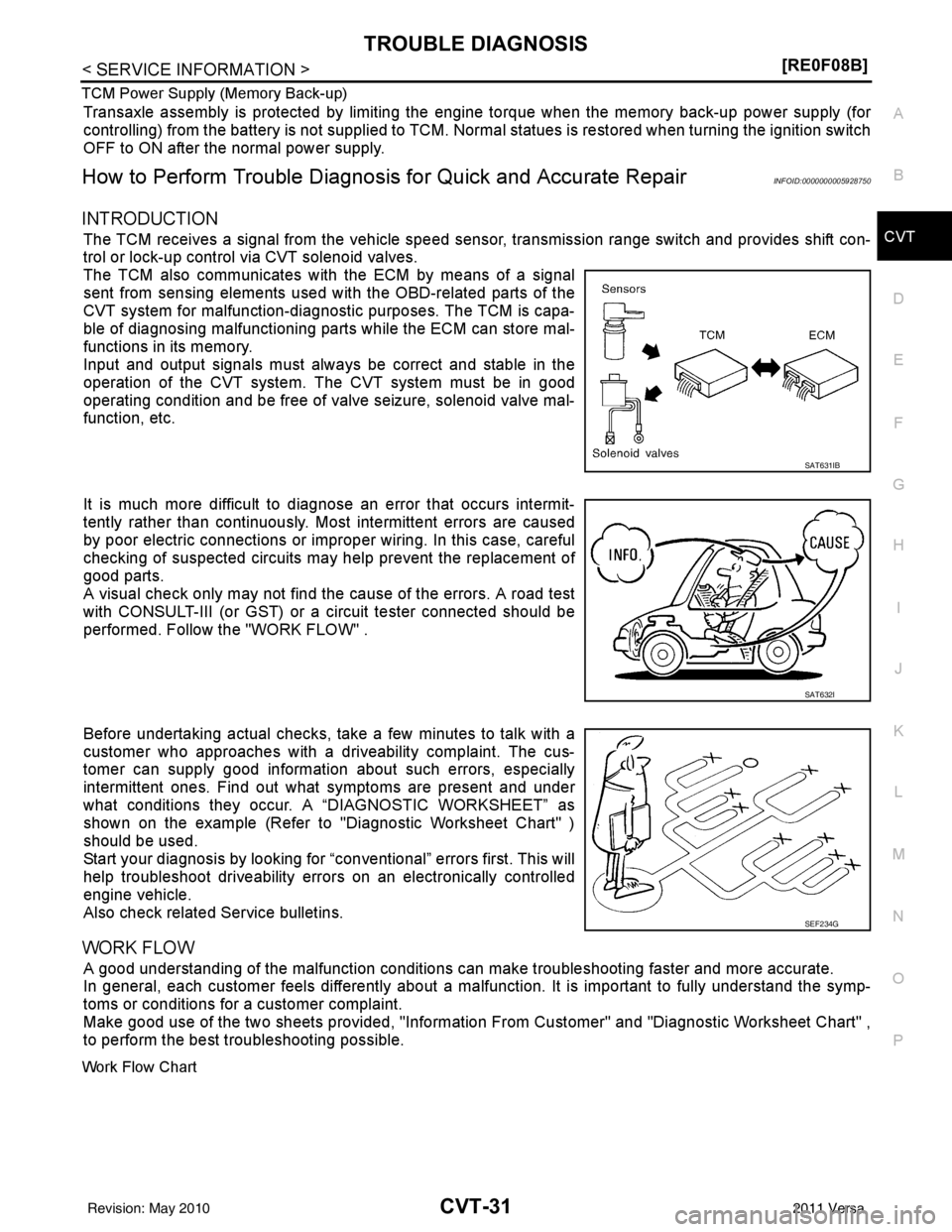
The TCM also communicates with the ECM by means of a signal
sent from sensing elements used wit h the OBD-related parts of the
CVT system for malfunction-diagnos tic purposes. The TCM is capa-
ble of diagnosing malfunctioning parts while the ECM can store mal-
functions in its memory.
Input and output signals must always be correct and stable in the
operation of the CVT system. The CVT system must be in good
operating condition and be free of valve seizure, solenoid valve mal-
function, etc.
It is much more difficult to diagnose an error that occurs intermit-
tently rather than continuously. Most intermittent errors are caused
by poor electric connections or impr oper wiring. In this case, careful
checking of suspected circuits may help prevent the replacement of
good parts.
A visual check only may not find t he cause of the errors. A road test
with CONSULT-III (or GST) or a circuit tester connected should be
performed. Follow the "WORK FLOW" .
Before undertaking actual checks, take a few minutes to talk with a
customer who approaches with a driveability complaint. The cus-
tomer can supply good information about such errors, especially
intermittent ones. Find out what symptoms are present and under
what conditions they occur. A “DIAGNOSTIC WORKSHEET” as
shown on the example (Refer to "Diagnostic Worksheet Chart" )
should be used.
Start your diagnosis by looking for “conventional” errors first. This will
help troubleshoot driveability errors on an electronically controlled
engine vehicle.
Also check related Service bulletins.
WORK FLOW
A good understanding of the malfunction conditions can make troubleshooting faster and more accurate.
In general, each customer feels differently about a malf unction. It is important to fully understand the symp-
toms or conditions for a customer complaint.
Make good use of the two sheets provided, "Information From Customer" and "Diagnostic Worksheet Chart" ,
to perform the best troubleshooting possible.
Work Flow Chart
SAT631IB
SAT632I
SEF234G
Revision: May 2010 2011 Versa
Page 1151 of 3787
CVT-96
< SERVICE INFORMATION >[RE0F08B]
P0746 PRESSURE CONTROL SOLENOID A
P0746 PRESSURE CONTROL SOLENOID A
DescriptionINFOID:0000000005928843
• The line pressure solenoid valve is included in the control valve assembly.
• The line pressure solenoid valve regulates the oil pum
p discharge pressure to suit the driving condition in
response to a signal sent from the TCM.
CONSULT-III Reference Value in Data Monitor ModeINFOID:0000000005928844
Remarks: Specification data are reference values.
On Board Diagn osis LogicINFOID:0000000005928845
• This is an OBD-II self-diagnostic item.
• Diagnostic trouble code “P0746” with CONSULT-III is detected under the following conditions.
- Unexpected gear ratio was detected in the LOW side due to excessively low line pressure.
Possible CauseINFOID:0000000005928846
• Line pressure control system
• Secondary speed sensor
• Primary speed sensor
DTC Confirmation ProcedureINFOID:0000000005928847
CAUTION:
Always drive vehicle at a safe speed.
NOTE:
If “DTC Confirmation Procedure” has been previously performed, alw ays turn ignition switch OFF and
wait at least 10 seconds before performing the next test.
After the repair, touch “ERASE” on “SELF-DIAG RESULTS” and then perform the following procedure to con-
firm the malfunction is eliminated.
WITH CONSULT-III
1. Turn ignition switch ON and select “DATA MONI TOR” mode for “TRANSMISSION” with CONSULT-III.
2. Start engine and maintain the following conditions for at least 10 consecutive seconds. Test start from 0
km/h (0 MPH).
ATF TEMP SEN: 1.0 - 2.0 V
ACC PEDAL OPEN: More than 1.0/8
RANGE: “D” position
VEHICLE SPEED: 10 km/h (6 MPH) More than
Driving location: Driving the vehicle uphill (increased engine load) will help maintain the driving
conditions required for this test.
3. If DTC is detected, go to CVT-96, "
Diagnosis Procedure".
WITH GST
Follow the procedure “WITH CONSULT-III”.
Diagnosis ProcedureINFOID:0000000005928848
1.CHECK LINE PRESSURE
Perform line pressure test. Refer to CVT-37, "
Inspections before Trouble Diagnosis".
OK or NG
OK >> GO TO 2.
NG >> Repair or replace damaged parts. Refer to CVT-37, "
Inspections before Trouble Diagnosis".
2.DETECT MALFUNCTIONING ITEM
Check line pressure solenoid valve. Refer to CVT-94, "
Component Inspection".
Item nameCondition Display value (Approx.)
PRI PRESS “N” position idle 0.4 MPa
Revision: May 2010 2011 Versa
Page 1153 of 3787
CVT-98
< SERVICE INFORMATION >[RE0F08B]
P0776 PRESSURE CONTROL SOLENOID B
P0776 PRESSURE CONTROL SOLENOID B
DescriptionINFOID:0000000005928849
• The secondary pressure solenoid valve is included in the control valve assembly.
• The secondary pressure solenoid valve regulates the secondary pressure to suit the driving condition in
response to a signal sent from the TCM.
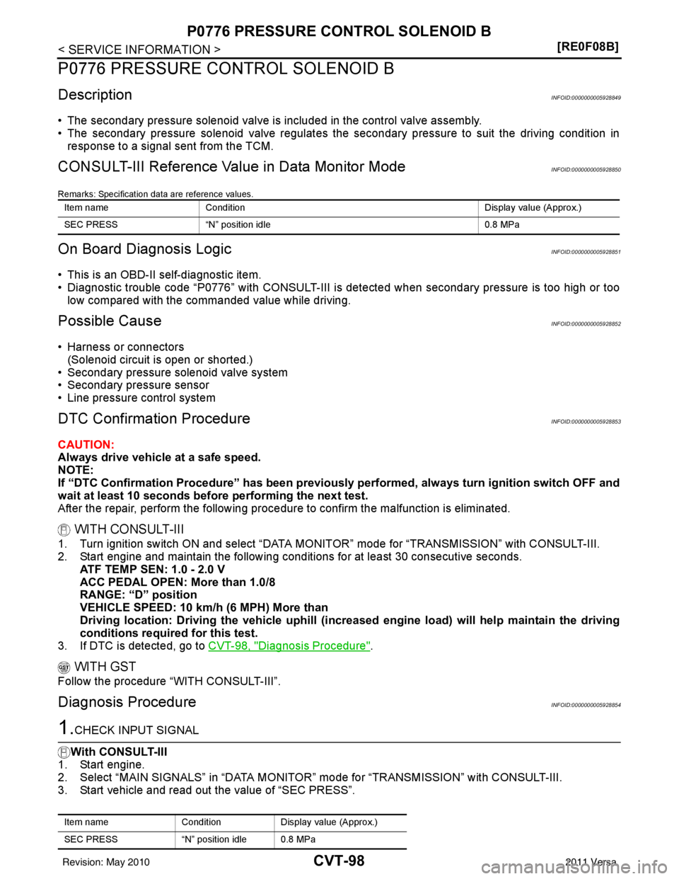
CONSULT-III Reference Value in Data Monitor ModeINFOID:0000000005928850
Remarks: Specification data are reference values.
On Board Diagn osis LogicINFOID:0000000005928851
• This is an OBD-II self-diagnostic item.
• Diagnostic trouble code “P0776” with CONSULT-III is det ected when secondary pressure is too high or too
low compared with the commanded value while driving.
Possible CauseINFOID:0000000005928852
• Harness or connectors (Solenoid circuit is open or shorted.)
• Secondary pressure solenoid valve system
• Secondary pressure sensor
• Line pressure control system
DTC Confirmation ProcedureINFOID:0000000005928853
CAUTION:
Always drive vehicle at a safe speed.
NOTE:
If “DTC Confirmation Procedure” has been previously performed, alw ays turn ignition switch OFF and
wait at least 10 seconds before performing the next test.
After the repair, perform the following proc edure to confirm the malfunction is eliminated.
WITH CONSULT-III
1. Turn ignition switch ON and select “DATA MONI TOR” mode for “TRANSMISSION” with CONSULT-III.
2. Start engine and maintain the following conditions for at least 30 consecutive seconds.
ATF TEMP SEN: 1.0 - 2.0 V
ACC PEDAL OPEN: More than 1.0/8
RANGE: “D” position
VEHICLE SPEED: 10 km/h (6 MPH) More than
Driving location: Driving the vehicle uphill (increased engine load) will help maintain the driving
conditions required for this test.
3. If DTC is detected, go to CVT-98, "
Diagnosis Procedure".
WITH GST
Follow the procedure “WITH CONSULT-III”.
Diagnosis ProcedureINFOID:0000000005928854
1.CHECK INPUT SIGNAL
With CONSULT-III
1. Start engine.
2. Select “MAIN SIGNALS” in “DATA MONITO R” mode for “TRANSMISSION” with CONSULT-III.
3. Start vehicle and read out the value of “SEC PRESS”.
Item name Condition Display value (Approx.)
SEC PRESS “N” position idle 0.8 MPa
Item nameConditionDisplay value (Approx.)
SEC PRESS “N” position idle 0.8 MPa
Revision: May 2010 2011 Versa
Page 1166 of 3787
P0868 TRANSMISSION FLUID PRESSURECVT-111
< SERVICE INFORMATION > [RE0F08B]
D
E
F
G H
I
J
K L
M A
B
CVT
N
O P
P0868 TRANSMISSION FLUID PRESSURE
DescriptionINFOID:0000000005928876
• The secondary pressure solenoid valve is included in the control valve assembly.
• The secondary pressure solenoid valve regulates the secondary pressure to suit the driving condition in
response to a signal sent from the TCM.
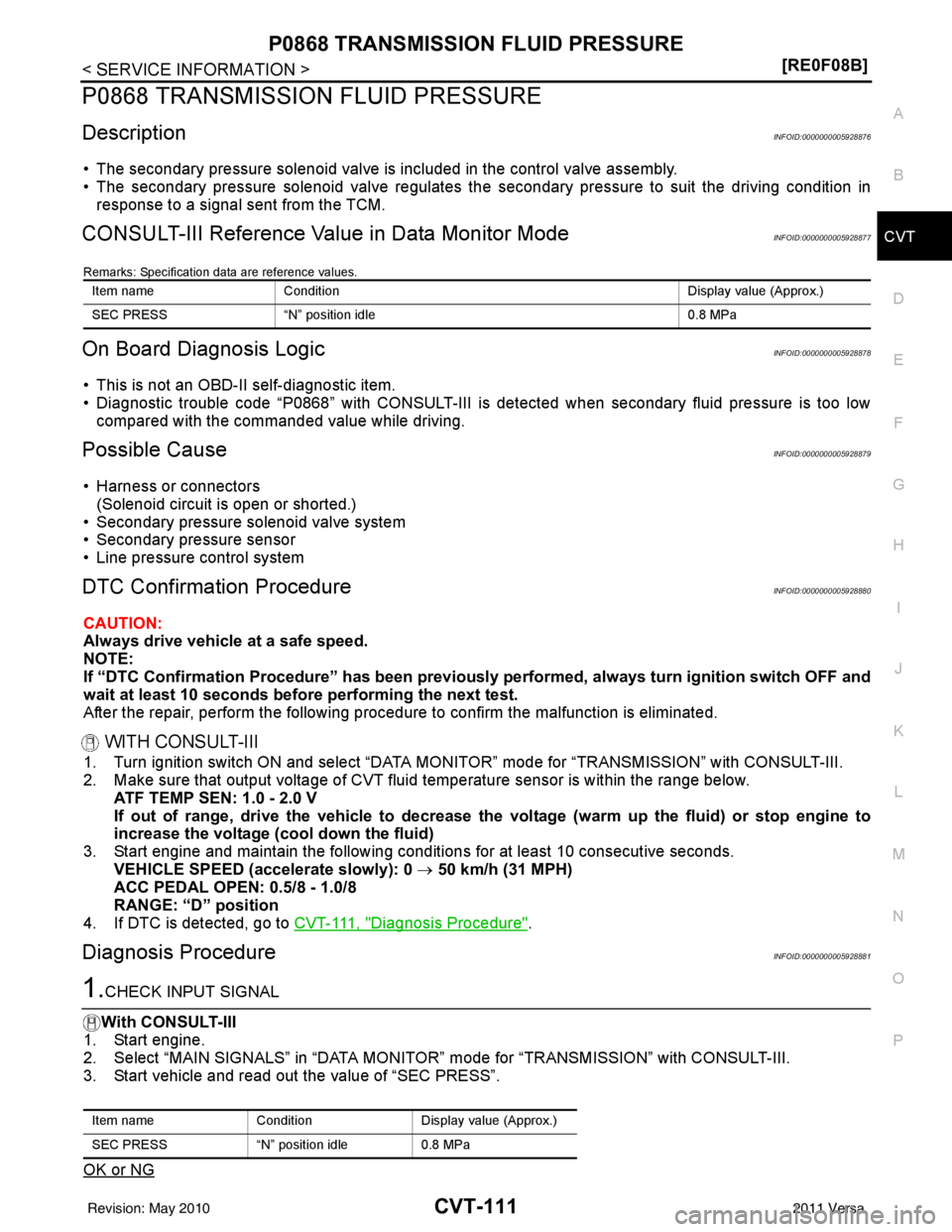
CONSULT-III Reference Val ue in Data Monitor ModeINFOID:0000000005928877
Remarks: Specification data are reference values.
On Board Diagnosis LogicINFOID:0000000005928878
• This is not an OBD-II self-diagnostic item.
• Diagnostic trouble code “P0868” with CONSULT-III is det ected when secondary fluid pressure is too low
compared with the commanded value while driving.
Possible CauseINFOID:0000000005928879
• Harness or connectors (Solenoid circuit is open or shorted.)
• Secondary pressure solenoid valve system
• Secondary pressure sensor
• Line pressure control system
DTC Confirmation ProcedureINFOID:0000000005928880
CAUTION:
Always drive vehicle at a safe speed.
NOTE:
If “DTC Confirmation Procedure” has been previously performed, always turn ignition switch OFF and
wait at least 10 seconds before performing the next test.
After the repair, perform the following procedure to confirm the malfunction is eliminated.
WITH CONSULT-III
1. Turn ignition switch ON and select “DATA MO NITOR” mode for “TRANSMISSION” with CONSULT-III.
2. Make sure that output voltage of CVT fluid temperature sensor is within the range below.
ATF TEMP SEN: 1.0 - 2.0 V
If out of range, drive the vehicle to decrease the voltage (warm up the fluid) or stop engine to
increase the voltage (c ool down the fluid)
3. Start engine and maintain the following conditions for at least 10 consecutive seconds. VEHICLE SPEED (accelerate slowly): 0 → 50 km/h (31 MPH)
ACC PEDAL OPEN: 0.5/8 - 1.0/8
RANGE: “D” position
4. If DTC is detected, go to CVT-111, "
Diagnosis Procedure".
Diagnosis ProcedureINFOID:0000000005928881
1.CHECK INPUT SIGNAL
With CONSULT-III
1. Start engine.
2. Select “MAIN SIGNALS” in “DATA MONITOR” mode for “TRANSMISSION” with CONSULT-III.
3. Start vehicle and read out the value of “SEC PRESS”.
OK or NG
Item name Condition Display value (Approx.)
SEC PRESS “N” position idle 0.8 MPa
Item nameConditionDisplay value (Approx.)
SEC PRESS “N” position idle0.8 MPa
Revision: May 2010 2011 Versa
Page 1176 of 3787
P1723 SPEED SENSORCVT-121
< SERVICE INFORMATION > [RE0F08B]
D
E
F
G H
I
J
K L
M A
B
CVT
N
O P
P1723 SPEED SENSOR
DescriptionINFOID:0000000005928900
• The primary speed sensor is included in the control valve assembly.
• The secondary speed sensor detects the revolution of the idler gear and generates a pulse signal. The pulse signal is sent to the TCM, which converts it into vehicle speed.
• The primary speed sensor detects the primary pul ley revolution speed and sends a signal to the TCM.
On Board Diagnosis LogicINFOID:0000000005928901
• This is not an OBD-II self-diagnostic item.
• Diagnostic trouble code “P1723” with CONSULT-III is det ected when there is a great difference between the
vehicle speed signal and the secondary speed sensor signal.
CAUTION:
One of the “P0720”, the “P0715” or the “P0725“ is displayed with the DTC at the same time.
Possible CauseINFOID:0000000005928902
• Harness or connectors
(Sensor circuit is open or shorted.)
• Secondary speed sensor
• Primary speed sensor
• Engine speed signal system
DTC Confirmation ProcedureINFOID:0000000005928903
CAUTION:
Always drive vehicle at a safe speed.
NOTE:
If “DTC Confirmation Procedure” has been previously performed, always turn ignition switch OFF and
wait at least 10 seconds before performing the next test.
After the repair, touch “ERASE” on “SELF-DIAG RESULTS” and then perform the following procedure to con-
firm the malfunction is eliminated.
WITH CONSULT-III
1. Turn ignition switch ON and select “DATA MO NITOR” mode for “TRANSMISSION” with CONSULT-III.
2. Start engine and maintain the following conditions for at least 5 consecutive seconds.
VEHICLE SPEED SE: 10 km/h (6 MPH) or more
ACC PEDAL OPEN: More than 1.0/8
RANGE: “D” position
ENG SPEED: 450 rpm or more
Driving location: Driving the vehic le uphill (increased engine load) will help maintain the driving
conditions required for this test.
3. If DTC is detected, go to CVT-121, "
Diagnosis Procedure".
Diagnosis ProcedureINFOID:0000000005928904
1.CHECK STEP MOTOR FUNCTION
Perform the self-diagnosis check. Refer to CVT-48, "
CONSULT-III Function (TRANSMISSION)".
Is a malfunction in the step motor function indicated in the results?
YES >> Repair or replace damaged parts. (C heck the step motor function. Refer to CVT-133.)
NO >> GO TO 2.
2.CHECK SECONDARY SPEED SENSOR SYSTEM AND PRIMARY SPEED SENSOR SYSTEM
Check secondary speed sensor system and primary speed sensor system. Refer to CVT-76
, CVT-72.
OK or NG
OK >> GO TO 3.
NG >> Repair or replace damaged parts.
3.CHECK ENGINE SPEED SIGNAL SYSTEM
Revision: May 2010 2011 Versa
Page 1188 of 3787
P1778 STEP MOTORCVT-133
< SERVICE INFORMATION > [RE0F08B]
D
E
F
G H
I
J
K L
M A
B
CVT
N
O P
P1778 STEP MOTOR
DescriptionINFOID:0000000005928931
• The step motor is included in the control valve assembly.
• The step motor's 4 aspects of ON/OFF change according to the signal from TCM. As a result, the flow of line pressure to primary pulley is changed and pulley ratio is controlled.
• This diagnosis item is detected when electrical system is OK, but mechanical system is NG.
• This diagnosis item is detected when the state of the changing the speed mechanism in unit does not oper- ate normally.
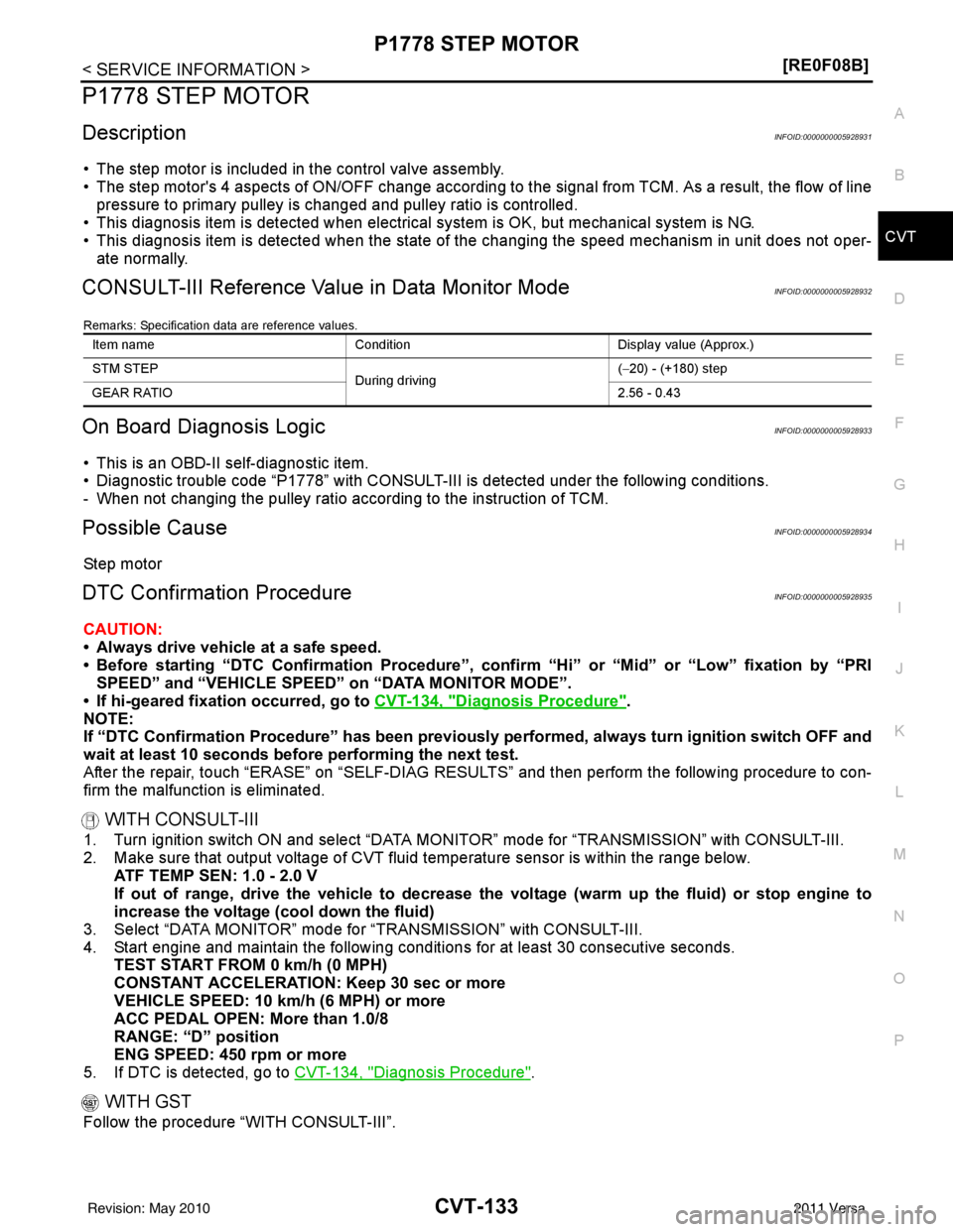
CONSULT-III Reference Val ue in Data Monitor ModeINFOID:0000000005928932
Remarks: Specification data are reference values.
On Board Diagnosis LogicINFOID:0000000005928933
• This is an OBD-II self-diagnostic item.
• Diagnostic trouble code “P1778” with CONSULT-III is detected under the following conditions.
- When not changing the pulley ratio according to the instruction of TCM.
Possible CauseINFOID:0000000005928934
Step motor
DTC Confirmation ProcedureINFOID:0000000005928935
CAUTION:
• Always drive vehicle at a safe speed.
• Before starting “DTC Confirmation Procedure”, confirm “Hi” or “Mid” or “Low” fixation by “PRI
SPEED” and “VEHICLE SPEED” on “DATA MONITOR MODE”.
• If hi-geared fixation occurred, go to CVT-134, "
Diagnosis Procedure".
NOTE:
If “DTC Confirmation Procedure” has been previously performed, always turn ignition switch OFF and
wait at least 10 seconds before performing the next test.
After the repair, touch “ERASE” on “SELF-DIAG RESULTS” and then perform the following procedure to con-
firm the malfunction is eliminated.
WITH CONSULT-III
1. Turn ignition switch ON and select “DATA MO NITOR” mode for “TRANSMISSION” with CONSULT-III.
2. Make sure that output voltage of CVT fluid temperature sensor is within the range below.
ATF TEMP SEN: 1.0 - 2.0 V
If out of range, drive the vehicle to decrease the voltage (warm up the fluid) or stop engine to
increase the voltage (c ool down the fluid)
3. Select “DATA MONITOR” mode for “TRANSMISSION” with CONSULT-III.
4. Start engine and maintain the following conditions for at least 30 consecutive seconds. TEST START FROM 0 km/h (0 MPH)
CONSTANT ACCELERATION: Keep 30 sec or more
VEHICLE SPEED: 10 km/h (6 MPH) or more
ACC PEDAL OPEN: More than 1.0/8
RANGE: “D” position
ENG SPEED: 450 rpm or more
5. If DTC is detected, go to CVT-134, "
Diagnosis Procedure".
WITH GST
Follow the procedure “WITH CONSULT-III”.
Item name Condition Display value (Approx.)
STM STEP During driving(−
20) - (+180) step
GEAR RATIO 2.56 - 0.43
Revision: May 2010 2011 Versa
Page 1211 of 3787
CVT-156
< SERVICE INFORMATION >[RE0F08B]
CVT SHIFT LOCK SYSTEM
•
Selector lever can be moved from “P” position with ignition key in ON position and brake pedal
released.
• Selector lever can be moved from “P” position when ignition switch is removed from key cylinder.
SYMPTOM 2:
• Ignition key cannot be removed when sel ector lever is set to “P” position.
• Ignition key can be removed when selector lever is set to any position except “P” position.
1.CHECK KEY INTERLOCK CABLE
Check key interlock cable for damage.
OK or NG
OK >> GO TO 2.
NG >> Repair key interlock cable. Refer to AT-219, "
Removal and Installation".
2.CHECK CVT POSITION
Check CVT position. Refer to CVT-164, "
Checking of CVT Position".
OK or NG
OK >> GO TO 3.
NG >> Adjust control cable. Refer to CVT-164, "
Adjustment of CVT Position".
3.CHECK SHIFT LOCK SOLENOID AND PARK POSITION SWITCH
1. Turn ignition switch ON. (Do not start engine.)
2. Selector lever is set in “P” position.
3. Check operation sound.
OK or NG
OK >> INSPECTION END
NG - 1 >> With intelligent key: GO TO 4.
NG - 2 >> Without intelligent key: GO TO 5.
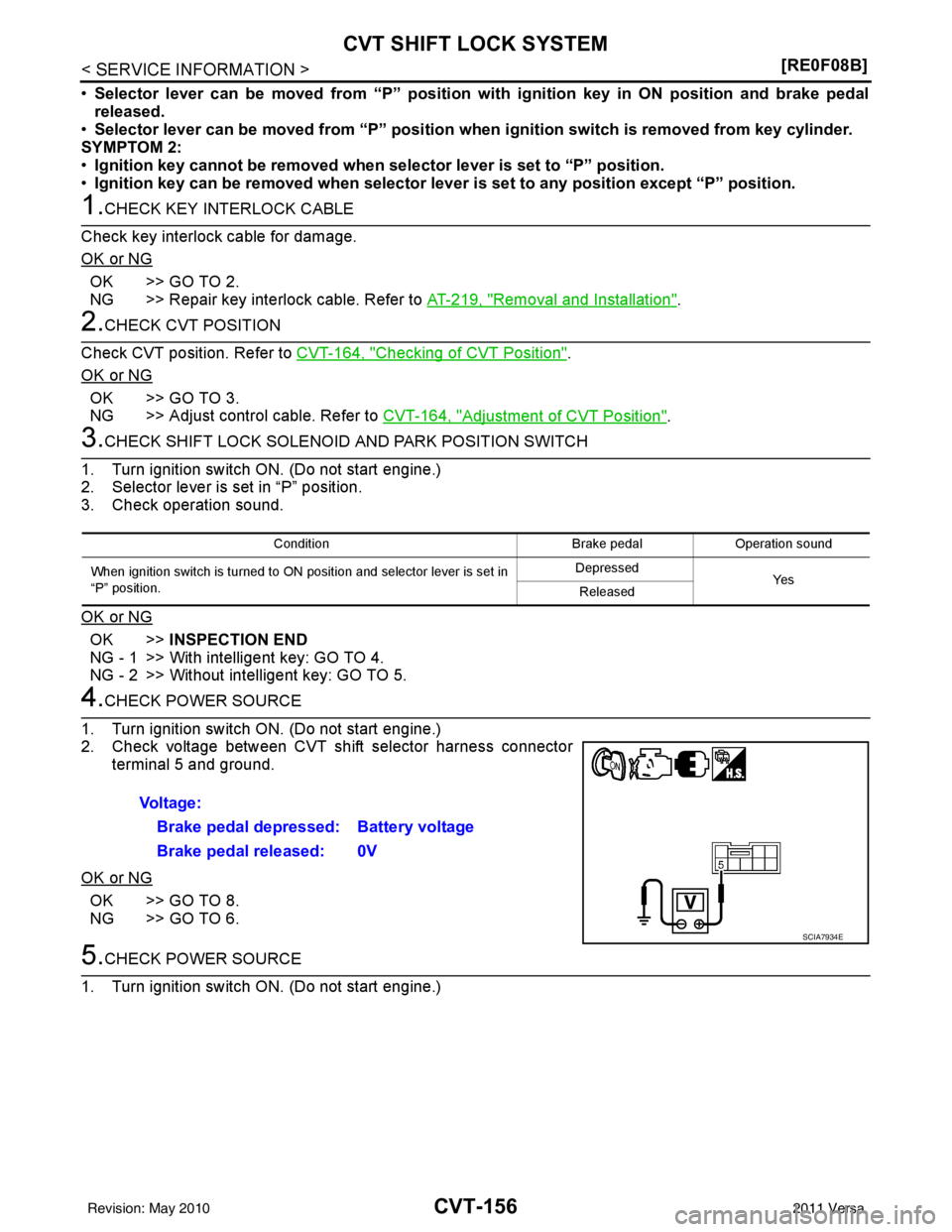
4.CHECK POWER SOURCE
1. Turn ignition switch ON. (Do not start engine.)
2. Check voltage between CVT shift selector harness connector terminal 5 and ground.
OK or NG
OK >> GO TO 8.
NG >> GO TO 6.
5.CHECK POWER SOURCE
1. Turn ignition switch ON. (Do not start engine.)
Condition Brake pedalOperation sound
When ignition switch is turned to ON position and selector lever is set in
“P” position. Depressed
Ye s
Released
Voltage:
Brake pedal depressed: Battery voltage
Brake pedal released: 0V
SCIA7934E
Revision: May 2010 2011 Versa
Page 1219 of 3787
CVT-164
< SERVICE INFORMATION >[RE0F08B]
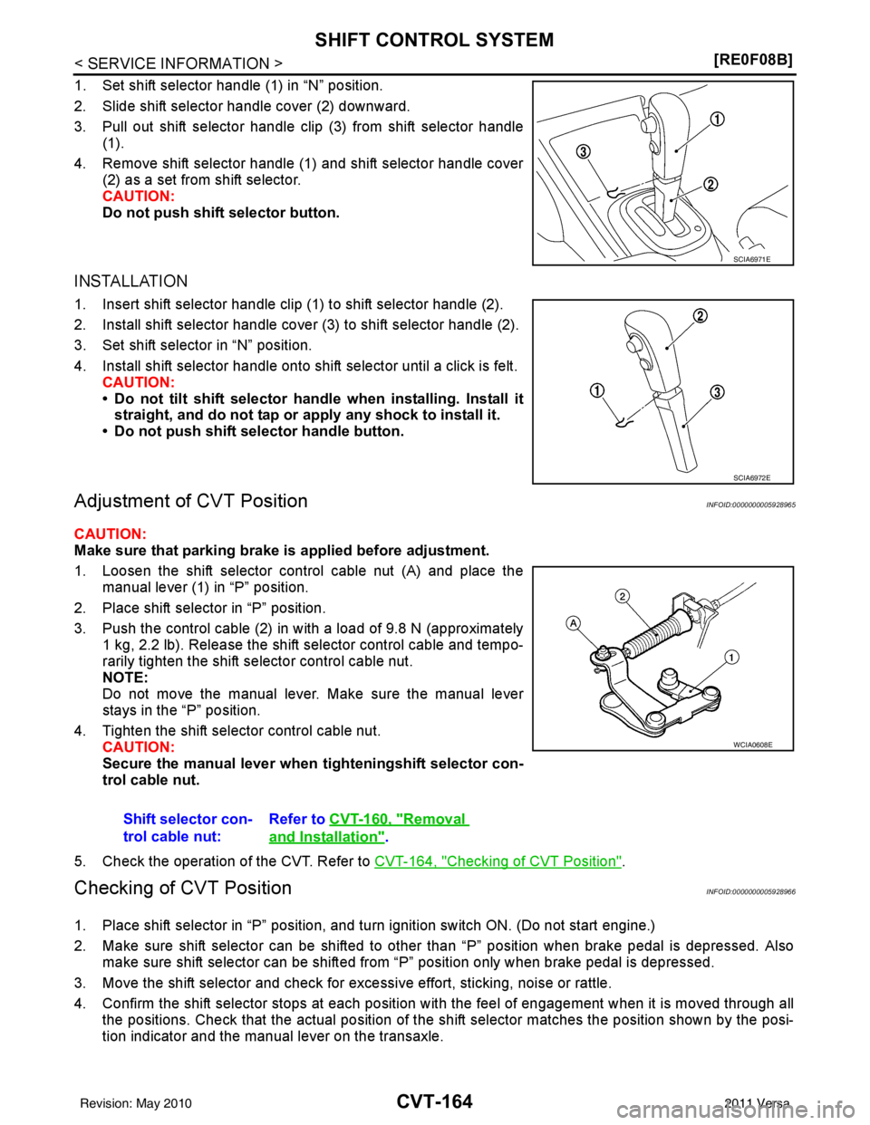
SHIFT CONTROL SYSTEM
1. Set shift selector handle (1) in “N” position.
2. Slide shift selector handle cover (2) downward.
3. Pull out shift selector handle clip (3) from shift selector handle
(1).
4. Remove shift selector handle (1) and shift selector handle cover (2) as a set from shift selector.
CAUTION:
Do not push shift selector button.
INSTALLATION
1. Insert shift selector handle clip (1) to shift selector handle (2).
2. Install shift selector handle cover (3) to shift selector handle (2).
3. Set shift selector in “N” position.
4. Install shift selector handle onto shift selector until a click is felt.
CAUTION:
• Do not tilt shift selector hand le when installing. Install it
straight, and do not tap or apply any shock to install it.
• Do not push shift selector handle button.
Adjustment of CVT PositionINFOID:0000000005928965
CAUTION:
Make sure that parking brake is applied before adjustment.
1. Loosen the shift selector control cable nut (A) and place the manual lever (1) in “P” position.
2. Place shift selector in “P” position.
3. Push the control cable (2) in with a load of 9.8 N (approximately 1 kg, 2.2 lb). Release the shift selector control cable and tempo-
rarily tighten the shift selector control cable nut.
NOTE:
Do not move the manual lever. Make sure the manual lever
stays in the “P” position.
4. Tighten the shift selector control cable nut. CAUTION:
Secure the manual lever when tighteningshift selector con-
trol cable nut.
5. Check the operation of the CVT. Refer to CVT-164, "
Checking of CVT Position".
Checking of CVT PositionINFOID:0000000005928966
1. Place shift selector in “P” position, and turn ignition switch ON. (Do not start engine.)
2. Make sure shift selector can be shifted to other than “P” position when brake pedal is depressed. Also
make sure shift selector can be shifted from “P” position only when brake pedal is depressed.
3. Move the shift selector and check for excessive effort, sticking, noise or rattle.
4. Confirm the shift selector stops at each position with the feel of engagement when it is moved through all
the positions. Check that the actual position of the shift selector matches the position shown by the posi-
tion indicator and the manual lever on the transaxle.
SCIA6971E
SCIA6972E
Shift selector con-
trol cable nut: Refer to
CVT-160, "Removal
and Installation".
WCIA0608E
Revision: May 2010 2011 Versa