NISSAN X-TRAIL 2001 Service Repair Manual
Manufacturer: NISSAN, Model Year: 2001, Model line: X-TRAIL, Model: NISSAN X-TRAIL 2001Pages: 3833, PDF Size: 39.49 MB
Page 1961 of 3833
PREPARATION
CL-3
D
E
F
G
H
I
J
K
L
MA
B
CL
PREPARATIONPFP:00002
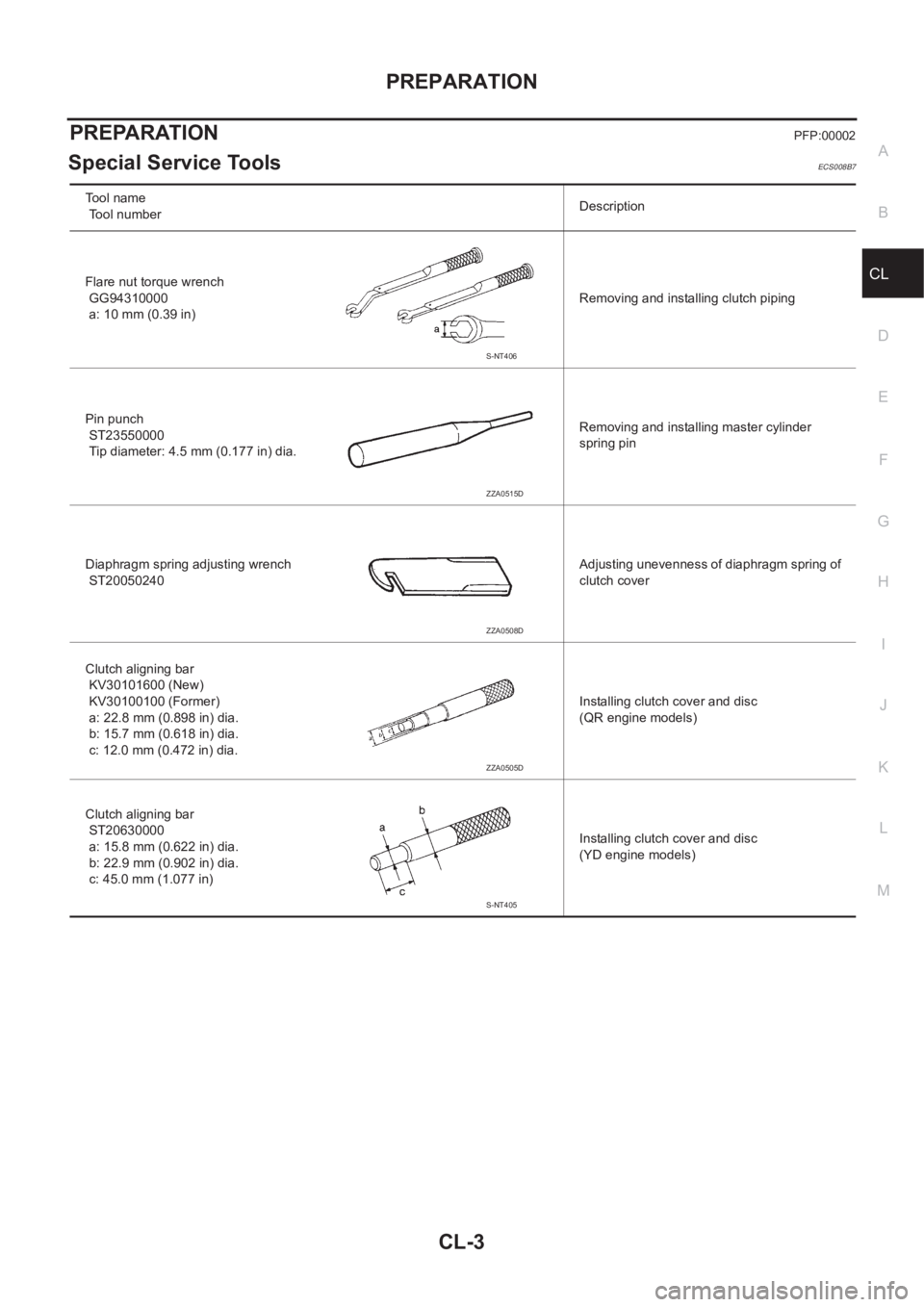
Special Service ToolsECS008B7
Tool name
Tool numberDescription
Flare nut torque wrench
GG94310000
a: 10 mm (0.39 in)Removing and installing clutch piping
Pin punch
ST23550000
Tip diameter: 4.5 mm (0.177 in) dia.Removing and installing master cylinder
spring pin
Diaphragm spring adjusting wrench
ST20050240Adjusting unevenness of diaphragm spring of
clutch cover
Clutch aligning bar
KV30101600 (New)
KV30100100 (Former)
a: 22.8 mm (0.898 in) dia.
b: 15.7 mm (0.618 in) dia.
c: 12.0 mm (0.472 in) dia.Installing clutch cover and disc
(QR engine models)
Clutch aligning bar
ST20630000
a: 15.8 mm (0.622 in) dia.
b: 22.9 mm (0.902 in) dia.
c: 45.0 mm (1.077 in)Installing clutch cover and disc
(YD engine models)
S-NT406
ZZA0515D
ZZA0508D
ZZA0505D
S-NT405
Page 1962 of 3833
CL-4
NOISE, VIBRATION, AND HARSHNESS (NVH) TROUBLESHOOTING
NOISE, VIBRATION, AND HARSHNESS (NVH) TROUBLESHOOTING
PFP:00003
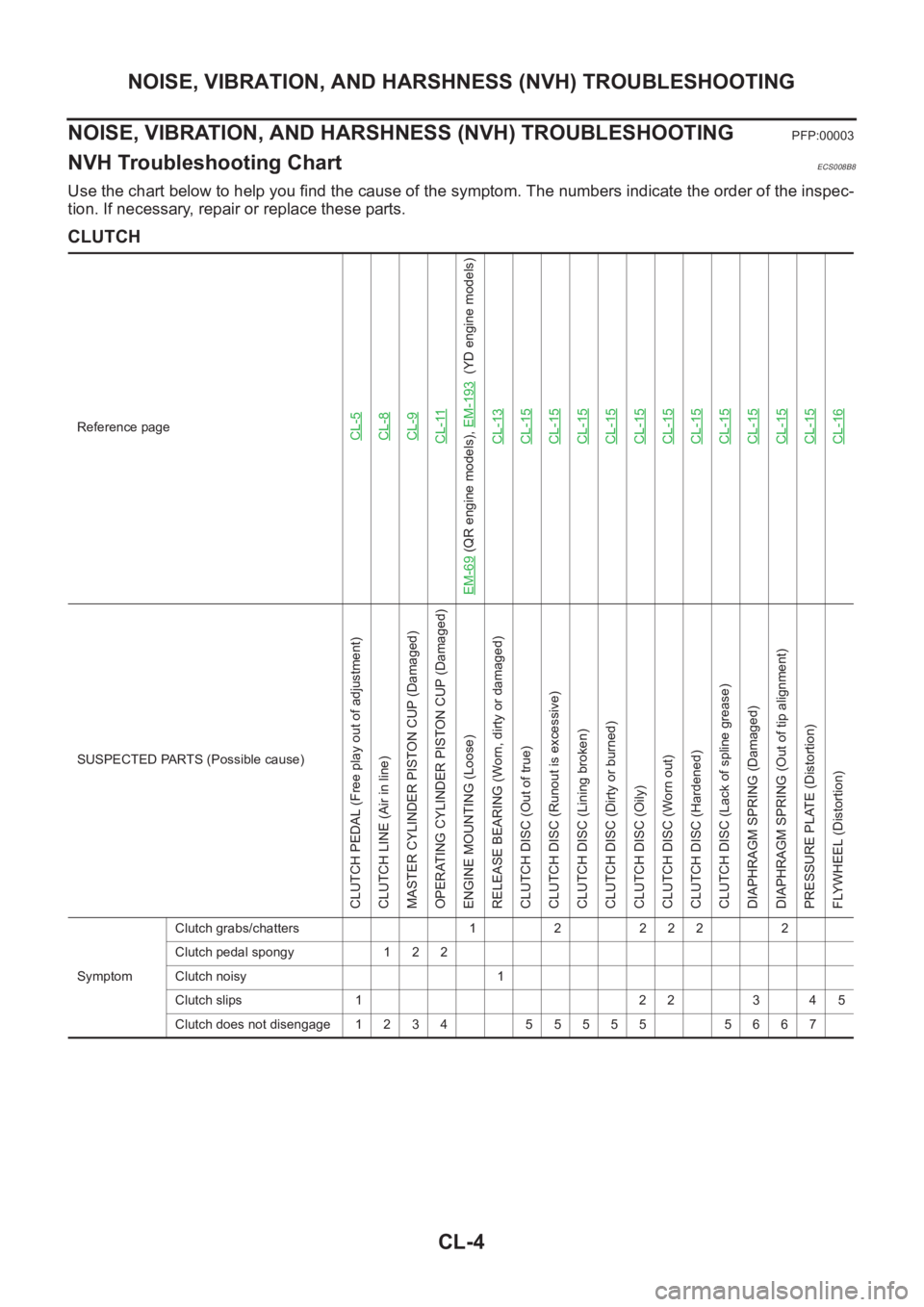
NVH Troubleshooting ChartECS008B8
Use the chart below to help you find the cause of the symptom. The numbers indicate the order of the inspec-
tion. If necessary, repair or replace these parts.
CLUTCH
Reference pageCL-5CL-8CL-9CL-11
EM-69
(QR engine models), EM-193
(YD engine models)
CL-13
CL-15CL-15CL-15CL-15CL-15CL-15CL-15CL-15CL-15CL-15CL-15CL-16
SUSPECTED PARTS (Possible cause)
CLUTCH PEDAL (Free play out of adjustment)
CLUTCH LINE (Air in line)
MASTER CYLINDER PISTON CUP (Damaged)
OPERATING CYLINDER PISTON CUP (Damaged)
ENGINE MOUNTING (Loose)
RELEASE BEARING (Worn, dirty or damaged)
CLUTCH DISC (Out of true)
CLUTCH DISC (Runout is excessive)
CLUTCH DISC (Lining broken)
CLUTCH DISC (Dirty or burned)
CLUTCH DISC (Oily)
CLUTCH DISC (Worn out)
CLUTCH DISC (Hardened)
CLUTCH DISC (Lack of spline grease)
DIAPHRAGM SPRING (Damaged)
DIAPHRAGM SPRING (Out of tip alignment)
PRESSURE PLATE (Distortion)
FLYWHEEL (Distortion)
SymptomClutch grabs/chatters 1 2 2 2 2 2
Clutch pedal spongy 1 2 2
Clutch noisy 1
Clutch slips 1 2 2 3 4 5
Clutch does not disengage 1 2 3 4 5 5 5 5 5 5 6 6 7
Page 1963 of 3833
CLUTCH PEDAL
CL-5
D
E
F
G
H
I
J
K
L
MA
B
CL
CLUTCH PEDALPFP:46540
On-Vehicle Inspection and AdjustmentECS001WB
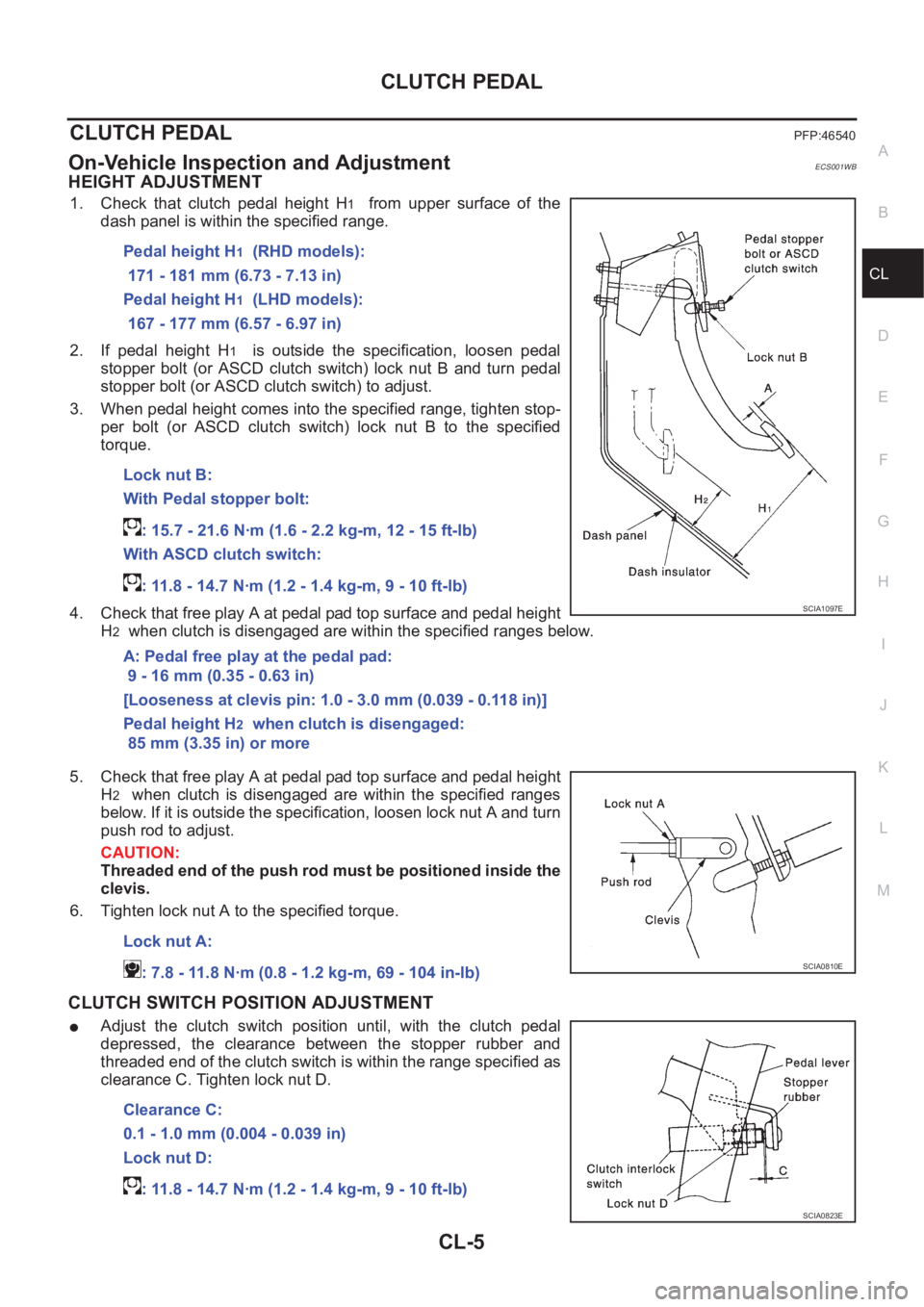
HEIGHT ADJUSTMENT
1. Check that clutch pedal height H1 from upper surface of the
dash panel is within the specified range.
2. If pedal height H
1 is outside the specification, loosen pedal
stopper bolt (or ASCD clutch switch) lock nut B and turn pedal
stopper bolt (or ASCD clutch switch) to adjust.
3. When pedal height comes into the specified range, tighten stop-
per bolt (or ASCD clutch switch) lock nut B to the specified
torque.
4. Check that free play A at pedal pad top surface and pedal height
H
2 when clutch is disengaged are within the specified ranges below.
5. Check that free play A at pedal pad top surface and pedal height
H
2 when clutch is disengaged are within the specified ranges
below. If it is outside the specification, loosen lock nut A and turn
push rod to adjust.
CAUTION:
Threaded end of the push rod must be positioned inside the
clevis.
6. Tighten lock nut A to the specified torque.
CLUTCH SWITCH POSITION ADJUSTMENT
●Adjust the clutch switch position until, with the clutch pedal
depressed, the clearance between the stopper rubber and
threaded end of the clutch switch is within the range specified as
clearance C. Tighten lock nut D.Pedal height H
1 (RHD models):
171 - 181 mm (6.73 - 7.13 in)
Pedal height H
1 (LHD models):
167 - 177 mm (6.57 - 6.97 in)
Lock nut B:
With Pedal stopper bolt:
: 15.7 - 21.6 N·m (1.6 - 2.2 kg-m, 12 - 15 ft-lb)
With ASCD clutch switch:
: 11.8 - 14.7 N·m (1.2 - 1.4 kg-m, 9 - 10 ft-lb)
A: Pedal free play at the pedal pad:
9 - 16 mm (0.35 - 0.63 in)
[Looseness at clevis pin: 1.0 - 3.0 mm (0.039 - 0.118 in)]
Pedal height H
2 when clutch is disengaged:
85 mm (3.35 in) or more
SCIA1097E
Lock nut A:
: 7.8 - 11.8 N·m (0.8 - 1.2 kg-m, 69 - 104 in-lb)
SCIA0810E
Clearance C:
0.1 - 1.0 mm (0.004 - 0.039 in)
Lock nut D:
: 11.8 - 14.7 N·m (1.2 - 1.4 kg-m, 9 - 10 ft-lb)
SCIA0823E
Page 1964 of 3833
CL-6
CLUTCH PEDAL
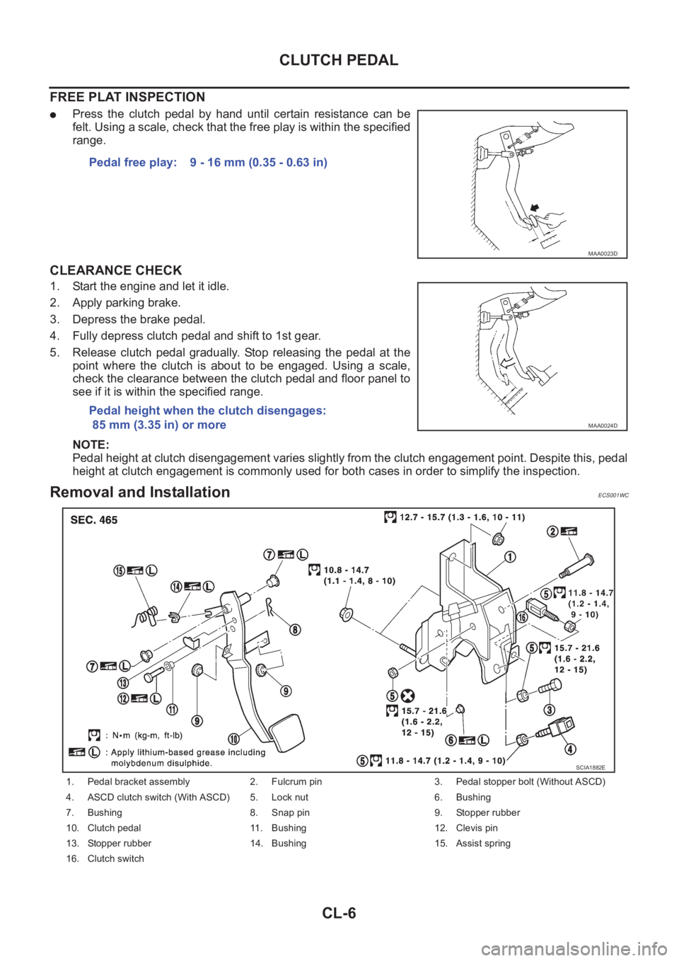
FREE PLAT INSPECTION
●Press the clutch pedal by hand until certain resistance can be
felt. Using a scale, check that the free play is within the specified
range.
CLEARANCE CHECK
1. Start the engine and let it idle.
2. Apply parking brake.
3. Depress the brake pedal.
4. Fully depress clutch pedal and shift to 1st gear.
5. Release clutch pedal gradually. Stop releasing the pedal at the
point where the clutch is about to be engaged. Using a scale,
check the clearance between the clutch pedal and floor panel to
see if it is within the specified range.
NOTE:
Pedal height at clutch disengagement varies slightly from the clutch engagement point. Despite this, pedal
height at clutch engagement is commonly used for both cases in order to simplify the inspection.
Removal and InstallationECS001WC
Pedal free play: 9 - 16 mm (0.35 - 0.63 in)
MAA0023D
Pedal height when the clutch disengages:
85 mm (3.35 in) or more
MAA0024D
1. Pedal bracket assembly 2. Fulcrum pin 3. Pedal stopper bolt (Without ASCD)
4. ASCD clutch switch (With ASCD) 5. Lock nut 6. Bushing
7. Bushing 8. Snap pin 9. Stopper rubber
10. Clutch pedal 11. Bushing 12. Clevis pin
13. Stopper rubber 14. Bushing 15. Assist spring
16. Clutch switch
SCIA1882E
Page 1965 of 3833
CLUTCH PEDAL
CL-7
D
E
F
G
H
I
J
K
L
MA
B
CL
NOTE:
Install clutch pedal assembly and adjust the pedal height. Tighten pedal stopper bolt (or ASCD clutch switch)
to the specified torque.
INSPECTION AFTER REMOVAL
●Check clutch pedal for bend, damage, or a cracked weld. If bend, damage, or a cracked weld is found,
replace the clutch pedal.
●Check assist spring for settling. If settling is found, replace the assist spring.
Page 1966 of 3833
CL-8
CLUTCH FLUID
CLUTCH FLUID
PFP:00017
Air Bleeding ProcedureECS008B9
CAUTION:
●Monitor fluid level in the reservoir tank to make sure it does
not empty.
●Do not spill clutch fluid onto painted surfaces. If it spills,
wipe up immediately and wash the affected area with water.
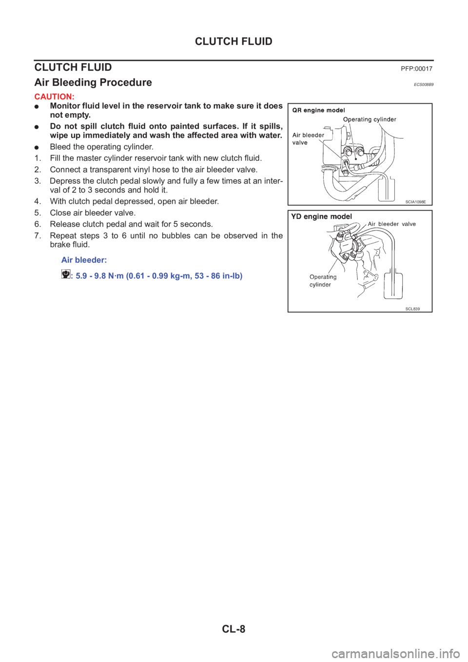
●Bleed the operating cylinder.
1. Fill the master cylinder reservoir tank with new clutch fluid.
2. Connect a transparent vinyl hose to the air bleeder valve.
3. Depress the clutch pedal slowly and fully a few times at an inter-
val of 2 to 3 seconds and hold it.
4. With clutch pedal depressed, open air bleeder.
5. Close air bleeder valve.
6. Release clutch pedal and wait for 5 seconds.
7. Repeat steps 3 to 6 until no bubbles can be observed in the
brake fluid.
Air bleeder:
: 5.9 - 9.8 N·m (0.61 - 0.99 kg-m, 53 - 86 in-lb)
SCIA1098E
SCL839
Page 1967 of 3833
CLUTCH MASTER CYLINDER
CL-9
D
E
F
G
H
I
J
K
L
MA
B
CL
CLUTCH MASTER CYLINDERPFP:30610
Removal and InstallationECS008BA
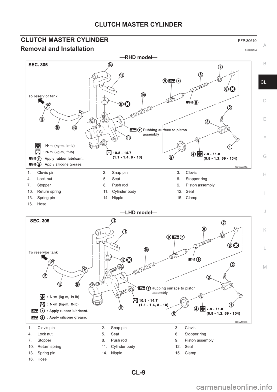
—RHD model—
—LHD model—
SCIA0324E
1. Clevis pin 2. Snap pin 3. Clevis
4. Lock nut 5. Seat 6. Stopper ring
7. Stopper 8. Push rod 9. Piston assembly
10. Return spring 11. Cylinder body 12. Seal
13. Spring pin 14. Nipple 15. Clamp
16. Hose
SCIA1099E
1. Clevis pin 2. Snap pin 3. Clevis
4. Lock nut 5. Seat 6. Stopper ring
7. Stopper 8. Push rod 9. Piston assembly
10. Return spring 11. Cylinder body 12. Seal
13. Spring pin 14. Nipple 15. Clamp
16. Hose
Page 1968 of 3833
CL-10
CLUTCH MASTER CYLINDER
REMOVAL
1. Using one of the following methods, remove hose from the nipple.
●Drain clutch fluid from reservoir tank and remove hose.
●Remove hose from the nipple. Immediately plug hose and reservoir tank to prevent clutch fluid from
dripping.
CAUTION:
Do not spill clutch fluid onto painted surfaces. If it spills, wipe up immediately and wash the
affected area with water.
2. Using a flare nut wrench, remove clutch tube.
3. Remove snap pin and clevis pin on clevis in passenger compartment to separate clutch pedal.
4. First remove the mounting nuts on the master cylinder assembly, and then the master cylinder assembly
from the vehicle.
INSTALLATION
1. Connect clutch tube to master cylinder assembly and temporarily tighten flare nut.
2. Install master cylinder assembly and tighten mounting nut to the specified torque.
3. Using a flare nut torque wrench, tighten clutch tube flare nut to the specified torque.
4. Attach clevis of the clevis pin to the clutch pedal.
5. Attach snap pin to the clevis pin.
6. Install hose to the nipple.
7. After completing this procedure, inspect and adjust pedal height and then bleed the clutch tube.
●Refer to CL-5, "On-Vehicle Inspection and Adjustment" , CL-8, "Air Bleeding Procedure" .
Disassembly and AssemblyECS008BB
DISASSEMBLY
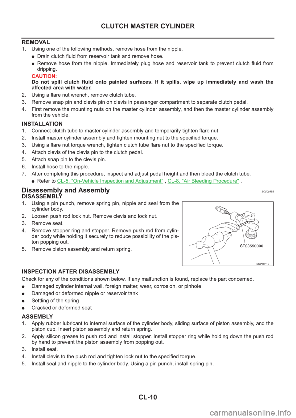
1. Using a pin punch, remove spring pin, nipple and seal from the
cylinder body.
2. Loosen push rod lock nut. Remove clevis and lock nut.
3. Remove seat.
4. Remove stopper ring and stopper. Remove push rod from cylin-
der body while holding it securely to reduce possibility of the pis-
ton popping out.
5. Remove piston assembly and return spring.
INSPECTION AFTER DISASSEMBLY
Check for any of the conditions shown below. If any malfunction is found, replace the part concerned.
●Damaged cylinder internal wall, foreign matter, wear, corrosion, or pinhole
●Damaged or deformed nipple or reservoir tank
●Settling of the spring
●Cracked or deformed seat
ASSEMBLY
1. Apply rubber lubricant to internal surface of the cylinder body, sliding surface of piston assembly, and the
piston cup. Insert piston assembly and return spring.
2. Apply silicon grease to push rod and install stopper. Install stopper ring while holding down the push rod
by hand to prevent the piston assembly from popping out.
3. Install seat.
4. Install clevis to the push rod and tighten lock nut to the specified torque.
5. Install seal and nipple to the cylinder body. Using a pin punch, install spring pin.
SCIA0811E
Page 1969 of 3833
OPERATING CYLINDER
CL-11
D
E
F
G
H
I
J
K
L
MA
B
CL
OPERATING CYLINDERPFP:30620
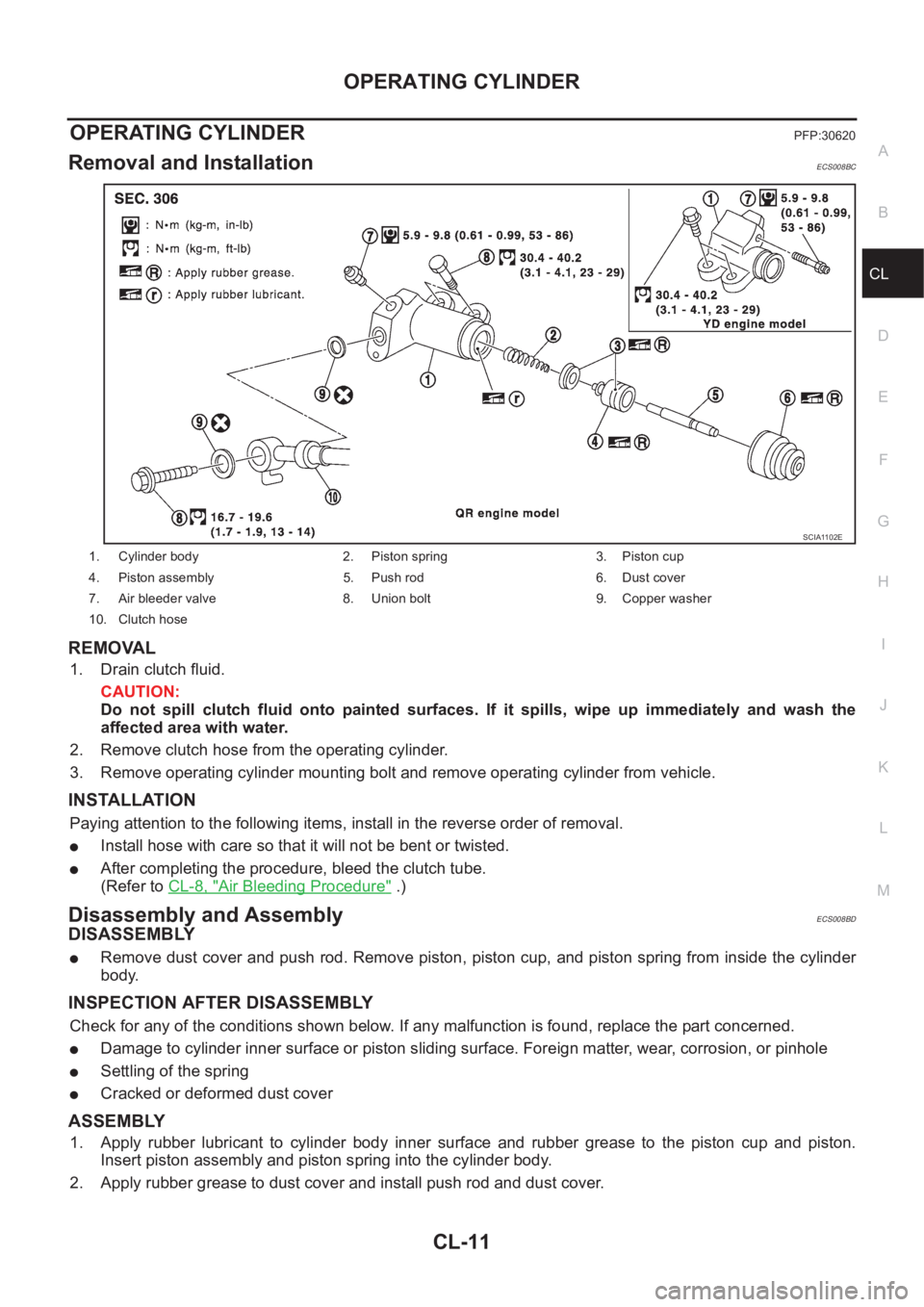
Removal and InstallationECS008BC
REMOVAL
1. Drain clutch fluid.
CAUTION:
Do not spill clutch fluid onto painted surfaces. If it spills, wipe up immediately and wash the
affected area with water.
2. Remove clutch hose from the operating cylinder.
3. Remove operating cylinder mounting bolt and remove operating cylinder from vehicle.
INSTALLATION
Paying attention to the following items, install in the reverse order of removal.
●Install hose with care so that it will not be bent or twisted.
●After completing the procedure, bleed the clutch tube.
(Refer to CL-8, "
Air Bleeding Procedure" .)
Disassembly and AssemblyECS008BD
DISASSEMBLY
●Remove dust cover and push rod. Remove piston, piston cup, and piston spring from inside the cylinder
body.
INSPECTION AFTER DISASSEMBLY
Check for any of the conditions shown below. If any malfunction is found, replace the part concerned.
●Damage to cylinder inner surface or piston sliding surface. Foreign matter, wear, corrosion, or pinhole
●Settling of the spring
●Cracked or deformed dust cover
ASSEMBLY
1. Apply rubber lubricant to cylinder body inner surface and rubber grease to the piston cup and piston.
Insert piston assembly and piston spring into the cylinder body.
2. Apply rubber grease to dust cover and install push rod and dust cover.
1. Cylinder body 2. Piston spring 3. Piston cup
4. Piston assembly 5. Push rod 6. Dust cover
7. Air bleeder valve 8. Union bolt 9. Copper washer
10. Clutch hose
SCIA1102E
Page 1970 of 3833
CL-12
CLUTCH PIPING
CLUTCH PIPING
PFP:30650
Removal and InstallationECS008BE
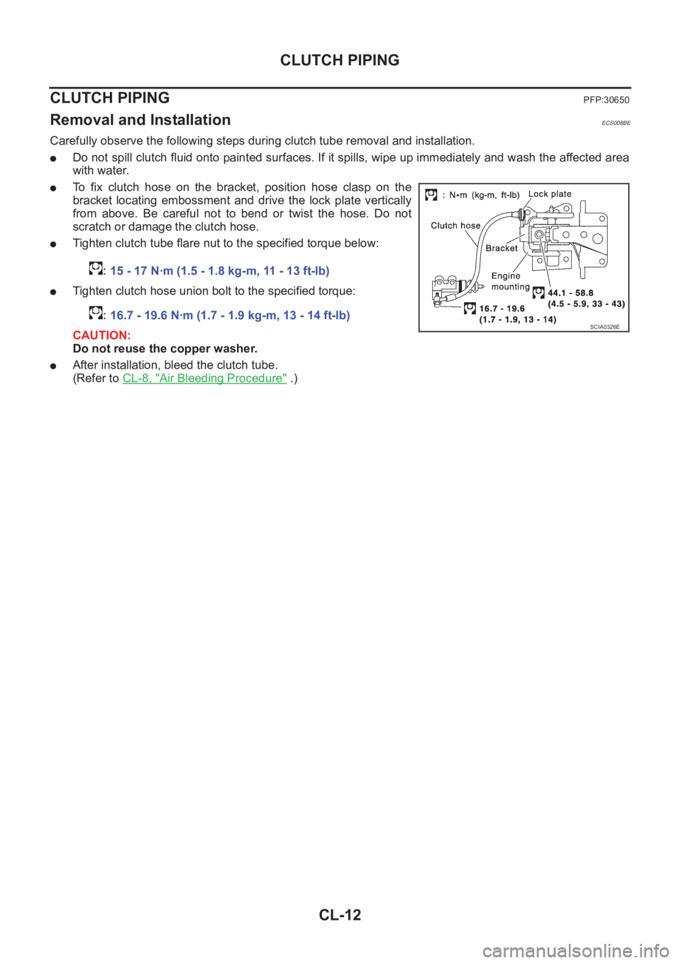
Carefully observe the following steps during clutch tube removal and installation.
●Do not spill clutch fluid onto painted surfaces. If it spills, wipe up immediately and wash the affected area
with water.
●To fix clutch hose on the bracket, position hose clasp on the
bracket locating embossment and drive the lock plate vertically
from above. Be careful not to bend or twist the hose. Do not
scratch or damage the clutch hose.
●Tighten clutch tube flare nut to the specified torque below:
●Tighten clutch hose union bolt to the specified torque:
CAUTION:
Do not reuse the copper washer.
●After installation, bleed the clutch tube.
(Refer to CL-8, "
Air Bleeding Procedure" .) : 15 - 17 N·m (1.5 - 1.8 kg-m, 11 - 13 ft-lb)
: 16.7 - 19.6 N·m (1.7 - 1.9 kg-m, 13 - 14 ft-lb)
SCIA0326E