glove box NISSAN X-TRAIL 2001 Service Repair Manual
[x] Cancel search | Manufacturer: NISSAN, Model Year: 2001, Model line: X-TRAIL, Model: NISSAN X-TRAIL 2001Pages: 3833, PDF Size: 39.49 MB
Page 437 of 3833
TROUBLE DIAGNOSIS
EC-87
[QR25(WITH EURO-OBD)]
C
D
E
F
G
H
I
J
K
L
MA
EC
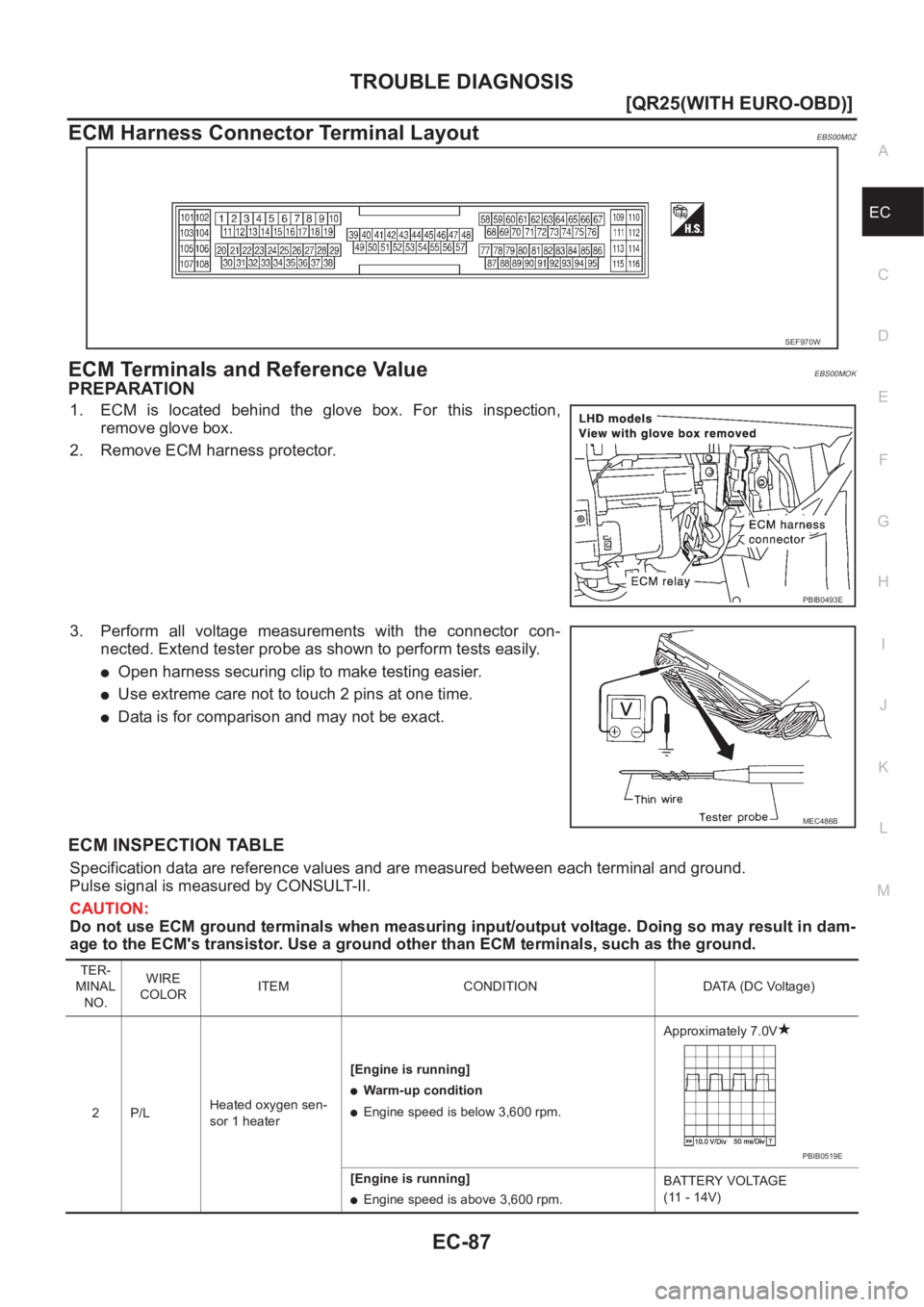
ECM Harness Connector Terminal LayoutEBS00M0Z
ECM Terminals and Reference ValueEBS00MOK
PREPARATION
1. ECM is located behind the glove box. For this inspection,
remove glove box.
2. Remove ECM harness protector.
3. Perform all voltage measurements with the connector con-
nected. Extend tester probe as shown to perform tests easily.
●Open harness securing clip to make testing easier.
●Use extreme care not to touch 2 pins at one time.
●Data is for comparison and may not be exact.
ECM INSPECTION TABLE
Specification data are reference values and are measured between each terminal and ground.
Pulse signal is measured by CONSULT-II.
CAUTION:
Do not use ECM ground terminals when measuring input/output voltage. Doing so may result in dam-
age to the ECM's transistor. Use a ground other than ECM terminals, such as the ground.
SEF970W
PBIB0493E
MEC486B
TER-
MINAL
NO.WIRE
COLORITEM CONDITION DATA (DC Voltage)
2P/LHeated oxygen sen-
sor 1 heater[Engine is running]
●Warm-up condition
●Engine speed is below 3,600 rpm.Approximately 7.0V
[Engine is running]
●Engine speed is above 3,600 rpm.BATTERY VOLTAGE
(11 - 14V)
PBIB0519E
Page 829 of 3833
TROUBLE DIAGNOSIS
EC-479
[QR25(WITHOUT EURO-OBD)]
C
D
E
F
G
H
I
J
K
L
MA
EC
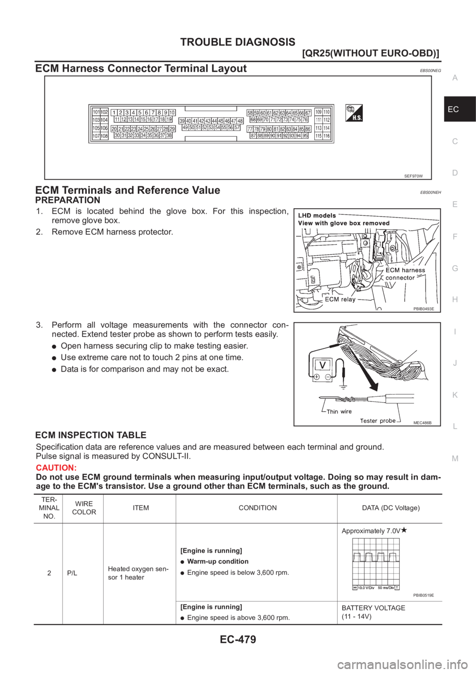
ECM Harness Connector Terminal LayoutEBS00NEG
ECM Terminals and Reference ValueEBS00NEH
PREPARATION
1. ECM is located behind the glove box. For this inspection,
remove glove box.
2. Remove ECM harness protector.
3. Perform all voltage measurements with the connector con-
nected. Extend tester probe as shown to perform tests easily.
●Open harness securing clip to make testing easier.
●Use extreme care not to touch 2 pins at one time.
●Data is for comparison and may not be exact.
ECM INSPECTION TABLE
Specification data are reference values and are measured between each terminal and ground.
Pulse signal is measured by CONSULT-II.
CAUTION:
Do not use ECM ground terminals when measuring input/output voltage. Doing so may result in dam-
age to the ECM's transistor. Use a ground other than ECM terminals, such as the ground.
SEF970W
PBIB0493E
MEC486B
TER-
MINAL
NO.WIRE
COLORITEM CONDITION DATA (DC Voltage)
2P/LHeated oxygen sen-
sor 1 heater[Engine is running]
●Warm-up condition
●Engine speed is below 3,600 rpm.Approximately 7.0V
[Engine is running]
●Engine speed is above 3,600 rpm.BATTERY VOLTAGE
(11 - 14V)
PBIB0519E
Page 1169 of 3833
TROUBLE DIAGNOSIS
EC-819
[QR20(WITH EURO-OBD)]
C
D
E
F
G
H
I
J
K
L
MA
EC
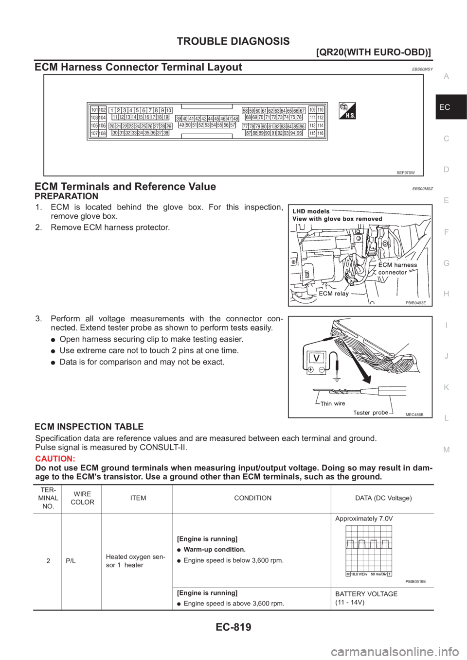
ECM Harness Connector Terminal LayoutEBS00MSY
ECM Terminals and Reference ValueEBS00MSZ
PREPARATION
1. ECM is located behind the glove box. For this inspection,
remove glove box.
2. Remove ECM harness protector.
3. Perform all voltage measurements with the connector con-
nected. Extend tester probe as shown to perform tests easily.
●Open harness securing clip to make testing easier.
●Use extreme care not to touch 2 pins at one time.
●Data is for comparison and may not be exact.
ECM INSPECTION TABLE
Specification data are reference values and are measured between each terminal and ground.
Pulse signal is measured by CONSULT-II.
CAUTION:
Do not use ECM ground terminals when measuring input/output voltage. Doing so may result in dam-
age to the ECM's transistor. Use a ground other than ECM terminals, such as the ground.
SEF970W
PBIB0493E
MEC486B
TER-
MINAL
NO.WIRE
COLORITEM CONDITION DATA (DC Voltage)
2P/LHeated oxygen sen-
sor 1 heater[Engine is running]
●Warm-up condition.
●Engine speed is below 3,600 rpm.Approximately 7.0V
[Engine is running]
●Engine speed is above 3,600 rpm.BATTERY VOLTAGE
(11 - 14V)
PBIB0519E
Page 1516 of 3833
EC-1166
[QR20(WITHOUT EURO-OBD)]
TROUBLE DIAGNOSIS
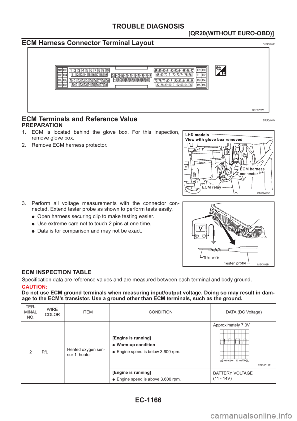
ECM Harness Connector Terminal Layout
EBS00N43
ECM Terminals and Reference ValueEBS00N44
PREPARATION
1. ECM is located behind the glove box. For this inspection,
remove glove box.
2. Remove ECM harness protector.
3. Perform all voltage measurements with the connector con-
nected. Extend tester probe as shown to perform tests easily.
●Open harness securing clip to make testing easier.
●Use extreme care not to touch 2 pins at one time.
●Data is for comparison and may not be exact.
ECM INSPECTION TABLE
Specification data are reference values and are measured between each terminal and body ground.
CAUTION:
Do not use ECM ground terminals when measuring input/output voltage. Doing so may result in dam-
age to the ECM's transistor. Use a ground other than ECM terminals, such as the ground.
SEF970W
PBIB0493E
MEC486B
TER-
MINAL
NO.WIRE
COLORITEM CONDITION DATA (DC Voltage)
2P/LHeated oxygen sen-
sor 1 heater[Engine is running]
●Warm-up condition
●Engine speed is below 3,600 rpm.Approximately 7.0V
[Engine is running]
●Engine speed is above 3,600 rpm.BATTERY VOLTAGE
(11 - 14V)
PBIB0519E
Page 1775 of 3833
TROUBLE DIAGNOSIS
EC-1425
[YD]
C
D
E
F
G
H
I
J
K
L
MA
EC
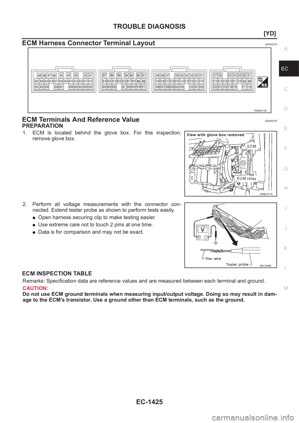
ECM Harness Connector Terminal LayoutEBS00374
ECM Terminals And Reference ValueEBS00375
PREPARATION
1. ECM is located behind the glove box. For this inspection,
remove glove box.
2. Perform all voltage measurements with the connector con-
nected. Extend tester probe as shown to perform tests easily.
●Open harness securing clip to make testing easier.
●Use extreme care not to touch 2 pins at one time.
●Data is for comparison and may not be exact.
ECM INSPECTION TABLE
Remarks: Specification data are reference values and are measured between each terminal and ground.
CAUTION:
Do not use ECM ground terminals when measuring input/output voltage. Doing so may result in dam-
age to the ECM's transistor. Use a ground other than ECM terminals, such as the ground.
PBIB0473E
PBIB0377E
MEC486B
Page 2826 of 3833
BRC-42
[4WD/ABS]
TROUBLE DIAGNOSIS
Using active test mode of CONSULT-II, supply current to the 4WD solenoid valve and check that the mon-
itor current becomes close to this supply current.
●The 4WDcontrol unit is normal when the difference between 4WD solenoid valve current and the monitor
current is within ±10%.
It is necessary to inspect the electronically controlled coupling assembly.
TIGHT-CORNER BRAKING SYMPTOM OCCURS WHEN THE VEHICLE IS STARTED IN AUTO
WARNING LAMP REMAIN OFF).
1. THROTTLE POSITION SENSOR AND HARNESS INSPECTION
Check accelerator pedal stroke.
OK or NG
OK >> Perform self-diagnosis again.
NG >> Malfunctioning throttle position sensor harness
4WD ACTUATOR RELAY (4WD SOLENOID ACTUATOR RELAY) TURNS ON/OFF FREQUENTLY
1. SELF-DIAGNOSIS RESULT IS 4WD ACTUATOR RELAY (4WD SOLENOID ACTUATOR RELAY) ON
ERROR AND OFF ERROR
Is self-diagnosis result [ON error and OFF error]?
OK or NG
OK >> GO TO 2.
NG >> Repair or replace as necessary.
2. 4WD ACTUATOR RELAY (4WD SOLENOID ACTUATOR RELAY) AND HARNESS INSPECTION
Is self-diagnosis result [ON error and OFF error]?
OK or NG
OK >> Perform self-diagnosis again.
NG >> Malfunctioning 4WD actuator relay (4WD solenoid actuator relay) harness
ABS Warning Lamp Does Not Illuminate. (ABS Warning Lamp Does Not Come
On When The Ignition Switch Is Turned ON.)
EFS001BP
●Replace the combination meter control unit.
ABS Warning Lamp Illuminates With Ignition ON, But Does Not Illuminates After
A Few Seconds. (ABS Warning Lamp Has Illuminated.)
EFS001BQ
1. 4WD/ABS CONTROL MODULE CONNECTOR CONNECTION INSPECTION
●Remove glove box on the passenger side and check 4WD/ABS control module connector for proper con-
nection.
Is inspection result OK?
YES >> Proceed to 2. (4WD/ABS control unit connector is properly connected.)
NO >>
●Connect the 4WD/ABS control unit connector and perform inspection again.
2. USING CONSULT, PERFORM SELF-DIAGNOSIS
●Connect the CONSULT-II and perform self-diagnosis.
Is inspection result OK?
YES >> GO TO 3. (No self-diagnosis malfunction indicated.)
NO >> Perform inspection according to the trouble codes displayed on the CONSULT-II. Refer to the
“DTC chart”. Example) Monitor value becomes Approx. 1 A for 4WD solenoid current 1 A setting.
Page 2827 of 3833
TROUBLE DIAGNOSIS
BRC-43
[4WD/ABS]
C
D
E
G
H
I
J
K
L
MA
B
BRC
3.CHECK CONTINUITY BETWEEN IGNITION SWITCH AND ABS WARNING LAMP
●Disconnect 4WD/ABS control unit connector.
●Check continuity between ignition switch and 4WD/ABS control module terminal No. 4. (Open circuit
check)
Is inspection result OK?
YES >> Continuity exists. Connect 4WD/ABS control module connector, check again.
NO >> Continuity does not exist. Check ABS warning lamp path.
4.CHECK FUSE
●Check if Fuse No.8 is working normally.
Is the check result OK?
YES >> Repair or replace the harness in between 4WD/ABS control unit and IGN.
NO >> Replace the fuse and replace again.
●If the figure of the monitor is with in ± 10% of the set value of E-TS solenoid electric current, 4WD/ABS C/
U is operating normally. Check for electric control coupling ASSY is required.
4WD Warning Lamp Does Not Illuminate With Ignition ON.EFS001BR
1.INSPECTION OF BLOWN 4WD WARNING LAMP BULB
●Remove glove box on the passenger side and disconnect the 4WD/ABS control unit connector.
●Confirm continuity between 4WD/ABS control unit connector terminals No. 3 (IGN) and No. 4 (ABS warn-
ing lamp).
Is inspection result OK?
YES >> GO TO 3. (Continuity exists.)
NO >>
●Check 4WD warning lamp harness.
●Remove meter control module assembly and check for blown 4WD warning lamp bulb.
2.4WD ACTUATOR RELAY HARNESS INSPECTION
●Open the hood and check that the 4WD relay is properly installed in the relay box.
●Confirm continuity between 4WD/ABS control unit connector terminals No. 7 (4WD warning lamp) and No.
104 (ground).
●Confirm continuity between 4WD/ABS control unit connector terminals No. 3 (IGN) and No. 18 (4WD
actuator relay).
Is inspection result OK?
YES >> Continuity exists. Connect 4WD/ABS control unit connector, check again.
NO >> Check ABS warning lamp harness.
4WD Warning Lamp Does Not Go Out Several Seconds After Engine Is Started.
(Drive Mode Indicator Lamp Goes Out.)
EFS001BS
1.USING CONSULT, PERFORM SELF-DIAGNOSIS
4WD warning lamp does not go out several seconds after the engine is started. (Drive mode indicator lamp
goes out.)
Is inspection result OK?
YES >> No malfunction detected. Perform inspection again.
NO >>
●Determine the location of the malfunction according to the result of self-diagnosis using CON-
SULT. (Malfunction is present in the 4WD system.)
●CONSULT-II does not display ABS -related trouble codes. Proceed to 2.
Page 2828 of 3833
BRC-44
[4WD/ABS]
TROUBLE DIAGNOSIS
2. 4WD/ABS CONTROL UNIT CONNECTOR CONNECTION INSPECTION
●Remove glove box on the passenger side and check 4WD/ABS control unit connector for proper connec-
tion.
Is inspection result OK?
YES >> 4WD/ABS control unit connector is properly connected.
NO >> Reconnect the 4WD/ABS control module connector properly and perform inspection again.
Heavy Tight-corner Braking Symptom Occurs When The Vehicle Is Driven In
Auto Mode And The Steering Wheel Is Turned Fully To Either Side After The
Engine Is Started.
EFS001BT
1. USING CONSULT, PERFORM OR SELF-DIAGNOSIS
Heavy tight-corner braking symptom occurs when the vehicle is driven in AUTO mode and the steering wheel
is turned fully to either side after the engine is started.
Is inspection result OK?
YES >> GO TO 2. (No self-diagnosis malfunction indicated.)
NO >> Determine the location of the malfunction according to the result of self-diagnosis using CON-
SULT-II. (Malfunction is present in the 4WD system.)
2. CHECK USING THE DATA MONITOR FUNCTION OF THE CONSULT-II
●Perform inspection by the data monitor function of the CONSULT-II.
●Check that the operation is in AUTO mode.
●Measure voltage when the accelerator pedal is not depressed. (Accelerator pedal not depressed: Approx.
0.5V or lower)
●Measure the current supplied to the E-TS solenoid valve. (Accelerator pedal not depressed: Approx. 0A)
Is inspection result OK?
YES >> GO TO 3. (No self-diagnosis malfunction indicated.)
NO >>
●Not in AUTO mode. GO TO 3.
●Voltage when accelerator pedal is not depressed is higher than approximately 0.5V.
●E-TS solenoid valve current when accelerator pedal is not depressed is other than 0A.
●Countermeasure: Keep the vehicle idling for approximately 15 minutes before checking again.
(Voltage when accelerator pedal is not depressed will be automatically reset to zero during this
period.)
Page 2832 of 3833
BRC-48
[4WD/ABS]
4WD/ABS CONTROL UNIT
4WD/ABS CONTROL UNIT
PFP:47660
Removal and InstallationEFS002F7
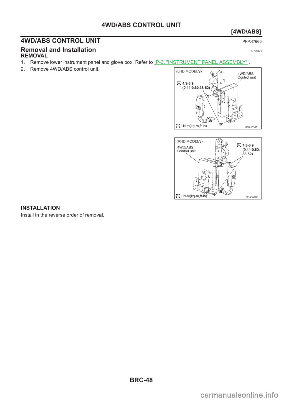
REMOVAL
1. Remove lower instrument panel and glove box. Refer to IP-3, "INSTRUMENT PANEL ASSEMBLY" .
2. Remove 4WD/ABS control unit.
INSTALLATION
Install in the reverse order of removal.
SFIA1038E
SFIA1039E
Page 3037 of 3833
FRONT PASSENGER AIR BAG MODULE
SRS-35
C
D
E
F
G
I
J
K
L
MA
B
SRS
FRONT PASSENGER AIR BAG MODULEPFP:K8515
Removal and InstallationEHS000D9
REMOVAL
CAUTION:
●Before servicing SRS, turn the ignition switch off, disconnect both battery cables and wait at least
3 minutes.
●Always work from the side of or under front passenger air bag module.
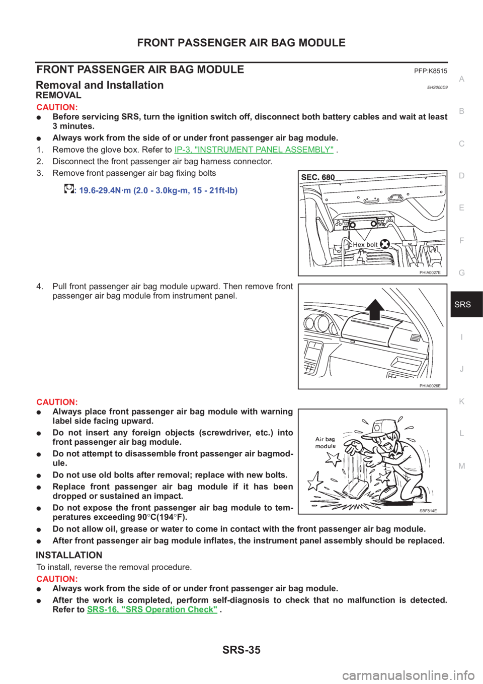
1. Remove the glove box. Refer to IP-3, "
INSTRUMENT PANEL ASSEMBLY" .
2. Disconnect the front passenger air bag harness connector.
3. Remove front passenger air bag fixing bolts
4. Pull front passenger air bag module upward. Then remove front
passenger air bag module from instrument panel.
CAUTION:
●Always place front passenger air bag module with warning
label side facing upward.
●Do not insert any foreign objects (screwdriver, etc.) into
front passenger air bag module.
●Do not attempt to disassemble front passenger air bagmod-
ule.
●Do not use old bolts after removal; replace with new bolts.
●Replace front passenger air bag module if it has been
dropped or sustained an impact.
●Do not expose the front passenger air bag module to tem-
peratures exceeding 90°C(194°F).
●Do not allow oil, grease or water to come in contact with the front passenger air bag module.
●After front passenger air bag module inflates, the instrument panel assembly should be replaced.
INSTALLATION
To install, reverse the removal procedure.
CAUTION:
●Always work from the side of or under front passenger air bag module.
●After the work is completed, perform self-diagnosis to check that no malfunction is detected.
Refer to SRS-16, "
SRS Operation Check" . : 19.6-29.4N·m (2.0 - 3.0kg-m, 15 - 21ft-lb)
PHIA0027E
PHIA0026E
SBF814E