window NISSAN X-TRAIL 2001 Service Owner's Manual
[x] Cancel search | Manufacturer: NISSAN, Model Year: 2001, Model line: X-TRAIL, Model: NISSAN X-TRAIL 2001Pages: 3833, PDF Size: 39.49 MB
Page 1090 of 3833
EC-740
[QR25(WITHOUT EURO-OBD)]
ELECTRICAL LOAD SIGNAL
Diagnostic Procedure
EBS00NLA
1. INSPECTION START
Do you have CONSULT-II?
Ye s o r N o
Yes >> GO TO 2.
No >> GO TO 5.
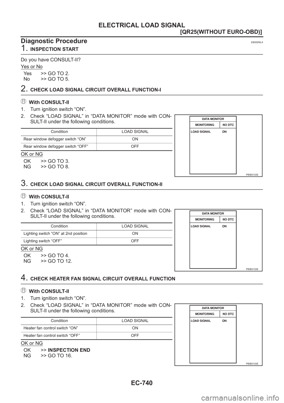
2. CHECK LOAD SIGNAL CIRCUIT OVERALL FUNCTION-I
With CONSULT-II
1. Turn ignition switch “ON”.
2. Check “LOAD SIGNAL” in “DATA MONITOR” mode with CON-
SULT-II under the following conditions.
OK or NG
OK >> GO TO 3.
NG >> GO TO 8.
3. CHECK LOAD SIGNAL CIRCUIT OVERALL FUNCTION-II
With CONSULT-II
1. Turn ignition switch “ON”.
2. Check “LOAD SIGNAL” in “DATA MONITOR” mode with CON-
SULT-II under the following conditions.
OK or NG
OK >> GO TO 4.
NG >> GO TO 12.
4. CHECK HEATER FAN SIGNAL CIRCUIT OVERALL FUNCTION
With CONSULT-II
1. Turn ignition switch “ON”.
2. Check “LOAD SIGNAL” in “DATA MONITOR” mode with CON-
SULT-II under the following conditions.
OK or NG
OK >>INSPECTION END
NG >> GO TO 16.
Condition LOAD SIGNAL
Rear window defogger switch “ON” ON
Rear window defogger switch “OFF” OFF
PBIB0103E
Condition LOAD SIGNAL
Lighting switch “ON” at 2nd position ON
Lighting switch “OFF” OFF
PBIB0103E
Condition LOAD SIGNAL
Heater fan control switch “ON” ON
Heater fan control switch “OFF” OFF
PBIB0103E
Page 1091 of 3833
ELECTRICAL LOAD SIGNAL
EC-741
[QR25(WITHOUT EURO-OBD)]
C
D
E
F
G
H
I
J
K
L
MA
EC
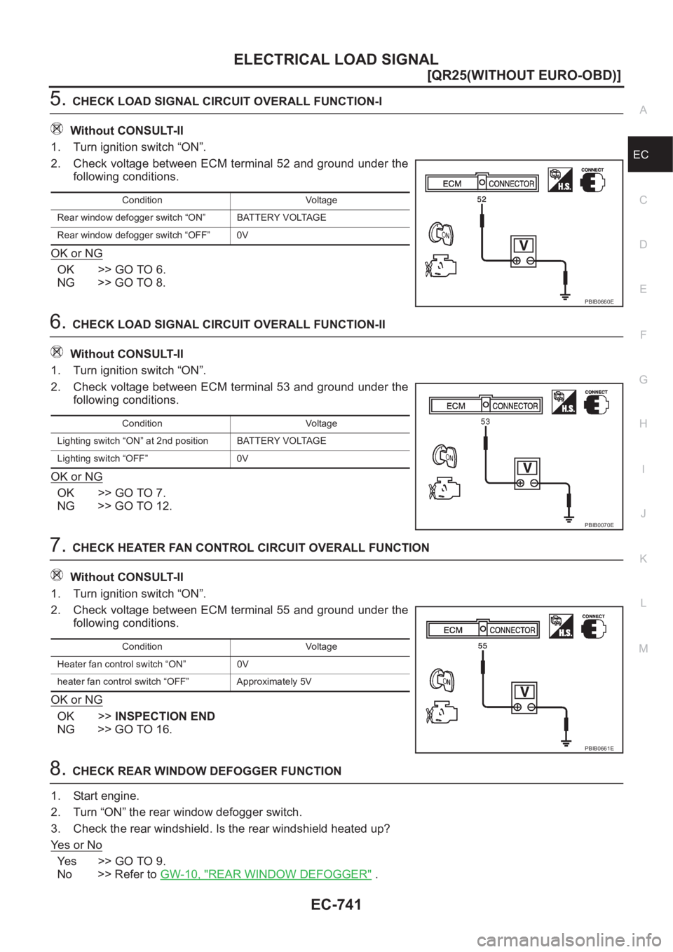
5.CHECK LOAD SIGNAL CIRCUIT OVERALL FUNCTION-I
Without CONSULT-II
1. Turn ignition switch “ON”.
2. Check voltage between ECM terminal 52 and ground under the
following conditions.
OK or NG
OK >> GO TO 6.
NG >> GO TO 8.
6.CHECK LOAD SIGNAL CIRCUIT OVERALL FUNCTION-II
Without CONSULT-II
1. Turn ignition switch “ON”.
2. Check voltage between ECM terminal 53 and ground under the
following conditions.
OK or NG
OK >> GO TO 7.
NG >> GO TO 12.
7.CHECK HEATER FAN CONTROL CIRCUIT OVERALL FUNCTION
Without CONSULT-II
1. Turn ignition switch “ON”.
2. Check voltage between ECM terminal 55 and ground under the
following conditions.
OK or NG
OK >>INSPECTION END
NG >> GO TO 16.
8.CHECK REAR WINDOW DEFOGGER FUNCTION
1. Start engine.
2. Turn “ON” the rear window defogger switch.
3. Check the rear windshield. Is the rear windshield heated up?
Ye s o r N o
Ye s > > G O T O 9 .
No >> Refer to GW-10, "
REAR WINDOW DEFOGGER" .
Condition Voltage
Rear window defogger switch “ON” BATTERY VOLTAGE
Rear window defogger switch “OFF” 0V
PBIB0660E
Condition Voltage
Lighting switch “ON” at 2nd position BATTERY VOLTAGE
Lighting switch “OFF” 0V
PBIB0070E
Condition Voltage
Heater fan control switch “ON” 0V
heater fan control switch “OFF” Approximately 5V
PBIB0661E
Page 1092 of 3833
EC-742
[QR25(WITHOUT EURO-OBD)]
ELECTRICAL LOAD SIGNAL
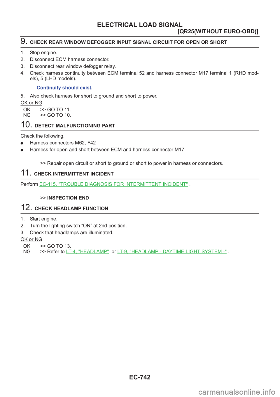
9. CHECK REAR WINDOW DEFOGGER INPUT SIGNAL CIRCUIT FOR OPEN OR SHORT
1. Stop engine.
2. Disconnect ECM harness connector.
3. Disconnect rear window defogger relay.
4. Check harness continuity between ECM terminal 52 and harness connector M17 terminal 1 (RHD mod-
els), 5 (LHD models).
5. Also check harness for short to ground and short to power.
OK or NG
OK >> GO TO 11.
NG >> GO TO 10.
10. DETECT MALFUNCTIONING PART
Check the following.
●Harness connectors M62, F42
●Harness for open and short between ECM and harness connector M17
>> Repair open circuit or short to ground or short to power in harness or connectors.
11 . CHECK INTERMITTENT INCIDENT
Perform EC-115, "
TROUBLE DIAGNOSIS FOR INTERMITTENT INCIDENT" .
>>INSPECTION END
12. CHECK HEADLAMP FUNCTION
1. Start engine.
2. Turn the lighting switch “ON” at 2nd position.
3. Check that headlamps are illuminated.
OK or NG
OK >> GO TO 13.
NG >> Refer to LT-4, "
HEADLAMP" or LT- 9 , "HEADLAMP - DAYTIME LIGHT SYSTEM -" . Continuity should exist.
Page 1101 of 3833
SERVICE DATA AND SPECIFICATIONS (SDS)
EC-751
[QR25(WITHOUT EURO-OBD)]
C
D
E
F
G
H
I
J
K
L
MA
EC
SERVICE DATA AND SPECIFICATIONS (SDS)PFP:00030
Fuel PressureEBS00NLG
Idle Speed and Ignition TimingEBS00NLH
*1: Under the following conditions:
●Air conditioner switch: OFF
●Electric load: OFF (Lights, heater fan & rear window defogger)
●Steering wheel: Kept in straight-ahead position
*2: It refrigerant pressure is low, the idle speed may not be increased.
Calculated Load ValueEBS00NLI
Mass Air Flow SensorEBS00NLJ
*: Engine is warmed up to normal operating temperature and running under no-load.
Intake Air Temperature SensorEBS00NLK
Engine Coolant Temperature SensorEBS00NLL
Heated Oxygen Sensor 1 HeaterEBS00NLM
Heated Oxygen sensor 2 HeaterEBS00NLN
Crankshaft Position Sensor (POS)EBS00NLO
Refer to EC-556, "Component Inspection" .
Fuel pressure at idle kPa (bar, kg/cm2 , psi)Approximately 350 (3.5, 3.57, 51)
Target idle speed
No-load*1 (in “P” or N” position)A/T: 700±50 rpm
M/T: 700±50 rpm
Air conditioner: ONIn “P” or N” position
A/T: 700 rpm or more*
2
M/T: 750 rpm or more*2
Ignition timingIn “P” or N” position AT: 15°±5° BTDC
MT: 15°±5° BTDC
Calculated load value% (Using CONSULT-II or GST)
At idle10 - 35
At 2,500 rpm10 - 35
Supply voltageBattery voltage (11 - 14V)
Output voltage at idle1.1 - 1.5*V
Mass air flow (Using CONSULT-II or GST)1.4 - 4.0 g·m/sec at idle*
4.0 - 10.0 g·m/sec at 2,500 rpm*
Temperature °C (°F) Resistance kΩ
25 (77)1.9 - 2.1
80 (176)0.31 - 0.37
Temperature °C (°F) Resistance kΩ
20 (68) 2.1 - 2.9
50 (122) 0.68 - 1.00
90 (194) 0.236 - 0.260
Resistance [at 25°C (77°F)] 2.3 - 4.3Ω
Resistance [at 25°C (77°F)] 2.3 - 4.3Ω
Page 1123 of 3833
BASIC SERVICE PROCEDURE
EC-773
[QR20(WITH EURO-OBD)]
C
D
E
F
G
H
I
J
K
L
MA
EC
Learning will be cancelled if any of the following conditions are missed for even a moment.
●Battery voltage: More than 12.9V (At idle)
●Engine coolant temperature: 70 - 100°C (158 - 212°F)
●PNP switch: ON
●Electric load switch: OFF
(Air conditioner, headlamp, rear window defogger)
On vehicles equipped with daytime light systems, set lighting switch to the 1st position to light
only small lamps.
●Steering wheel: Neutral (Straight-ahead position)
●Vehicle speed: Stopped
●Transmission: Warmed-up
For A/T models with CONSULT-II, drive vehicle until “FLUID TEMP SE” in “DATA MONITOR” mode of “A/
T” system indicates less than 0.9V.
For A/T models without CONSULT-II and M/T models, drive vehicle for 10 minutes.
OPERATION PROCEDURE
With CONSULT-II
1. Perform EC-772, "Accelerator Pedal Released Position Learning" .
2. Perform EC-772, "
Throttle Valve Closed Position Learning" .
3. Start engine and warm it up to normal operating temperature.
4. Check that all items listed under the topic “PREPARATION” (previously mentioned) are in good order.
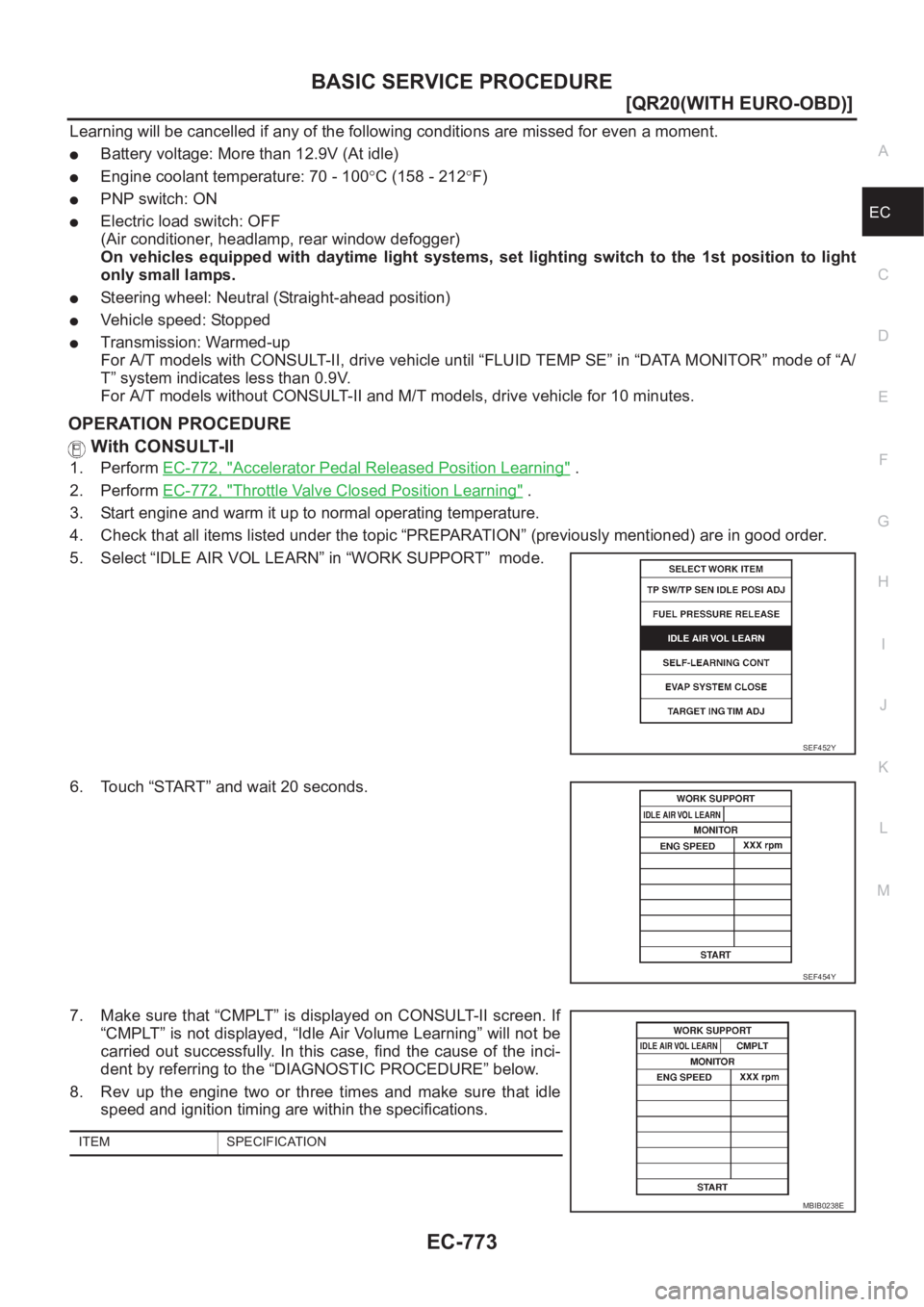
5. Select “IDLE AIR VOL LEARN” in “WORK SUPPORT” mode.
6. Touch “START” and wait 20 seconds.
7. Make sure that “CMPLT” is displayed on CONSULT-II screen. If
“CMPLT” is not displayed, “Idle Air Volume Learning” will not be
carried out successfully. In this case, find the cause of the inci-
dent by referring to the “DIAGNOSTIC PROCEDURE” below.
8. Rev up the engine two or three times and make sure that idle
speed and ignition timing are within the specifications.
SEF452Y
SEF454Y
ITEM SPECIFICATION
MBIB0238E
Page 1155 of 3833
TROUBLE DIAGNOSIS
EC-805
[QR20(WITH EURO-OBD)]
C
D
E
F
G
H
I
J
K
L
MA
EC
Basic InspectionEBS00MSU
1.INSPECTION START
1. Check service records for any recent repairs that may indicate a related incident, or a current need for
scheduled maintenance.
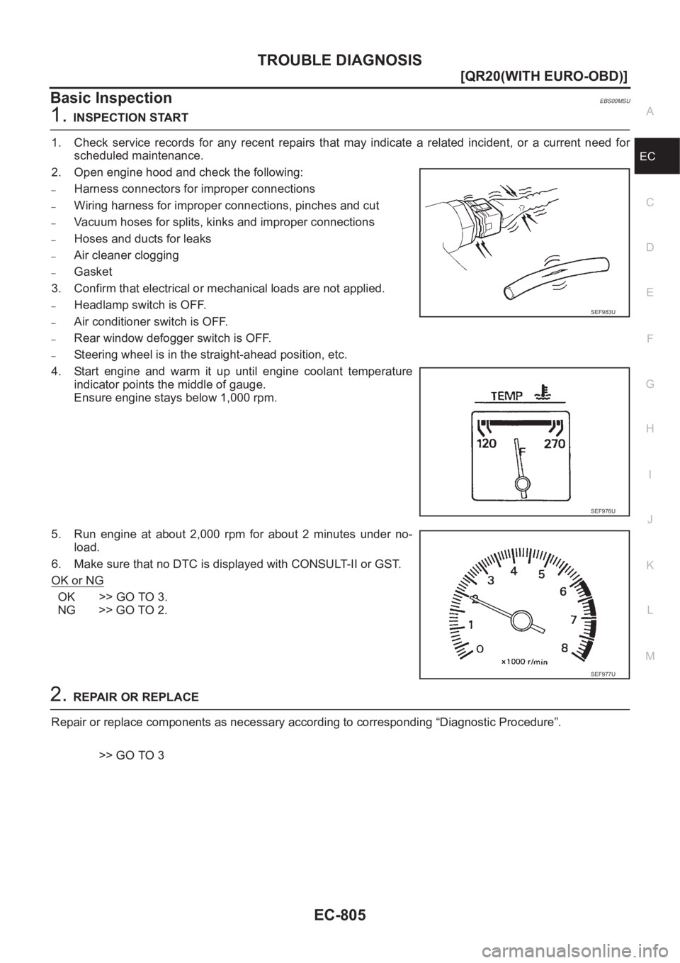
2. Open engine hood and check the following:
–Harness connectors for improper connections
–Wiring harness for improper connections, pinches and cut
–Vacuum hoses for splits, kinks and improper connections
–Hoses and ducts for leaks
–Air cleaner clogging
–Gasket
3. Confirm that electrical or mechanical loads are not applied.
–Headlamp switch is OFF.
–Air conditioner switch is OFF.
–Rear window defogger switch is OFF.
–Steering wheel is in the straight-ahead position, etc.
4. Start engine and warm it up until engine coolant temperature
indicator points the middle of gauge.
Ensure engine stays below 1,000 rpm.
5. Run engine at about 2,000 rpm for about 2 minutes under no-
load.
6. Make sure that no DTC is displayed with CONSULT-II or GST.
OK or NG
OK >> GO TO 3.
NG >> GO TO 2.
2.REPAIR OR REPLACE
Repair or replace components as necessary according to corresponding “Diagnostic Procedure”.
>> GO TO 3
SEF983U
SEF976U
SEF977U
Page 1172 of 3833
EC-822
[QR20(WITH EURO-OBD)]
TROUBLE DIAGNOSIS
42 B/R Ignition switch[Ignition switch “OFF”]0V
[Ignition switch “ON”]BATTERY VOLTAGE
(11 - 14V)
43 G/OR PNP switch[Ignition switch “ON”]
●Gear position is “P” or “N”.Approximately 0V
[Ignition switch “ON”]
●Except the above gear positionA/T model
BATTERY VOLTAGE
(11 - 14V)
M/T model
Approximately 5V
50 LG Data link connector[Ignition switch “ON”]
●CONSULT-II or GST is disconnected.Approximately 5V
52 R/WElectrical load signal
(Rear window defog-
ger signal)[Ignition switch “ON”]
●Rear window defogger switch is “ON”BATTERY VOLTAGE
(11 - 14V)
[Ignition switch “ON”]
●Rear window defogger switch is “OFF”Approximately 0V
53 R/YElectrical load signal
(Headlamp signal)[Ignition switch “ON”]
●Lighting switch is “2ND” positionBATTERY VOLTAGE
(11 - 14V)
[Ignition switch “ON”]
●Lighting switch is “OFF”Approximately 0V
55 LG/BHeater fan switch sig-
nal[Ignition switch “ON”]
●Heater fan control switch is “ON”Approximately 0V
[Ignition switch “ON”]
●Heater fan control switch is “OFF”Approximately 5V
58 B Sensors' ground[Engine is running]
●Warm-up condition
●Idle speedApproximately 0V
59
60
106
108B
B
B/Y
B/YECM ground[Engine is running]
●Idle speedEngine ground
63 L/WCamshaft position
sensor (PHASE)[Engine is running]
●Warm-up condition
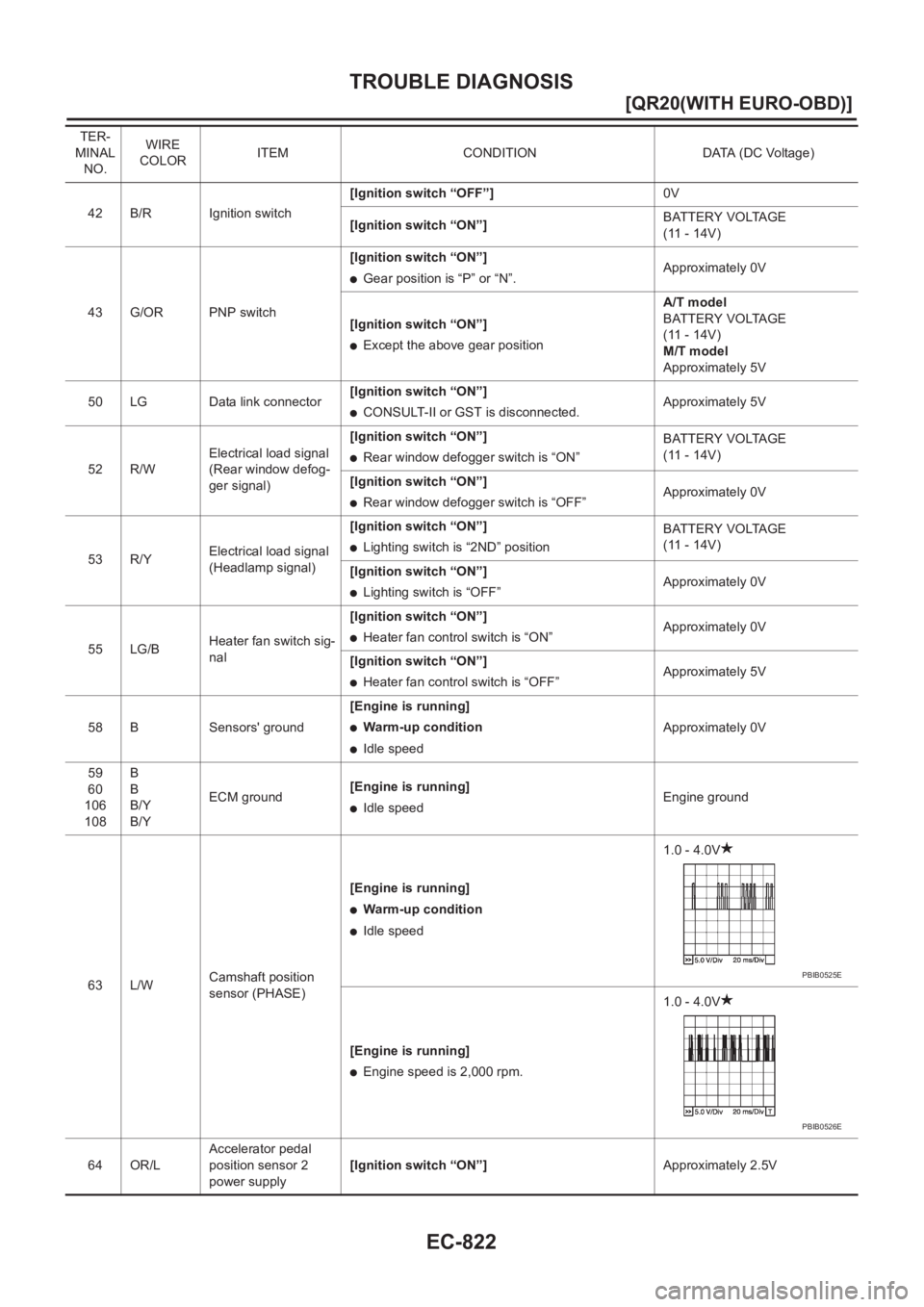
●Idle speed1.0 - 4.0V
[Engine is running]
●Engine speed is 2,000 rpm.1.0 - 4.0V
64 OR/LAccelerator pedal
position sensor 2
power supply[Ignition switch “ON”]Approximately 2.5V TER-
MINAL
NO.WIRE
COLORITEM CONDITION DATA (DC Voltage)
PBIB0525E
PBIB0526E
Page 1181 of 3833
TROUBLE DIAGNOSIS
EC-831
[QR20(WITH EURO-OBD)]
C
D
E
F
G
H
I
J
K
L
MA
EC
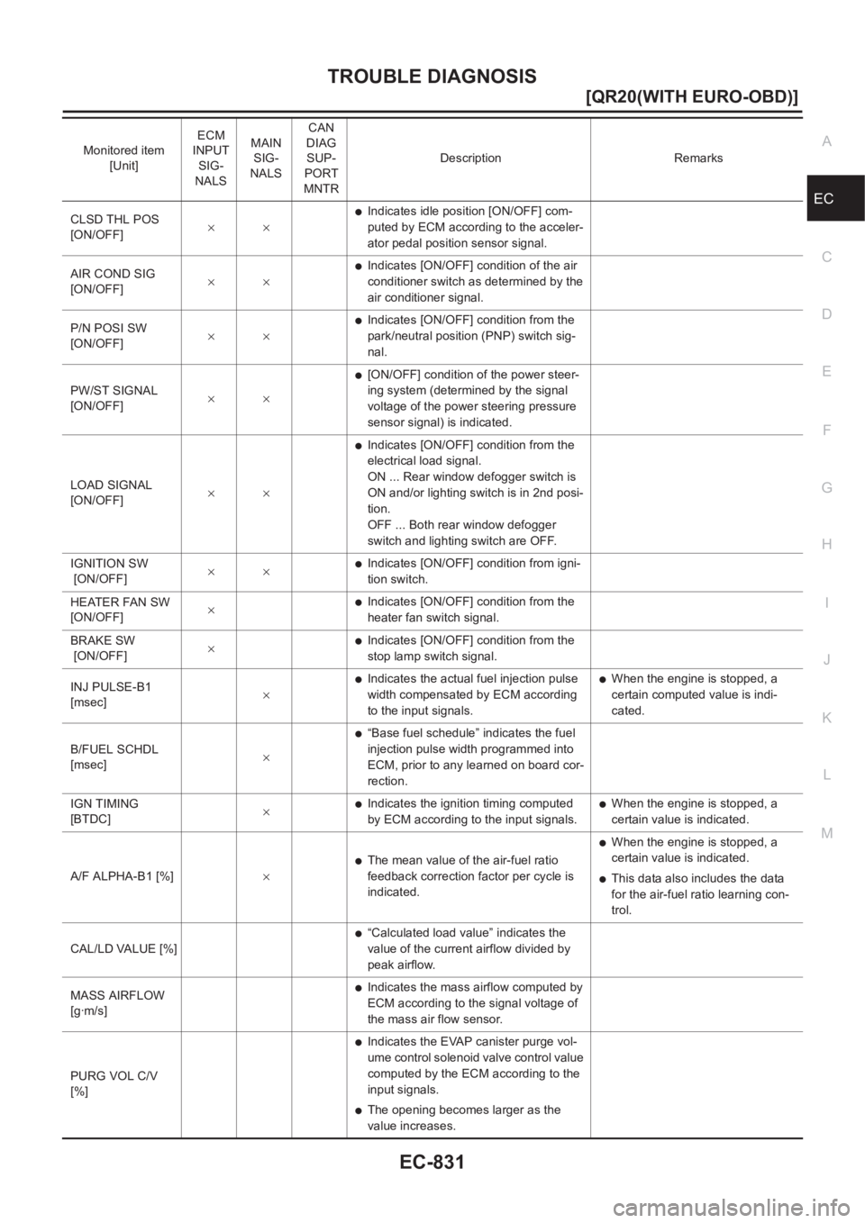
CLSD THL POS
[ON/OFF]××●Indicates idle position [ON/OFF] com-
puted by ECM according to the acceler-
ator pedal position sensor signal.
AIR COND SIG
[ON/OFF]××
●Indicates [ON/OFF] condition of the air
conditioner switch as determined by the
air conditioner signal.
P/N POSI SW
[ON/OFF]××
●Indicates [ON/OFF] condition from the
park/neutral position (PNP) switch sig-
nal.
PW/ST SIGNAL
[ON/OFF]××
●[ON/OFF] condition of the power steer-
ing system (determined by the signal
voltage of the power steering pressure
sensor signal) is indicated.
LOAD SIGNAL
[ON/OFF]××
●Indicates [ON/OFF] condition from the
electrical load signal.
ON ... Rear window defogger switch is
ON and/or lighting switch is in 2nd posi-
tion.
OFF ... Both rear window defogger
switch and lighting switch are OFF.
IGNITION SW
[ON/OFF]××
●Indicates [ON/OFF] condition from igni-
tion switch.
HEATER FAN SW
[ON/OFF]×
●Indicates [ON/OFF] condition from the
heater fan switch signal.
BRAKE SW
[ON/OFF]×
●Indicates [ON/OFF] condition from the
stop lamp switch signal.
INJ PULSE-B1
[msec]×
●Indicates the actual fuel injection pulse
width compensated by ECM according
to the input signals.●When the engine is stopped, a
certain computed value is indi-
cated.
B/FUEL SCHDL
[msec]×
●“Base fuel schedule” indicates the fuel
injection pulse width programmed into
ECM, prior to any learned on board cor-
rection.
IGN TIMING
[BTDC]×
●Indicates the ignition timing computed
by ECM according to the input signals.●When the engine is stopped, a
certain value is indicated.
A/F ALPHA-B1 [%]×
●The mean value of the air-fuel ratio
feedback correction factor per cycle is
indicated.
●When the engine is stopped, a
certain value is indicated.
●This data also includes the data
for the air-fuel ratio learning con-
trol.
CAL/LD VALUE [%]
●“Calculated load value” indicates the
value of the current airflow divided by
peak airflow.
MASS AIRFLOW
[g·m/s]
●Indicates the mass airflow computed by
ECM according to the signal voltage of
the mass air flow sensor.
PURG VOL C/V
[%]
●Indicates the EVAP canister purge vol-
ume control solenoid valve control value
computed by the ECM according to the
input signals.
●The opening becomes larger as the
value increases. Monitored item
[Unit]ECM
INPUT
SIG-
NALSMAIN
SIG-
NALSCAN
DIAG
SUP-
PORT
MNTRDescription Remarks
Page 1189 of 3833
TROUBLE DIAGNOSIS
EC-839
[QR20(WITH EURO-OBD)]
C
D
E
F
G
H
I
J
K
L
MA
EC
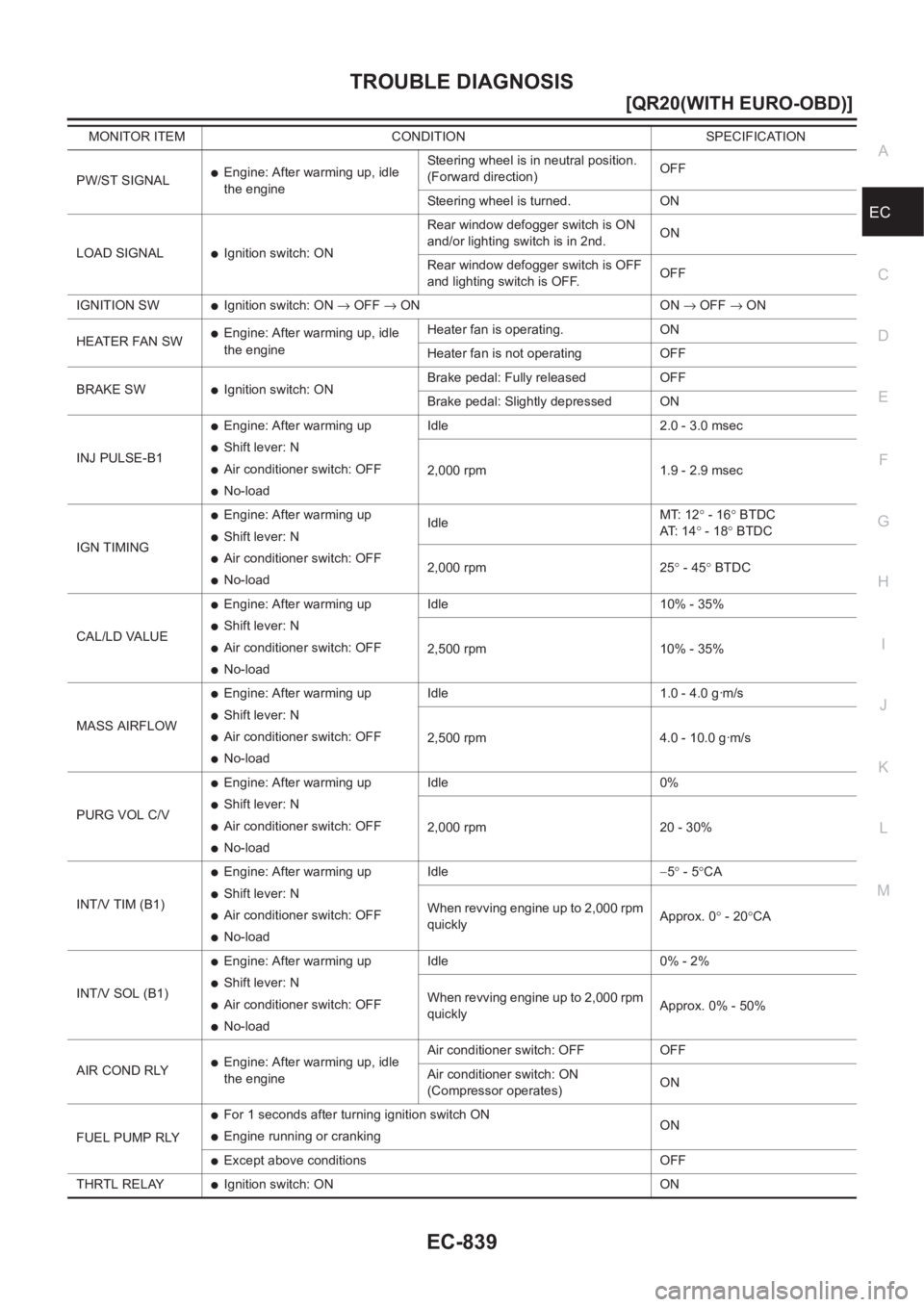
PW/ST SIGNAL●Engine: After warming up, idle
the engineSteering wheel is in neutral position.
(Forward direction)OFF
Steering wheel is turned. ON
LOAD SIGNAL
●Ignition switch: ONRear window defogger switch is ON
and/or lighting switch is in 2nd.ON
Rear window defogger switch is OFF
and lighting switch is OFF.OFF
IGNITION SW
●Ignition switch: ON → OFF → ON ON → OFF → ON
HEATER FAN SW
●Engine: After warming up, idle
the engineHeater fan is operating. ON
Heater fan is not operating OFF
BRAKE SW
●Ignition switch: ONBrake pedal: Fully released OFF
Brake pedal: Slightly depressed ON
INJ PULSE-B1
●Engine: After warming up
●Shift lever: N
●Air conditioner switch: OFF
●No-loadIdle 2.0 - 3.0 msec
2,000 rpm 1.9 - 2.9 msec
IGN TIMING
●Engine: After warming up
●Shift lever: N
●Air conditioner switch: OFF
●No-loadIdleMT: 12° - 16° BTDC
AT: 1 4° - 18° BTDC
2,000 rpm 25° - 45° BTDC
CAL/LD VALUE
●Engine: After warming up
●Shift lever: N
●Air conditioner switch: OFF
●No-loadIdle 10% - 35%
2,500 rpm 10% - 35%
MASS AIRFLOW
●Engine: After warming up
●Shift lever: N
●Air conditioner switch: OFF
●No-loadIdle 1.0 - 4.0 g·m/s
2,500 rpm 4.0 - 10.0 g·m/s
PURG VOL C/V
●Engine: After warming up
●Shift lever: N
●Air conditioner switch: OFF
●No-loadIdle 0%
2,000 rpm 20 - 30%
INT/V TIM (B1)
●Engine: After warming up
●Shift lever: N
●Air conditioner switch: OFF
●No-loadIdle−5° - 5°CA
When revving engine up to 2,000 rpm
quicklyApprox. 0° - 20°CA
INT/V SOL (B1)
●Engine: After warming up
●Shift lever: N
●Air conditioner switch: OFF
●No-loadIdle 0% - 2%
When revving engine up to 2,000 rpm
quicklyApprox. 0% - 50%
AIR COND RLY
●Engine: After warming up, idle
the engineAir conditioner switch: OFF OFF
Air conditioner switch: ON
(Compressor operates)ON
FUEL PUMP RLY
●For 1 seconds after turning ignition switch ON
●Engine running or crankingON
●Except above conditions OFF
THRTL RELAY
●Ignition switch: ON ON MONITOR ITEM CONDITION SPECIFICATION
Page 1193 of 3833
TROUBLE DIAGNOSIS - SPECIFICATION VALUE
EC-843
[QR20(WITH EURO-OBD)]
C
D
E
F
G
H
I
J
K
L
MA
EC
TROUBLE DIAGNOSIS - SPECIFICATION VALUEPFP:00031
DescriptionEBS00MT4
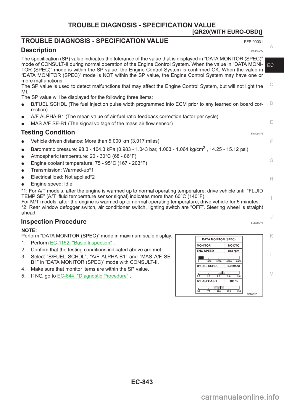
The specification (SP) value indicates the tolerance of the value that is displayed in “DATA MONITOR (SPEC)”
mode of CONSULT-II during normal operation of the Engine Control System. When the value in “DATA MONI-
TOR (SPEC)” mode is within the SP value, the Engine Control System is confirmed OK. When the value in
“DATA MONITOR (SPEC)” mode is NOT within the SP value, the Engine Control System may have one or
more malfunctions.
The SP value is used to detect malfunctions that may affect the Engine Control System, but will not light the
MI.
The SP value will be displayed for the following three items:
●B/FUEL SCHDL (The fuel injection pulse width programmed into ECM prior to any learned on board cor-
rection)
●A/F ALPHA-B1 (The mean value of air-fuel ratio feedback correction factor per cycle)
●MAS A/F SE-B1 (The signal voltage of the mass air flow sensor)
Testing ConditionEBS00MT5
●Vehicle driven distance: More than 5,000 km (3,017 miles)
●Barometric pressure: 98.3 - 104.3 kPa (0.983 - 1.043 bar, 1.003 - 1.064 kg/cm2 , 14.25 - 15.12 psi)
●Atmospheric temperature: 20 - 30°C (68 - 86°F)
●Engine coolant temperature: 75 - 95°C (167 - 203°F)
●Transmission: Warmed-up*1
●Electrical load: Not applied*2
●Engine speed: Idle
*1: For A/T models, after the engine is warmed up to normal operating temperature, drive vehicle until “FLUID
TEMP SE” (A/T fluid temperature sensor signal) indicates more than 60°C (140°F).
For M/T models, after the engine is warmed up to normal operating temperature, drive vehicle for 5 minutes.
*2: Rear window defogger switch, air conditioner switch, lighting switch are “OFF”. Steering wheel is straight
ahead.
Inspection ProcedureEBS00MT6
NOTE:
Perform “DATA MONITOR (SPEC)” mode in maximum scale display.
1. Perform EC-1152, "
Basic Inspection" .
2. Confirm that the testing conditions indicated above are met.
3. Select “B/FUEL SCHDL”, “A/F ALPHA-B1” and “MAS A/F SE-
B1” in “DATA MONITOR (SPEC)” mode with CONSULT-II.
4. Make sure that monitor items are within the SP value.
5. If NG, go to EC-844, "
Diagnostic Procedure" .
SEF601Z