NISSAN X-TRAIL 2001 Service Repair Manual
Manufacturer: NISSAN, Model Year: 2001, Model line: X-TRAIL, Model: NISSAN X-TRAIL 2001Pages: 3833, PDF Size: 39.49 MB
Page 3331 of 3833
TROUBLE DIAGNOSIS
ATC-55
C
D
E
F
G
H
I
K
L
MA
B
AT C
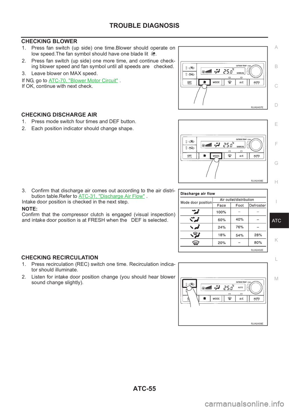
CHECKING BLOWER
1. Press fan switch (up side) one time.Blower should operate on
low speed.The fan symbol should have one blade lit .
2. Press fan switch (up side) one more time, and continue check-
ing blower speed and fan symbol until all speeds are checked.
3. Leave blower on MAX speed.
If NG, go to ATC-70, "
Blower Motor Circuit" .
If OK, continue with next check.
CHECKING DISCHARGE AIR
1. Press mode switch four times and DEF button.
2. Each position indicator should change shape.
3. Confirm that discharge air comes out according to the air distri-
bution table.Refer to AT C - 3 1 , "
Discharge Air Flow" .
Intake door position is checked in the next step.
NOTE:
Confirm that the compressor clutch is engaged (visual inspection)
and intake door position is at FRESH when the DEF is selected.
CHECKING RECIRCULATION
1. Press recirculation (REC) switch one time. Recirculation indica-
tor should illuminate.
2. Listen for intake door position change (you should hear blower
sound change slightly).
RJIA0497E
RJIA0498E
RJIA0492E
RJIA0499E
Page 3332 of 3833
ATC-56
TROUBLE DIAGNOSIS
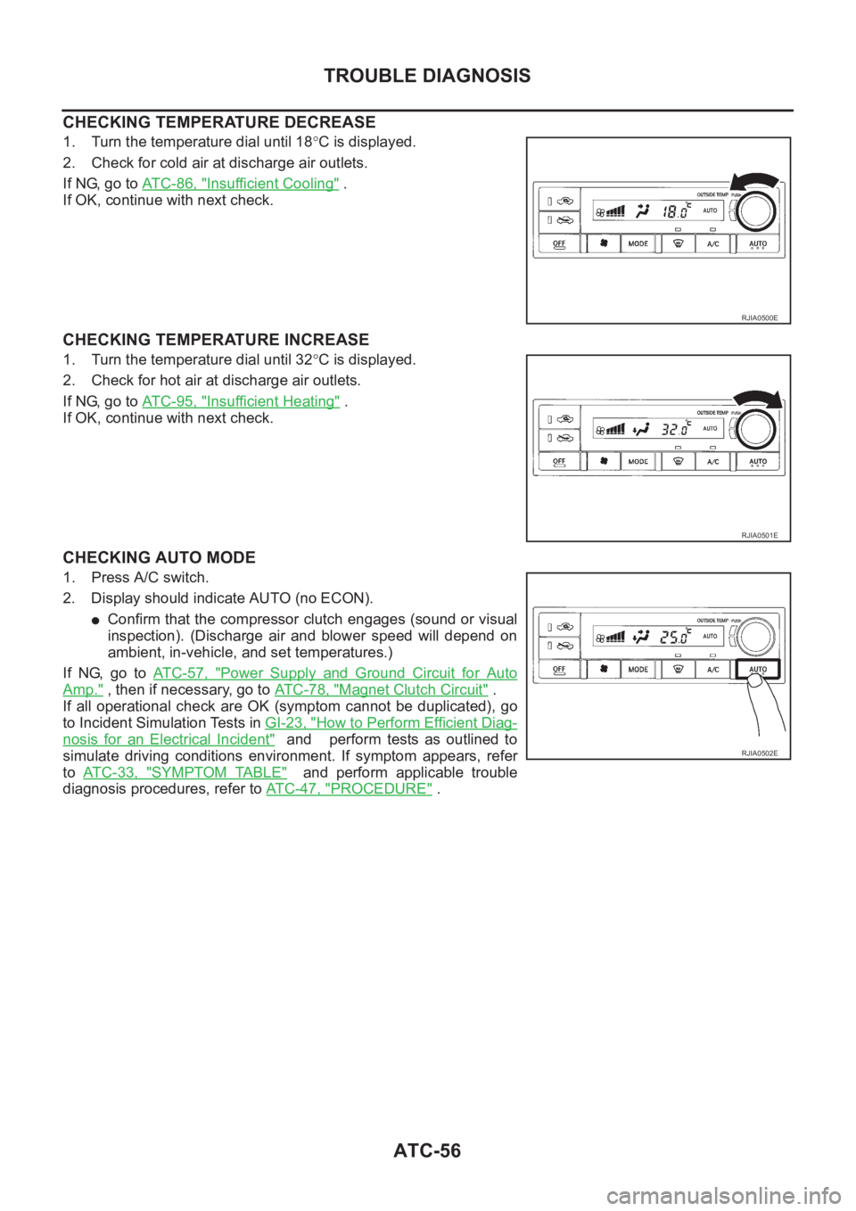
CHECKING TEMPERATURE DECREASE
1. Turn the temperature dial until 18°C is displayed.
2. Check for cold air at discharge air outlets.
If NG, go to AT C - 8 6 , "
Insufficient Cooling" .
If OK, continue with next check.
CHECKING TEMPERATURE INCREASE
1. Turn the temperature dial until 32°C is displayed.
2. Check for hot air at discharge air outlets.
If NG, go to AT C - 9 5 , "
Insufficient Heating" .
If OK, continue with next check.
CHECKING AUTO MODE
1. Press A/C switch.
2. Display should indicate AUTO (no ECON).
●Confirm that the compressor clutch engages (sound or visual
inspection). (Discharge air and blower speed will depend on
ambient, in-vehicle, and set temperatures.)
If NG, go to AT C - 5 7 , "
Power Supply and Ground Circuit for Auto
Amp." , then if necessary, go to AT C - 7 8 , "Magnet Clutch Circuit" .
If all operational check are OK (symptom cannot be duplicated), go
to Incident Simulation Tests in GI-23, "
How to Perform Efficient Diag-
nosis for an Electrical Incident" and perform tests as outlined to
simulate driving conditions environment. If symptom appears, refer
to AT C - 3 3 , "
SYMPTOM TABLE" and perform applicable trouble
diagnosis procedures, refer to ATC-47, "
PROCEDURE" .
RJIA0500E
RJIA0501E
RJIA0502E
Page 3333 of 3833
TROUBLE DIAGNOSIS
ATC-57
C
D
E
F
G
H
I
K
L
MA
B
AT C
Power Supply and Ground Circuit for Auto Amp.EJS001GZ
SYMPTOM: A/C system does not come on.
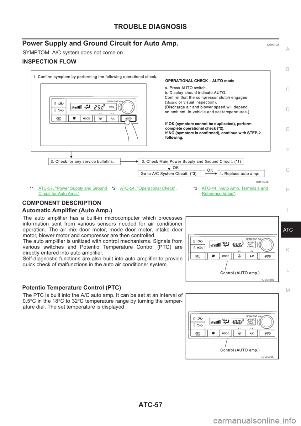
INSPECTION FLOW
COMPONENT DESCRIPTION
Automatic Amplifier (Auto Amp.)
The auto amplifier has a built-in microcomputer which processes
information sent from various sensors needed for air conditioner
operation. The air mix door motor, mode door motor, intake door
motor, blower motor and compressor are then controlled.
The auto amplifier is unitized with control mechanisms. Signals from
various switches and Potentio Temperature Control (PTC) are
directly entered into auto amplifier.
Self-diagnostic functions are also built into auto amplifier to provide
quick check of malfunctions in the auto air conditioner system.
Potentio Temperature Control (PTC)
The PTC is built into the A/C auto amp. It can be set at an interval of
0.5°C in the 18°C to 32°C temperature range by turning the temper-
ature dial. The set temperature is displayed.
*1AT C - 5 7 , "Power Supply and Ground
Circuit for Auto Amp.".*2AT C - 5 4 , "
Operational Check".*3AT C - 4 4 , "Auto Amp. Terminals and
Reference Value".
RJIA1945E
RJIA0488E
RJIA0488E
Page 3334 of 3833
ATC-58
TROUBLE DIAGNOSIS
DIAGNOSTIC PROCEDURE
SYMPTOM: A/C system does not come on.
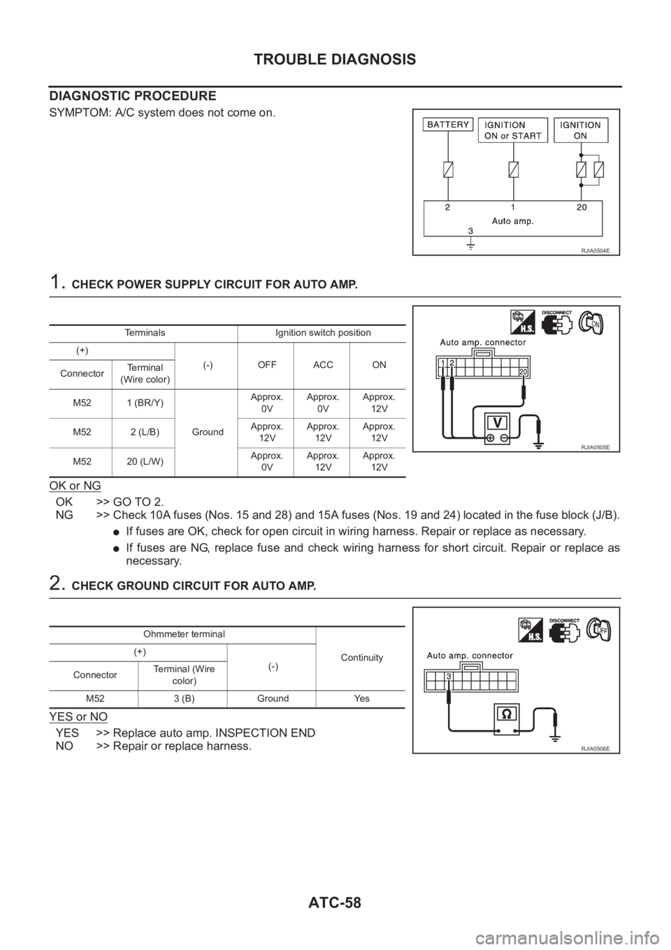
1. CHECK POWER SUPPLY CIRCUIT FOR AUTO AMP.
OK or NG
OK >> GO TO 2.
NG >> Check 10A fuses (Nos. 15 and 28) and 15A fuses (Nos. 19 and 24) located in the fuse block (J/B).
●If fuses are OK, check for open circuit in wiring harness. Repair or replace as necessary.
●If fuses are NG, replace fuse and check wiring harness for short circuit. Repair or replace as
necessary.
2. CHECK GROUND CIRCUIT FOR AUTO AMP.
YES or NO
YES >> Replace auto amp. INSPECTION END
NO >> Repair or replace harness.
RJIA0504E
Terminals Ignition switch position
(+)
(-) OFF ACC ON
ConnectorTerminal
(Wire color)
M52 1 (BR/Y)
GroundApprox.
0VApprox.
0VApprox.
12V
M52 2 (L/B)Approx.
12VApprox.
12VApprox.
12V
M52 20 (L/W)Approx.
0VApprox.
12VApprox.
12V
RJIA0505E
Ohmmeter terminal
Continuity (+)
(-)
ConnectorTe r m i n a l ( W i r e
color)
M52 3 (B) Ground Yes
RJIA0506E
Page 3335 of 3833
TROUBLE DIAGNOSIS
ATC-59
C
D
E
F
G
H
I
K
L
MA
B
AT C
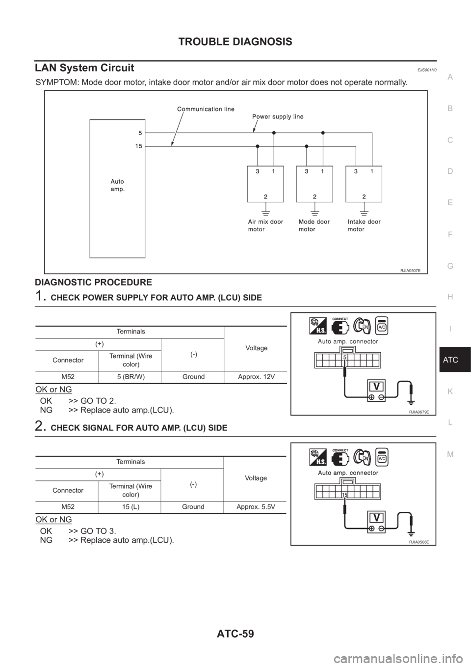
LAN System CircuitEJS001H0
SYMPTOM: Mode door motor, intake door motor and/or air mix door motor does not operate normally.
DIAGNOSTIC PROCEDURE
1.CHECK POWER SUPPLY FOR AUTO AMP. (LCU) SIDE
OK or NG
OK >> GO TO 2.
NG >> Replace auto amp.(LCU).
2.CHECK SIGNAL FOR AUTO AMP. (LCU) SIDE
OK or NG
OK >> GO TO 3.
NG >> Replace auto amp.(LCU).
RJIA0507E
Terminals
Vo lta g e (+)
(-)
ConnectorTerminal (Wire
color)
M52 5 (BR/W) Ground Approx. 12V
RJIA0679E
Te r m i n a l s
Voltage (+)
(-)
ConnectorTe r m i n a l ( W i r e
color)
M52 15 (L) Ground Approx. 5.5V
RJIA0508E
Page 3336 of 3833
ATC-60
TROUBLE DIAGNOSIS
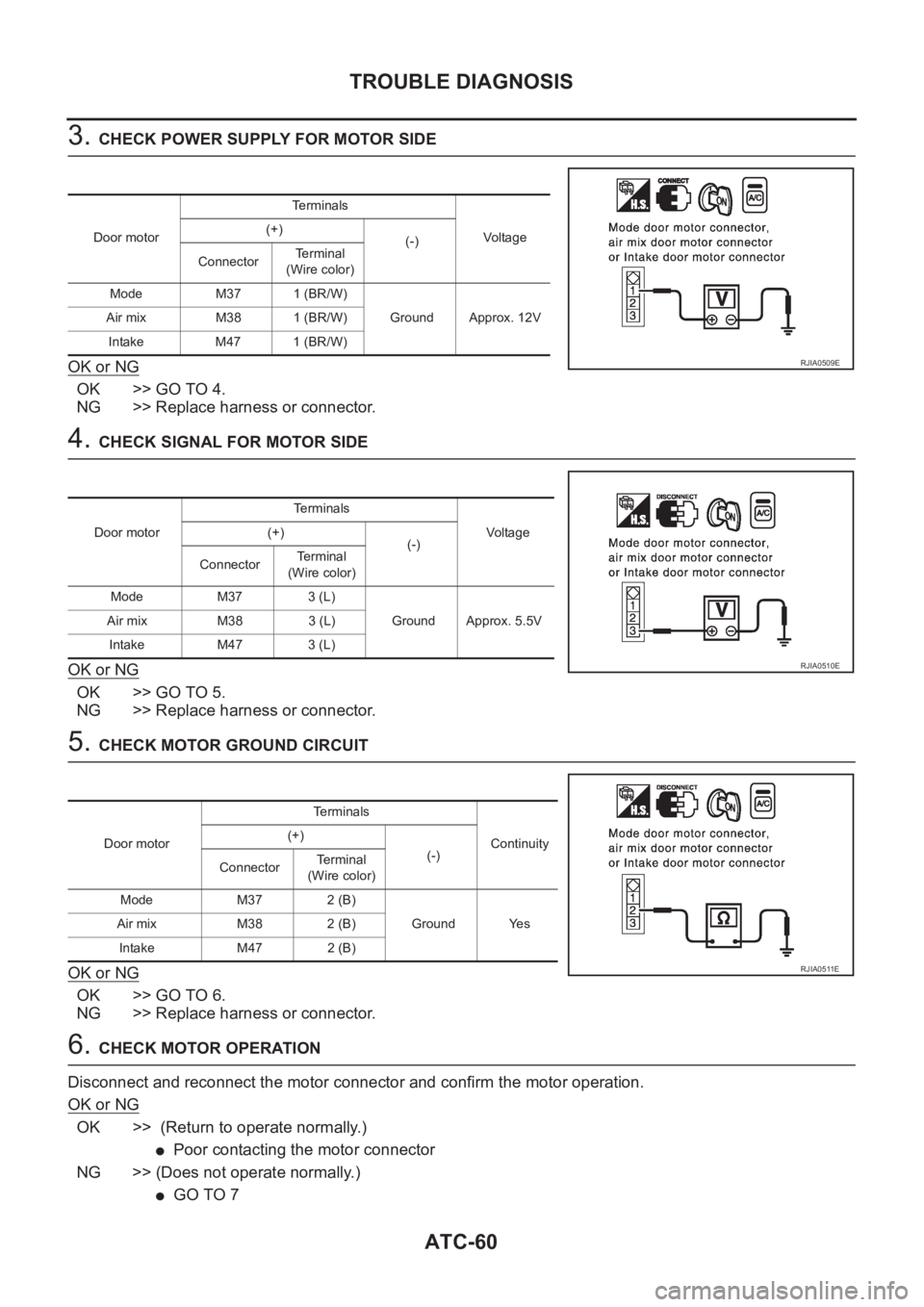
3. CHECK POWER SUPPLY FOR MOTOR SIDE
OK or NG
OK >> GO TO 4.
NG >> Replace harness or connector.
4. CHECK SIGNAL FOR MOTOR SIDE
OK or NG
OK >> GO TO 5.
NG >> Replace harness or connector.
5. CHECK MOTOR GROUND CIRCUIT
OK or NG
OK >> GO TO 6.
NG >> Replace harness or connector.
6. CHECK MOTOR OPERATION
Disconnect and reconnect the motor connector and confirm the motor operation.
OK or NG
OK >> (Return to operate normally.)
●Poor contacting the motor connector
NG >> (Does not operate normally.)
●GO TO 7
Door motorTerminals
Vo l ta g e (+)
(-)
ConnectorTerminal
(Wire color)
Mode M37 1 (BR/W)
Ground Approx. 12V Air mix M38 1 (BR/W)
Intake M47 1 (BR/W)
RJIA0509E
Door motorTerminals
Vo l ta g e (+)
(-)
ConnectorTerminal
(Wire color)
Mode M37 3 (L)
Ground Approx. 5.5V Air mix M38 3 (L)
Intake M47 3 (L)
RJIA0510E
Door motorTerminals
Continuity (+)
(-)
ConnectorTerminal
(Wire color)
Mode M37 2 (B)
Ground Yes Air mix M38 2 (B)
Intake M47 2 (B)
RJIA0511E
Page 3337 of 3833
TROUBLE DIAGNOSIS
ATC-61
C
D
E
F
G
H
I
K
L
MA
B
AT C
7.CHECK MODE DOOR MOTOR OPERATION
1. Disconnect mode door motor and air mix door motor connector.
2. Reconnect mode door motor connector and confirm the mode door motor operation.
OK or NG
OK >> (Mode door motor operates normally.)
●GO TO 8
NG >> (Mode door motor does not operate normally.)
●Replace the mode door motor.
8.CHECK AIR MIX DOOR MOTOR OPERATION
1. Disconnect mode door motor connector.
2. Reconnect air mix door motor connector and confirm the air mix door motor operation.
OK or NG
OK >> (Air mix door motor operates normally.)
●GO TO 9
NG >> (Air mix door motor does not operate normally.)
●Replace the air mix door motor.
9.CHECK INTAKE DOOR MOTOR OPERATION
1. Disconnect air mix door motor connector.
2. Reconnect intake door motor connector and confirm the intake door motor operation.
OK or NG
OK >> (Intake door motor operates normally.)
●Replace auto amp.
NG >> (Intake door motor does not operate normally.)
●Replace intake door motor.
Page 3338 of 3833
ATC-62
TROUBLE DIAGNOSIS
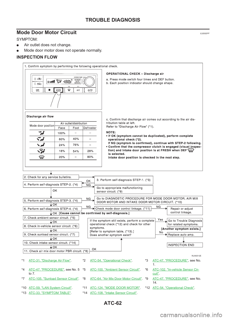
Mode Door Motor Circuit
EJS002FP
SYMPTOM:
●Air outlet does not change.
●Mode door motor does not operate normally.
INSPECTION FLOW
*1ATC-31, "Discharge Air Flow".*2AT C - 5 4 , "Operational Check".*3ATC-47, "PROCEDURE", see No.
1.
*4ATC-47, "
PROCEDURE", see No. 5
to 7.*5ATC-100, "Ambient Sensor Circuit".*6ATC-102, "In-vehicle Sensor Cir-
cuit".
*7ATC-105, "
Sunload Sensor Circuit".*8AT C - 6 4 , "Air Mix Door Motor Circuit".*9ATC-47, "PROCEDURE", see No.
14.
*10ATC-59, "
LAN System Circuit".*11ATC-124, "MODE DOOR MOTOR".*12ATC-54, "Operational Check".
*13ATC-33, "
SYMPTOM TABLE".*14ATC-108, "Intake Sensor Circuit".
RJIA0512E
Page 3339 of 3833
TROUBLE DIAGNOSIS
ATC-63
C
D
E
F
G
H
I
K
L
MA
B
AT C
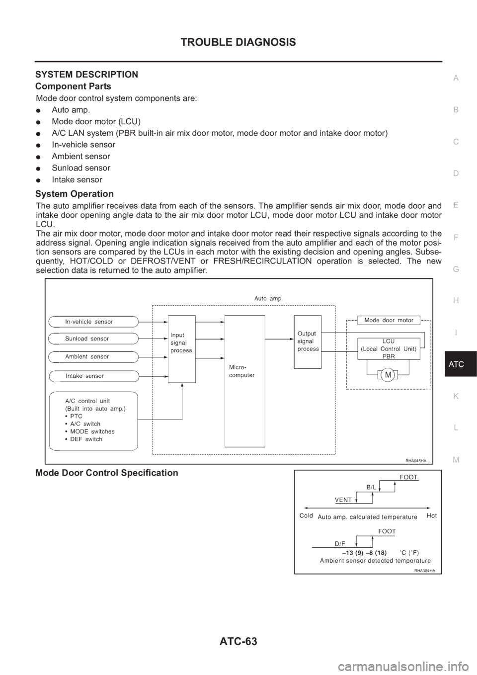
SYSTEM DESCRIPTION
Component Parts
Mode door control system components are:
●Auto amp.
●Mode door motor (LCU)
●A/C LAN system (PBR built-in air mix door motor, mode door motor and intake door motor)
●In-vehicle sensor
●Ambient sensor
●Sunload sensor
●Intake sensor
System Operation
The auto amplifier receives data from each of the sensors. The amplifier sends air mix door, mode door and
intake door opening angle data to the air mix door motor LCU, mode door motor LCU and intake door motor
LCU.
The air mix door motor, mode door motor and intake door motor read their respective signals according to the
address signal. Opening angle indication signals received from the auto amplifier and each of the motor posi-
tion sensors are compared by the LCUs in each motor with the existing decision and opening angles. Subse-
quently, HOT/COLD or DEFROST/VENT or FRESH/RECIRCULATION operation is selected. The new
selection data is returned to the auto amplifier.
Mode Door Control Specification
RHA045HA
RHA384HA
Page 3340 of 3833
ATC-64
TROUBLE DIAGNOSIS
COMPONENT DESCRIPTION
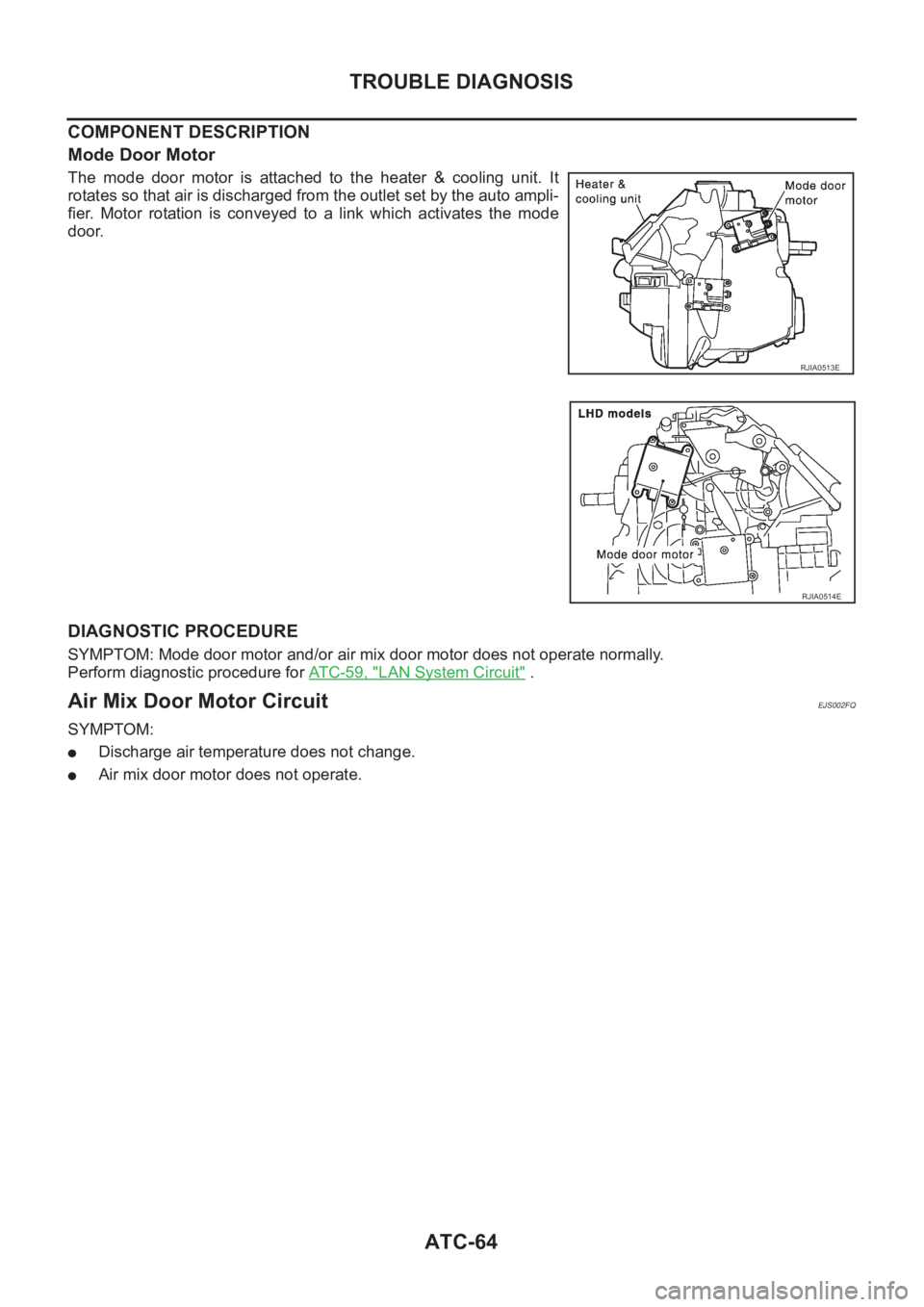
Mode Door Motor
The mode door motor is attached to the heater & cooling unit. It
rotates so that air is discharged from the outlet set by the auto ampli-
fier. Motor rotation is conveyed to a link which activates the mode
door.
DIAGNOSTIC PROCEDURE
SYMPTOM: Mode door motor and/or air mix door motor does not operate normally.
Perform diagnostic procedure for ATC-59, "
LAN System Circuit" .
Air Mix Door Motor CircuitEJS002FQ
SYMPTOM:
●Discharge air temperature does not change.
●Air mix door motor does not operate.
RJIA0513E
RJIA0514E