NISSAN X-TRAIL 2001 Service Repair Manual
Manufacturer: NISSAN, Model Year: 2001, Model line: X-TRAIL, Model: NISSAN X-TRAIL 2001Pages: 3833, PDF Size: 39.49 MB
Page 3321 of 3833
TROUBLE DIAGNOSIS
ATC-45
C
D
E
F
G
H
I
K
L
MA
B
AT C
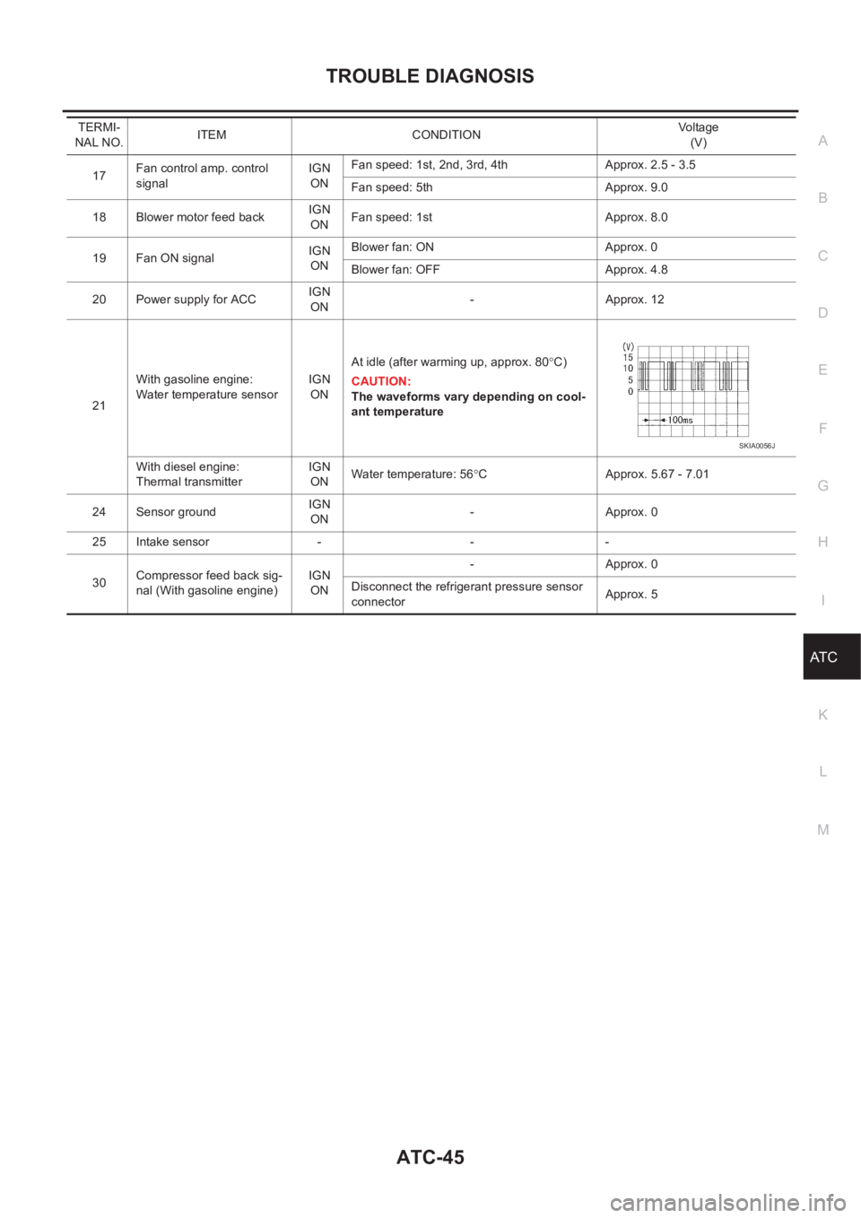
17Fan control amp. control
signalIGN
ONFan speed: 1st, 2nd, 3rd, 4th Approx. 2.5 - 3.5
Fan speed: 5th Approx. 9.0
18 Blower motor feed backIGN
ONFan speed: 1st Approx. 8.0
19 Fan ON signalIGN
ONBlower fan: ON Approx. 0
Blower fan: OFF Approx. 4.8
20 Power supply for ACCIGN
ON-Approx. 12
21With gasoline engine:
Water temperature sensorIGN
ONAt idle (after warming up, approx. 80°C)
CAUTION:
The waveforms vary depending on cool-
ant temperature
With diesel engine:
Thermal transmitterIGN
ONWater temperature: 56°C Approx. 5.67 - 7.01
24 Sensor groundIGN
ON-Approx. 0
25 Intake sensor - - -
30Compressor feed back sig-
nal (With gasoline engine)IGN
ON-Approx. 0
Disconnect the refrigerant pressure sensor
connectorApprox. 5 TERMI-
NAL NO.ITEM CONDITIONVo l ta g e
(V)
SKIA0056J
Page 3322 of 3833
ATC-46
TROUBLE DIAGNOSIS
Self-diagnosis Function
EJS001GX
DESCRIPTION
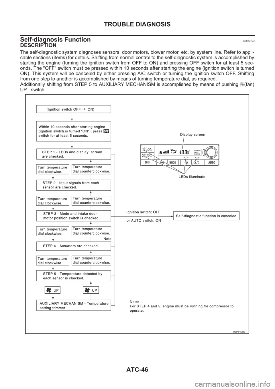
The self-diagnostic system diagnoses sensors, door motors, blower motor, etc. by system line. Refer to appli-
cable sections (items) for details. Shifting from normal control to the self-diagnostic system is accomplished by
starting the engine (turning the ignition switch from OFF to ON) and pressing OFF switch for at least 5 sec-
onds. The "OFF" switch must be pressed within 10 seconds after starting the engine (ignition switch is turned
ON). This system will be canceled by either pressing A/C switch or turning the ignition switch OFF. Shifting
from one step to another is accomplished by means of turning temperature dial, as required.
Additionally shifting from STEP 5 to AUXILIARY MECHANISM is accomplished by means of pushing (fan)
UP switch.
RJIA0490E
Page 3323 of 3833
TROUBLE DIAGNOSIS
ATC-47
C
D
E
F
G
H
I
K
L
MA
B
AT C
PROCEDURE
1.SET IN SELF-DIAGNOSTIC MODE
1. Turn ignition switch ON.
2. Set in self-diagnostic mode as follows. Within 10 seconds after starting engine (ignition switch is turned
ON.), press OFF switch for at least 5 seconds.
>> GO TO 2.
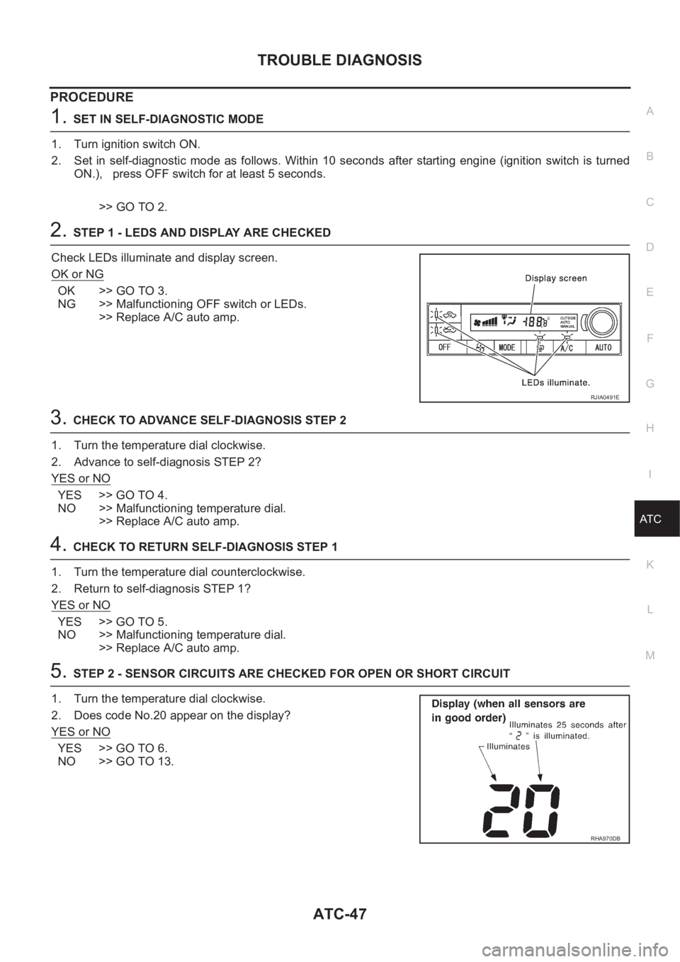
2.STEP 1 - LEDS AND DISPLAY ARE CHECKED
Check LEDs illuminate and display screen.
OK or NG
OK >> GO TO 3.
NG >> Malfunctioning OFF switch or LEDs.
>> Replace A/C auto amp.
3.CHECK TO ADVANCE SELF-DIAGNOSIS STEP 2
1. Turn the temperature dial clockwise.
2. Advance to self-diagnosis STEP 2?
YES or NO
YES >> GO TO 4.
NO >> Malfunctioning temperature dial.
>> Replace A/C auto amp.
4.CHECK TO RETURN SELF-DIAGNOSIS STEP 1
1. Turn the temperature dial counterclockwise.
2. Return to self-diagnosis STEP 1?
YES or NO
YES >> GO TO 5.
NO >> Malfunctioning temperature dial.
>> Replace A/C auto amp.
5.STEP 2 - SENSOR CIRCUITS ARE CHECKED FOR OPEN OR SHORT CIRCUIT
1. Turn the temperature dial clockwise.
2. Does code No.20 appear on the display?
YES or NO
YES >> GO TO 6.
NO >> GO TO 13.
RJIA0491E
RHA970DB
Page 3324 of 3833
ATC-48
TROUBLE DIAGNOSIS
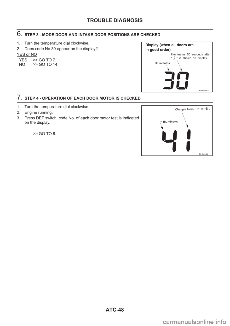
6. STEP 3 - MODE DOOR AND INTAKE DOOR POSITIONS ARE CHECKED
1. Turn the temperature dial clockwise.
2. Does code No.30 appear on the display?
YES or NO
YES >> GO TO 7.
NO >> GO TO 14.
7. STEP 4 - OPERATION OF EACH DOOR MOTOR IS CHECKED
1. Turn the temperature dial clockwise.
2. Engine running.
3. Press DEF switch, code No. of each door motor test is indicated
on the display.
>> GO TO 8.
RHA869DD
RHA495A
Page 3325 of 3833
TROUBLE DIAGNOSIS
ATC-49
C
D
E
F
G
H
I
K
L
MA
B
AT C
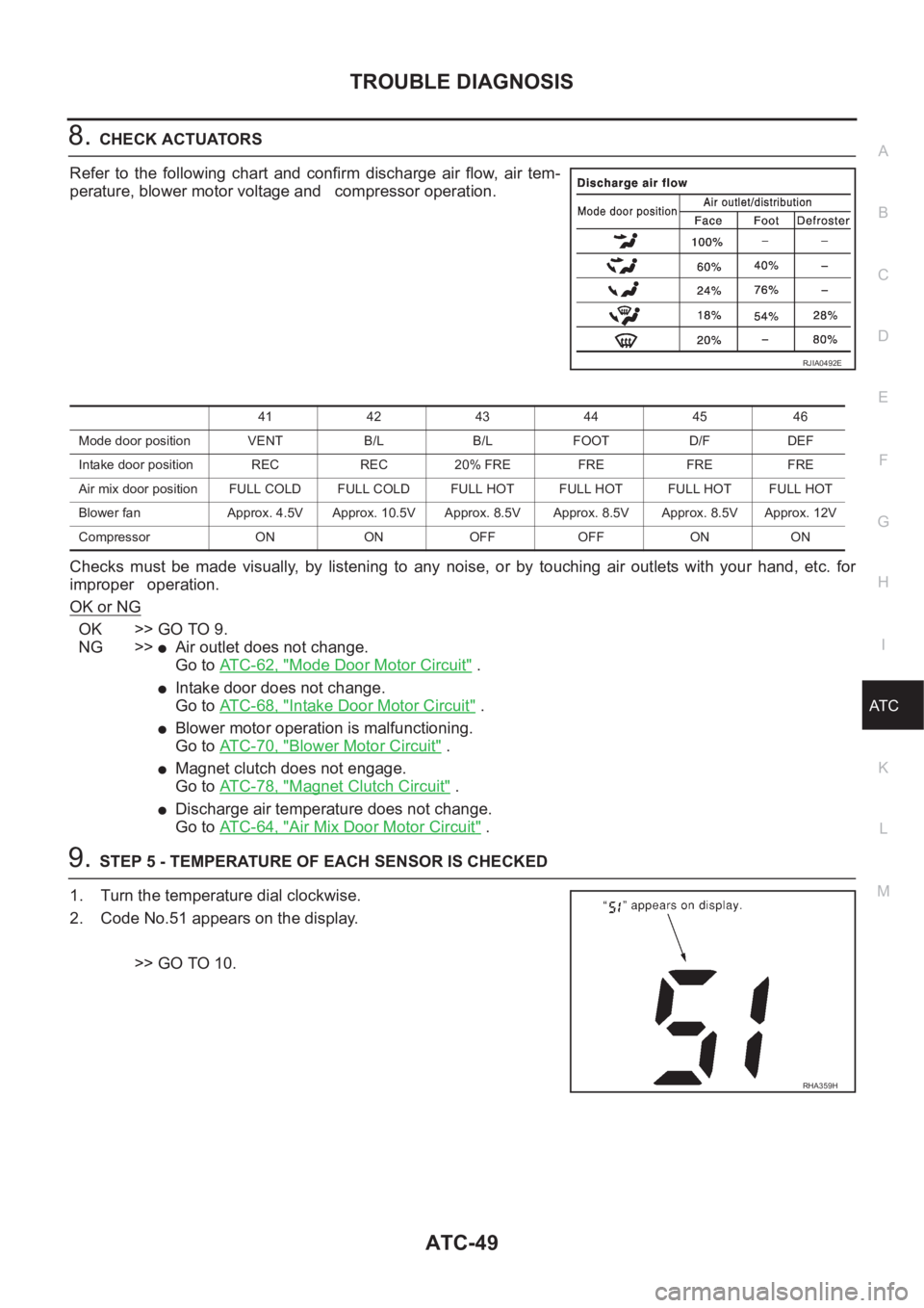
8.CHECK ACTUATORS
Refer to the following chart and confirm discharge air flow, air tem-
perature, blower motor voltage and compressor operation.
Checks must be made visually, by listening to any noise, or by touching air outlets with your hand, etc. for
improper operation.
OK or NG
OK >> GO TO 9.
NG >>
●Air outlet does not change.
Go to ATC-62, "
Mode Door Motor Circuit" .
●Intake door does not change.
Go to ATC-68, "
Intake Door Motor Circuit" .
●Blower motor operation is malfunctioning.
Go to ATC-70, "
Blower Motor Circuit" .
●Magnet clutch does not engage.
Go to ATC-78, "
Magnet Clutch Circuit" .
●Discharge air temperature does not change.
Go to ATC-64, "
Air Mix Door Motor Circuit" .
9.STEP 5 - TEMPERATURE OF EACH SENSOR IS CHECKED
1. Turn the temperature dial clockwise.
2. Code No.51 appears on the display.
>> GO TO 10.
RJIA0492E
41 42 43 44 45 46
Mode door position VENT B/L B/L FOOT D/F DEF
Intake door position REC REC 20% FRE FRE FRE FRE
Air mix door position FULL COLD FULL COLD FULL HOT FULL HOT FULL HOTFULL HOT
Blower fan Approx. 4.5V Approx. 10.5V Approx. 8.5V Approx. 8.5V Approx. 8.5V Approx. 12V
Compressor ON ON OFF OFF ON ON
RHA359H
Page 3326 of 3833
ATC-50
TROUBLE DIAGNOSIS
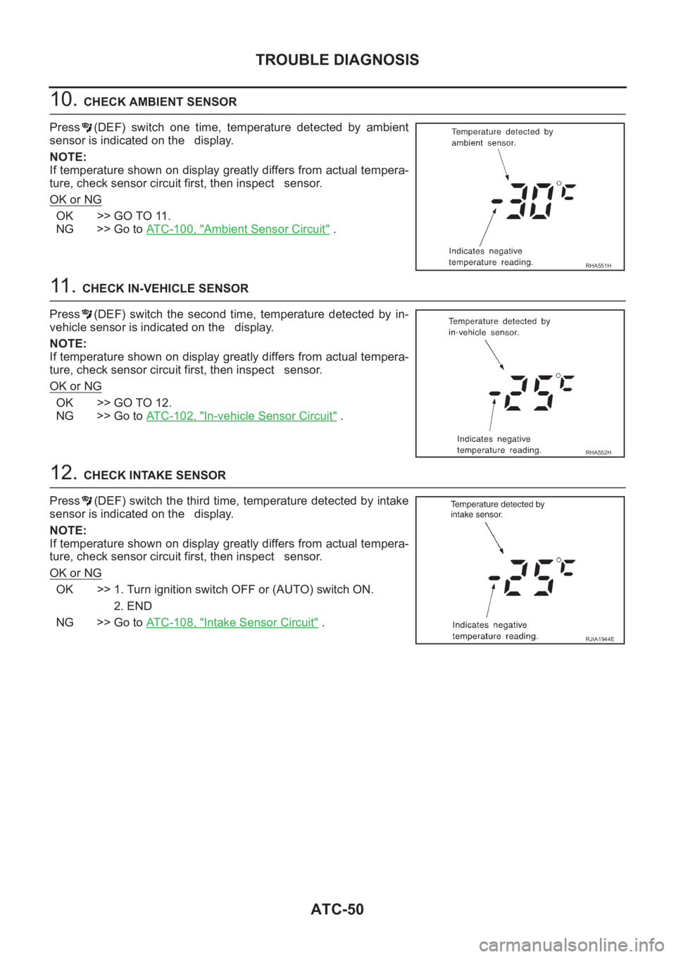
10. CHECK AMBIENT SENSOR
Press (DEF) switch one time, temperature detected by ambient
sensor is indicated on the display.
NOTE:
If temperature shown on display greatly differs from actual tempera-
ture, check sensor circuit first, then inspect sensor.
OK or NG
OK >> GO TO 11.
NG >> Go to ATC-100, "
Ambient Sensor Circuit" .
11 . CHECK IN-VEHICLE SENSOR
Press (DEF) switch the second time, temperature detected by in-
vehicle sensor is indicated on the display.
NOTE:
If temperature shown on display greatly differs from actual tempera-
ture, check sensor circuit first, then inspect sensor.
OK or NG
OK >> GO TO 12.
NG >> Go to ATC-102, "
In-vehicle Sensor Circuit" .
12. CHECK INTAKE SENSOR
Press (DEF) switch the third time, temperature detected by intake
sensor is indicated on the display.
NOTE:
If temperature shown on display greatly differs from actual tempera-
ture, check sensor circuit first, then inspect sensor.
OK or NG
OK >> 1. Turn ignition switch OFF or (AUTO) switch ON.
2. END
NG >> Go to ATC-108, "
Intake Sensor Circuit" .
RHA551H
RHA552H
RJIA1944E
Page 3327 of 3833
TROUBLE DIAGNOSIS
ATC-51
C
D
E
F
G
H
I
K
L
MA
B
AT C
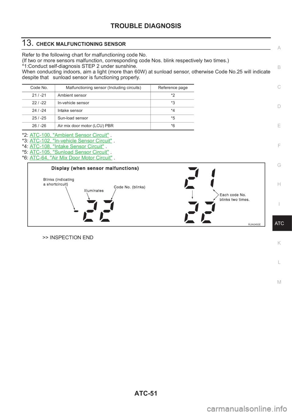
13.CHECK MALFUNCTIONING SENSOR
Refer to the following chart for malfunctioning code No.
(If two or more sensors malfunction, corresponding code Nos. blink respectively two times.)
*1:Conduct self-diagnosis STEP 2 under sunshine.
When conducting indoors, aim a light (more than 60W) at sunload sensor, otherwise Code No.25 will indicate
despite that sunload sensor is functioning properly.
*2: ATC-100, "
Ambient Sensor Circuit" .
*3: ATC-102, "
In-vehicle Sensor Circuit" .
*4: ATC-108, "
Intake Sensor Circuit" .
*5: ATC-105, "
Sunload Sensor Circuit" .
*6: AT C - 6 4 , "
Air Mix Door Motor Circuit" .
>> INSPECTION END
Code No. Malfunctioning sensor (Including circuits) Reference page
21 / -21 Ambient sensor *2
22 / -22 In-vehicle sensor *3
24 / -24 Intake sensor *4
25 / -25 Sun-load sensor *5
26 / -26 Air mix door motor (LCU) PBR *6
RJIA0493E
Page 3328 of 3833
ATC-52
TROUBLE DIAGNOSIS
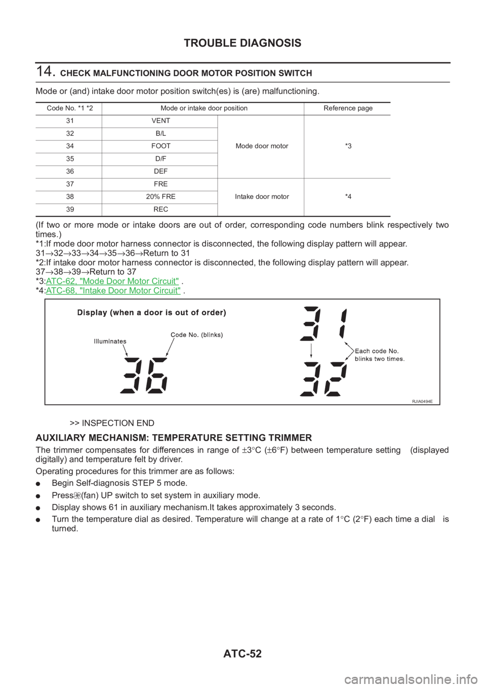
14. CHECK MALFUNCTIONING DOOR MOTOR POSITION SWITCH
Mode or (and) intake door motor position switch(es) is (are) malfunctioning.
(If two or more mode or intake doors are out of order, corresponding code numbers blink respectively two
times.)
*1:If mode door motor harness connector is disconnected, the following display pattern will appear.
31→32→33→34→35→36→Return to 31
*2:If intake door motor harness connector is disconnected, the following display pattern will appear.
37→38→39→Return to 37
*3:AT C - 6 2 , "
Mode Door Motor Circuit" .
*4:AT C - 6 8 , "
Intake Door Motor Circuit" .
>> INSPECTION END
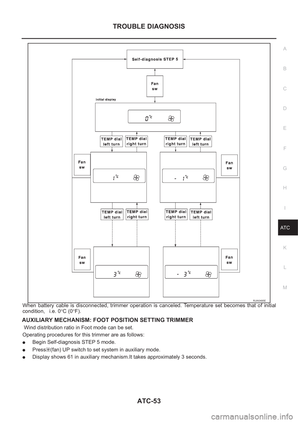
AUXILIARY MECHANISM: TEMPERATURE SETTING TRIMMER
The trimmer compensates for differences in range of ±3°C (±6°F) between temperature setting (displayed
digitally) and temperature felt by driver.
Operating procedures for this trimmer are as follows:
●Begin Self-diagnosis STEP 5 mode.
●Press (fan) UP switch to set system in auxiliary mode.
●Display shows 61 in auxiliary mechanism.It takes approximately 3 seconds.
●Turn the temperature dial as desired. Temperature will change at a rate of 1°C (2°F) each time a dial is
turned.
Code No. *1 *2 Mode or intake door position Reference page
31 VENT
Mode door motor *3 32 B/L
34 FOOT
35 D/F
36 DEF
37 FRE
Intake door motor *4 38 20% FRE
39 REC
RJIA0494E
Page 3329 of 3833
TROUBLE DIAGNOSIS
ATC-53
C
D
E
F
G
H
I
K
L
MA
B
AT C
When battery cable is disconnected, trimmer operation is canceled. Temperature set becomes that of initial
condition, i.e. 0°C (0°F).
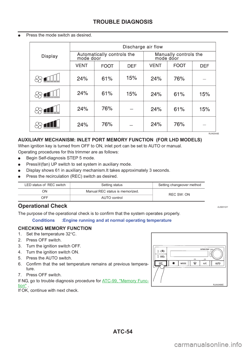
AUXILIARY MECHANISM: FOOT POSITION SETTING TRIMMER
Wind distribution ratio in Foot mode can be set.
Operating procedures for this trimmer are as follows:
●Begin Self-diagnosis STEP 5 mode.
●Press (fan) UP switch to set system in auxiliary mode.
●Display shows 61 in auxiliary mechanism.It takes approximately 3 seconds.
RJIA0495E
Page 3330 of 3833
ATC-54
TROUBLE DIAGNOSIS
●Press the mode switch as desired.
AUXILIARY MECHANISM: INLET PORT MEMORY FUNCTION (FOR LHD MODELS)
When ignition key is turned from OFF to ON, inlet port can be set to AUTO or manual.
Operating procedures for this trimmer are as follows:
●Begin Self-diagnosis STEP 5 mode.
●Press (fan) UP switch to set system in auxiliary mode.
●Display shows 61 in auxiliary mechanism.It takes approximately 3 seconds.
●Press the recirculation (REC) switch as desired.
Operational CheckEJS001GY
The purpose of the operational check is to confirm that the system operates properly.
CHECKING MEMORY FUNCTION
1. Set the temperature 32°C.
2. Press OFF switch.
3. Turn the ignition switch OFF.
4. Turn the ignition switch ON.
5. Press the AUTO switch.
6. Confirm that the set temperature remains at previous tempera-
ture.
7. Press OFF switch.
If NG, go to trouble diagnosis procedure for AT C - 9 9 , "
Memory Func-
tion" .
If OK, continue with next check.
RJIA0040E
LED status of REC switch Setting status Setting changeover method
ON Manual REC status is memorized.
REC SW: ON
OFF AUTO control
Conditions :Engine running and at normal operating temperature
RJIA0496E