NISSAN X-TRAIL 2001 Service Repair Manual
Manufacturer: NISSAN, Model Year: 2001, Model line: X-TRAIL, Model: NISSAN X-TRAIL 2001Pages: 3833, PDF Size: 39.49 MB
Page 3371 of 3833
TROUBLE DIAGNOSIS
ATC-95
C
D
E
F
G
H
I
K
L
MA
B
AT C
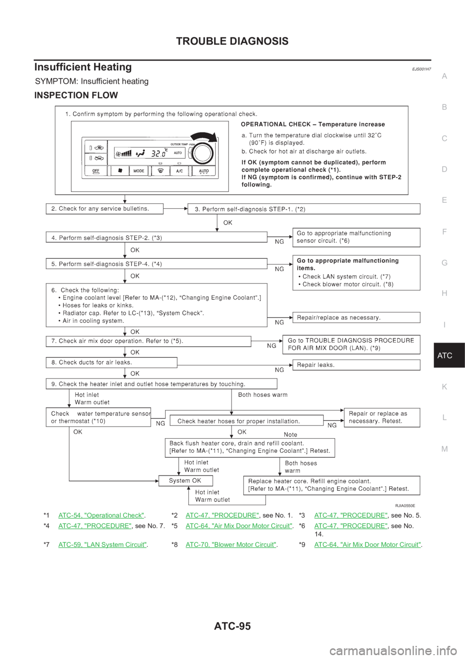
Insufficient HeatingEJS001H7
SYMPTOM: Insufficient heating
INSPECTION FLOW
*1ATC-54, "Operational Check".*2ATC-47, "PROCEDURE", see No. 1. *3AT C - 4 7 , "PROCEDURE", see No. 5.
*4ATC-47, "
PROCEDURE", see No. 7. *5ATC-64, "Air Mix Door Motor Circuit".*6AT C - 4 7 , "PROCEDURE", see No.
14.
*7ATC-59, "
LAN System Circuit".*8ATC-70, "Blower Motor Circuit".*9AT C - 6 4 , "Air Mix Door Motor Circuit".
RJIA0550E
Page 3372 of 3833
ATC-96
TROUBLE DIAGNOSIS
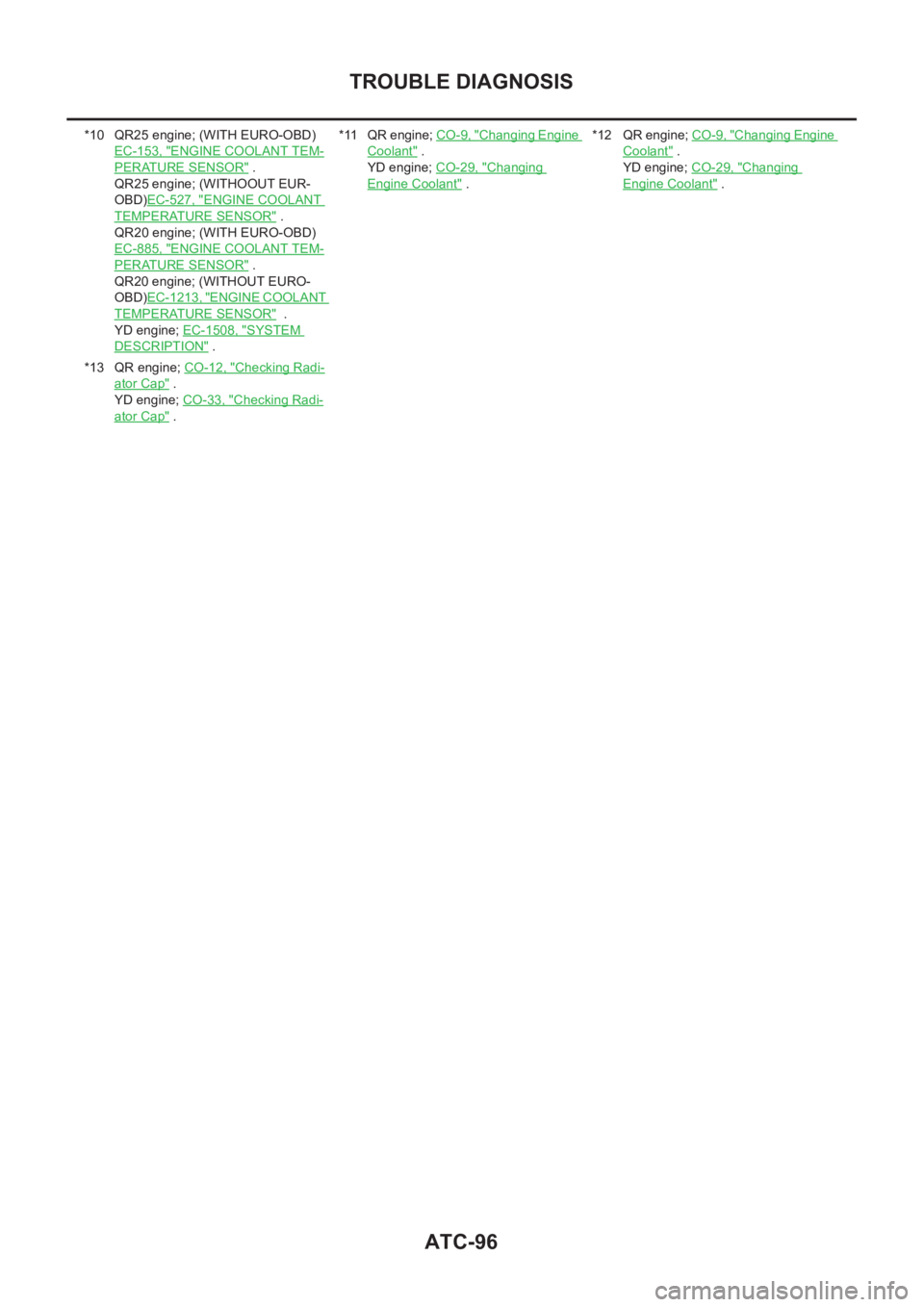
*10 QR25 engine; (WITH EURO-OBD)
EC-153, "
ENGINE COOLANT TEM-
PERATURE SENSOR" .
QR25 engine; (WITHOOUT EUR-
OBD)EC-527, "
ENGINE COOLANT
TEMPERATURE SENSOR" .
QR20 engine; (WITH EURO-OBD)
EC-885, "
ENGINE COOLANT TEM-
PERATURE SENSOR" .
QR20 engine; (WITHOUT EURO-
OBD)EC-1213, "
ENGINE COOLANT
TEMPERATURE SENSOR" .
YD engine; EC-1508, "
SYSTEM
DESCRIPTION" .*11 QR engine; CO-9, "
Changing Engine
Coolant" .
YD engine; CO-29, "
Changing
Engine Coolant" .*12 QR engine; CO-9, "
Changing Engine
Coolant" .
YD engine; CO-29, "
Changing
Engine Coolant" .
*13 QR engine; CO-12, "
Checking Radi-
ator Cap" .
YD engine; CO-33, "
Checking Radi-
ator Cap" .
Page 3373 of 3833
TROUBLE DIAGNOSIS
ATC-97
C
D
E
F
G
H
I
K
L
MA
B
AT C
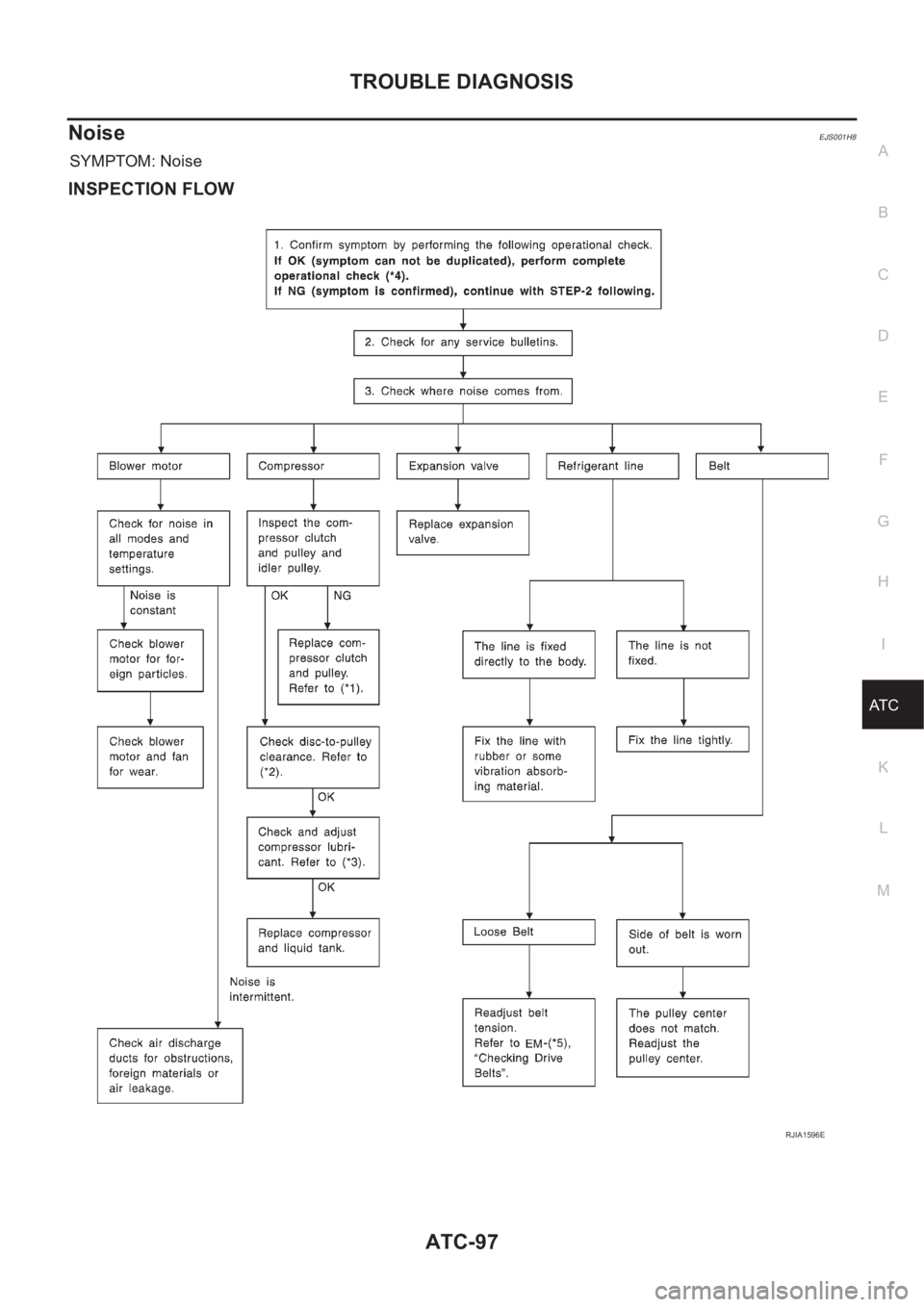
NoiseEJS001H8
SYMPTOM: Noise
INSPECTION FLOW
RJIA1596E
Page 3374 of 3833
ATC-98
TROUBLE DIAGNOSIS
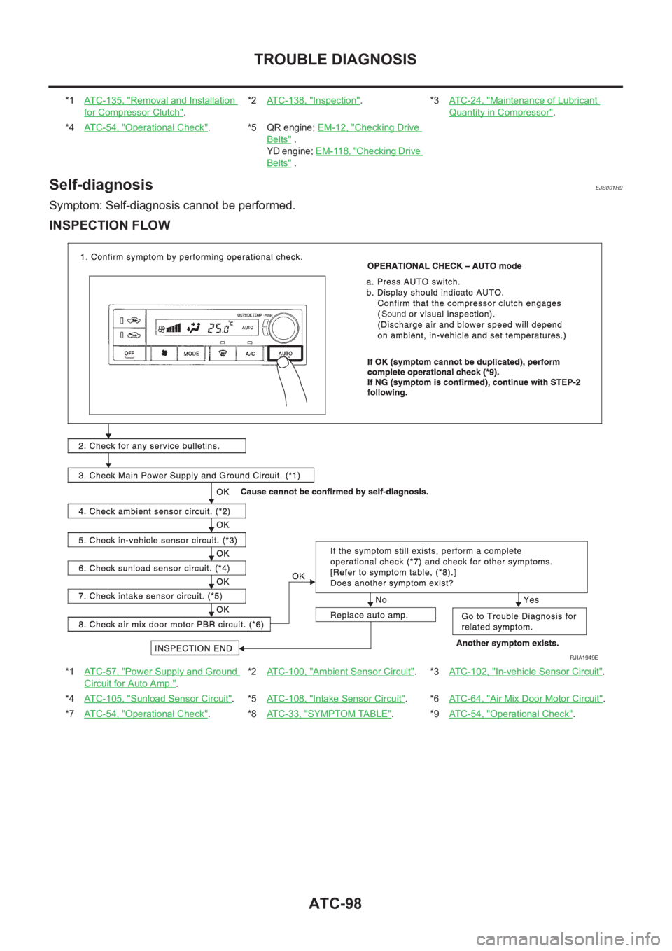
Self-diagnosis
EJS001H9
Symptom: Self-diagnosis cannot be performed.
INSPECTION FLOW
*1ATC-135, "Removal and Installation
for Compressor Clutch".*2ATC-138, "
Inspection".*3AT C - 2 4 , "Maintenance of Lubricant
Quantity in Compressor".
*4ATC-54, "
Operational Check".*5QR engine; EM-12, "Checking Drive
Belts" .
YD engine; EM-118, "
Checking Drive
Belts" .
*1ATC-57, "
Power Supply and Ground
Circuit for Auto Amp.".*2AT C - 1 0 0 , "
Ambient Sensor Circuit".*3ATC-102, "In-vehicle Sensor Circuit".
*4ATC-105, "
Sunload Sensor Circuit".*5ATC-108, "Intake Sensor Circuit".*6AT C - 6 4 , "Air Mix Door Motor Circuit".
*7ATC-54, "
Operational Check".*8ATC-33, "SYMPTOM TABLE".*9AT C - 5 4 , "Operational Check".
RJIA1949E
Page 3375 of 3833
TROUBLE DIAGNOSIS
ATC-99
C
D
E
F
G
H
I
K
L
MA
B
AT C
Memory FunctionEJS001HA
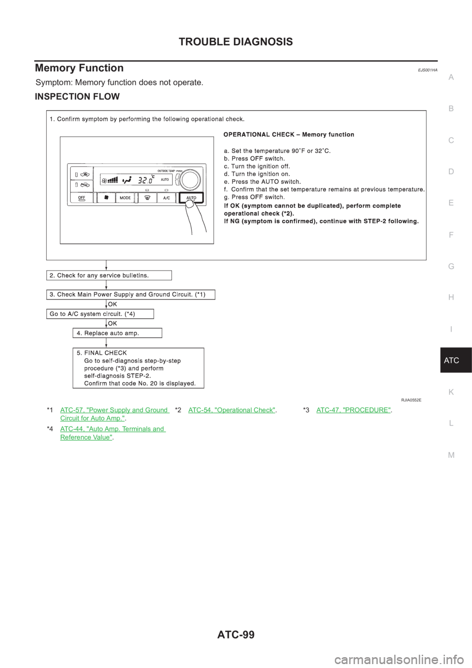
Symptom: Memory function does not operate.
INSPECTION FLOW
*1AT C - 5 7 , "Power Supply and Ground
Circuit for Auto Amp.".*2AT C - 5 4 , "
Operational Check".*3AT C - 4 7 , "PROCEDURE".
*4AT C - 4 4 , "
Auto Amp. Terminals and
Reference Value".
RJIA0552E
Page 3376 of 3833
ATC-100
TROUBLE DIAGNOSIS
Ambient Sensor Circuit
EJS001HB
COMPONENT DESCRIPTION
Ambient Sensor
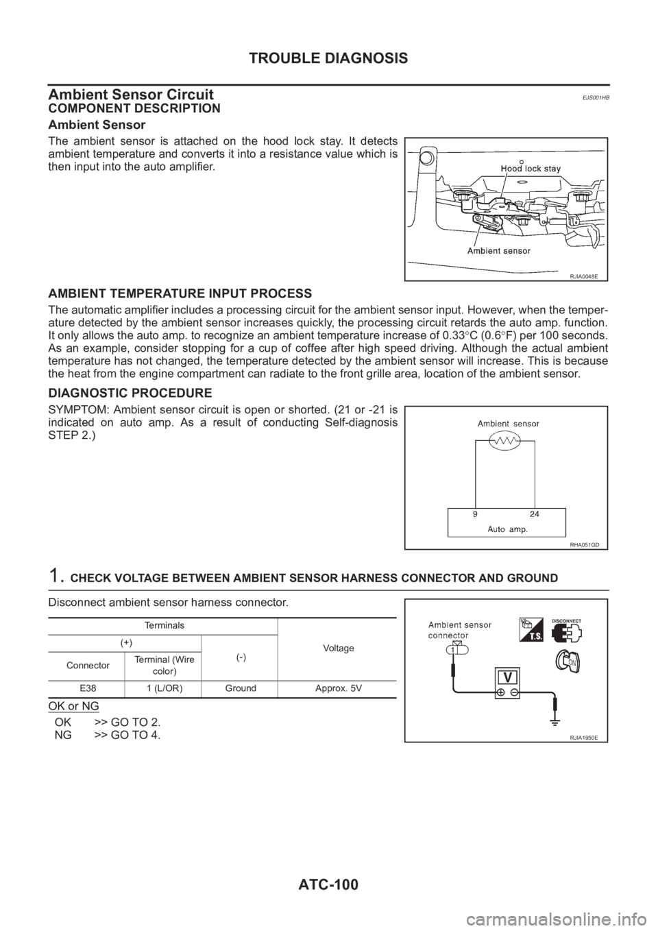
The ambient sensor is attached on the hood lock stay. It detects
ambient temperature and converts it into a resistance value which is
then input into the auto amplifier.
AMBIENT TEMPERATURE INPUT PROCESS
The automatic amplifier includes a processing circuit for the ambient sensor input. However, when the temper-
ature detected by the ambient sensor increases quickly, the processing circuit retards the auto amp. function.
It only allows the auto amp. to recognize an ambient temperature increase of 0.33°C (0.6°F) per 100 seconds.
As an example, consider stopping for a cup of coffee after high speed driving. Although the actual ambient
temperature has not changed, the temperature detected by the ambient sensor will increase. This is because
the heat from the engine compartment can radiate to the front grille area, location of the ambient sensor.
DIAGNOSTIC PROCEDURE
SYMPTOM: Ambient sensor circuit is open or shorted. (21 or -21 is
indicated on auto amp. As a result of conducting Self-diagnosis
STEP 2.)
1. CHECK VOLTAGE BETWEEN AMBIENT SENSOR HARNESS CONNECTOR AND GROUND
Disconnect ambient sensor harness connector.
OK or NG
OK >> GO TO 2.
NG >> GO TO 4.
RJIA0048E
RHA051GD
Terminals
Voltage (+)
(-)
ConnectorTerminal (Wire
color)
E38 1 (L/OR) Ground Approx. 5V
RJIA1950E
Page 3377 of 3833
TROUBLE DIAGNOSIS
ATC-101
C
D
E
F
G
H
I
K
L
MA
B
AT C
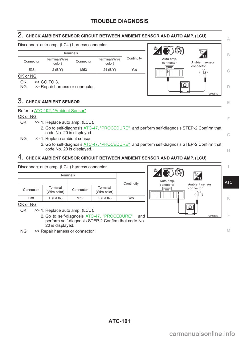
2.CHECK AMBIENT SENSOR CIRCUIT BETWEEN AMBIENT SENSOR AND AUTO AMP. (LCU)
Disconnect auto amp. (LCU) harness connector.
OK or NG
OK >> GO TO 3.
NG >> Repair harness or connector.
3.CHECK AMBIENT SENSOR
Refer to ATC-102, "
Ambient Sensor"
OK or NG
OK >> 1. Replace auto amp. (LCU).
2. Go to self-diagnosis AT C - 4 7 , "
PROCEDURE" and perform self-diagnosis STEP-2.Confirm that
code No. 20 is displayed.
NG >> 1. Replace ambient sensor.
2. Go to self-diagnosis AT C - 4 7 , "
PROCEDURE" and perform self-diagnosis STEP-2.Confirm that
code No. 20 is displayed.
4.CHECK AMBIENT SENSOR CIRCUIT BETWEEN AMBIENT SENSOR AND AUTO AMP. (LCU)
Disconnect auto amp. (LCU) harness connector.
OK or NG
OK >> 1. Replace auto amp. (LCU).
2. Go to self-diagnosis AT C - 4 7 , "
PROCEDURE" and
perform self-diagnosis STEP-2.Confirm that code No.
20 is displayed.
NG >> Repair harness or connector.
Te r m i n a l s
Continuity
ConnectorTerminal (Wire
color)ConnectorTerminal (Wire
color)
E38 2 (B/Y) M53 24 (B/Y) Yes
RJIA1951E
Terminals
Continuity
ConnectorTerminal
(Wire color)ConnectorTe r m i n a l
(Wire color)
E38 1 (L/OR) M52 9 (L/OR) Yes
RJIA1952E
Page 3378 of 3833
ATC-102
TROUBLE DIAGNOSIS
COMPONENT INSPECTION
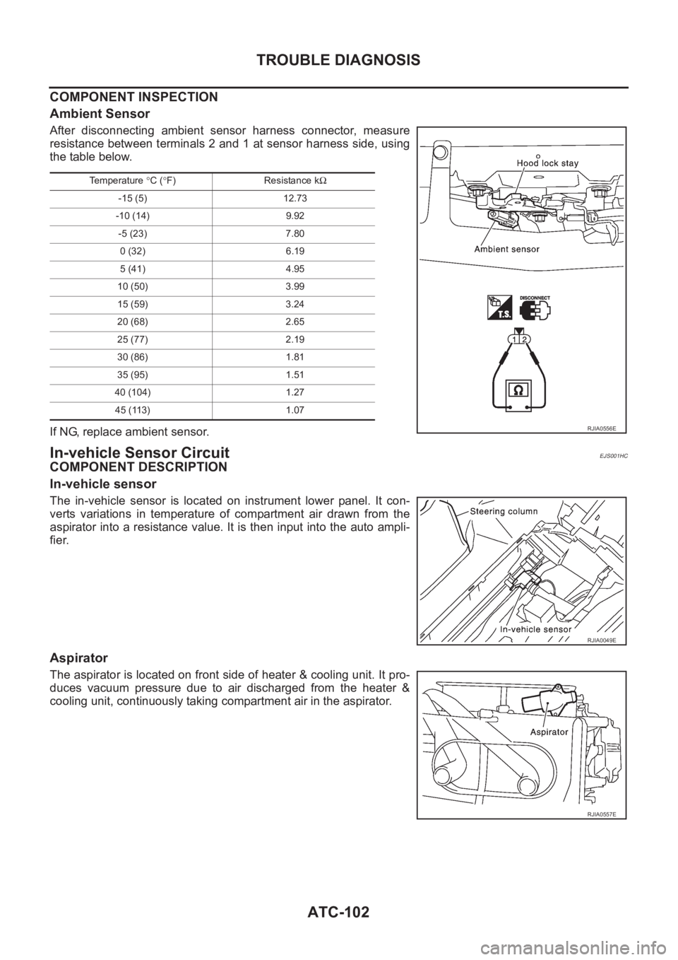
Ambient Sensor
After disconnecting ambient sensor harness connector, measure
resistance between terminals 2 and 1 at sensor harness side, using
the table below.
If NG, replace ambient sensor.
In-vehicle Sensor CircuitEJS001HC
COMPONENT DESCRIPTION
In-vehicle sensor
The in-vehicle sensor is located on instrument lower panel. It con-
verts variations in temperature of compartment air drawn from the
aspirator into a resistance value. It is then input into the auto ampli-
fier.
Aspirator
The aspirator is located on front side of heater & cooling unit. It pro-
duces vacuum pressure due to air discharged from the heater &
cooling unit, continuously taking compartment air in the aspirator.
Temperature °C (°F) Resistance kΩ
-15 (5) 12.73
-10 (14) 9.92
-5 (23) 7.80
0 (32) 6.19
5 (41) 4.95
10 (50) 3.99
15 (59) 3.24
20 (68) 2.65
25 (77) 2.19
30 (86) 1.81
35 (95) 1.51
40 (104) 1.27
45 (113) 1.07
RJIA0556E
RJIA0049E
RJIA0557E
Page 3379 of 3833
TROUBLE DIAGNOSIS
ATC-103
C
D
E
F
G
H
I
K
L
MA
B
AT C
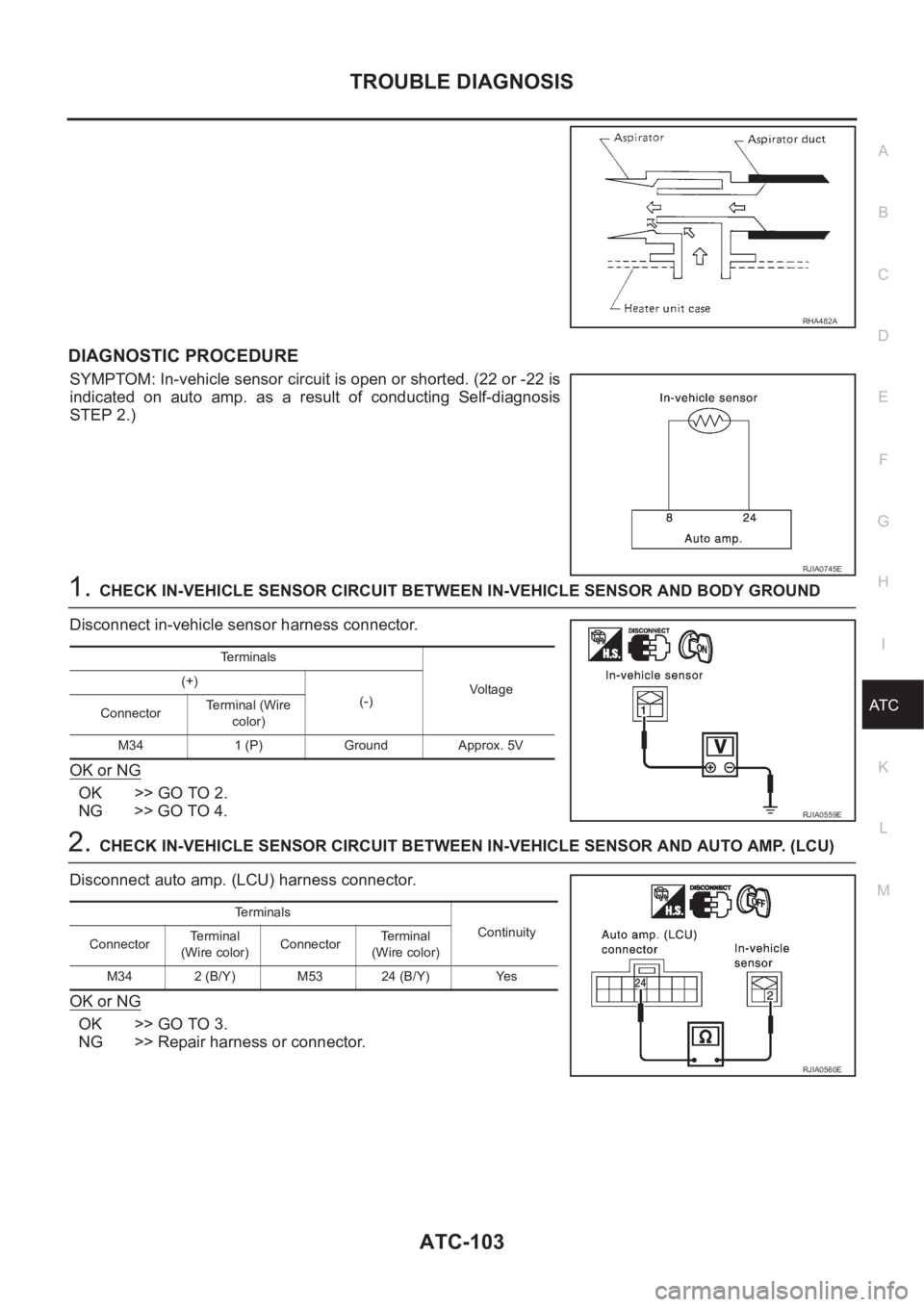
DIAGNOSTIC PROCEDURE
SYMPTOM: In-vehicle sensor circuit is open or shorted. (22 or -22 is
indicated on auto amp. as a result of conducting Self-diagnosis
STEP 2.)
1.CHECK IN-VEHICLE SENSOR CIRCUIT BETWEEN IN-VEHICLE SENSOR AND BODY GROUND
Disconnect in-vehicle sensor harness connector.
OK or NG
OK >> GO TO 2.
NG >> GO TO 4.
2.CHECK IN-VEHICLE SENSOR CIRCUIT BETWEEN IN-VEHICLE SENSOR AND AUTO AMP. (LCU)
Disconnect auto amp. (LCU) harness connector.
OK or NG
OK >> GO TO 3.
NG >> Repair harness or connector.
RHA482A
RJIA0745E
Terminals
Voltag e (+)
(-)
ConnectorTerminal (Wire
color)
M34 1 (P) Ground Approx. 5V
RJIA0559E
Te r m i n a l s
Continuity
ConnectorTerminal
(Wire color)ConnectorTerminal
(Wire color)
M34 2 (B/Y) M53 24 (B/Y) Yes
RJIA0560E
Page 3380 of 3833
ATC-104
TROUBLE DIAGNOSIS
3. CHECK IN-VEHICLE SENSOR
Refer to ATC-104, "
In-vehicle Sensor"
OK or NG
OK >> 1. Replace auto amp.
2. Go to self-diagnosis AT C - 4 7 , "
PROCEDURE" and perform self-diagnosis STEP-2. Confirm
that code No. 20 is displayed.
NG >> 1. Replace in-vehicle sensor.
2. Go to self-diagnosis AT C - 4 7 , "
PROCEDURE" and perform self-diagnosis STEP-2. Confirm
that code No. 20 is displayed.
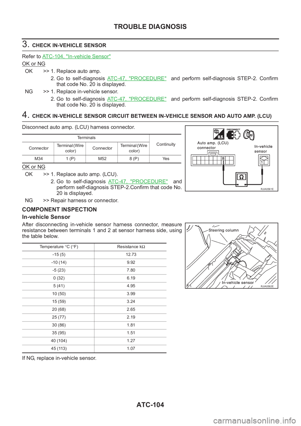
4. CHECK IN-VEHICLE SENSOR CIRCUIT BETWEEN IN-VEHICLE SENSOR AND AUTO AMP. (LCU)
Disconnect auto amp. (LCU) harness connector.
OK or NG
OK >> 1. Replace auto amp. (LCU).
2. Go to self-diagnosis AT C - 4 7 , "
PROCEDURE" and
perform self-diagnosis STEP-2.Confirm that code No.
20 is displayed.
NG >> Repair harness or connector.
COMPONENT INSPECTION
In-vehicle Sensor
After disconnecting in-vehicle sensor harness connector, measure
resistance between terminals 1 and 2 at sensor harness side, using
the table below.
If NG, replace in-vehicle sensor.
Terminals
Continuity
ConnectorTerminal (Wire
color)ConnectorTerminal (Wire
color)
M34 1 (P) M52 8 (P) Yes
RJIA0561E
Temperature °C (°F) Resistance kΩ
-15 (5) 12.73
-10 (14) 9.92
-5 (23) 7.80
0 (32) 6.19
5 (41) 4.95
10 (50) 3.99
15 (59) 3.24
20 (68) 2.65
25 (77) 2.19
30 (86) 1.81
35 (95) 1.51
40 (104) 1.27
45 (113) 1.07
RJIA0562E