wiring NISSAN X-TRAIL 2001 Service Owner's Guide
[x] Cancel search | Manufacturer: NISSAN, Model Year: 2001, Model line: X-TRAIL, Model: NISSAN X-TRAIL 2001Pages: 3833, PDF Size: 39.49 MB
Page 365 of 3833
EC-15
C
D
E
F
G
H
I
J
K
L
M
ECA Component Inspection ........................................1208
Removal and Installation .....................................1208
DTC P0117, P0118 ECT SENSOR ........................1209
Component Description .......................................1209
On Board Diagnosis Logic ..................................1209
DTC Confirmation Procedure ..............................1210
Wiring Diagram ...................................................1211
Diagnostic Procedure ..........................................1212
Component Inspection ........................................1213
Removal and Installation .....................................1213
DTC P0120 TP SENSOR .......................................1214
Component Description .......................................1214
CONSULT-II Reference Value in Data Monitor Mode
1214
ECM Terminals and Reference Value .................1214
On Board Diagnosis Logic ..................................1215
DTC Confirmation Procedure ..............................1215
Wiring Diagram ...................................................1218
Diagnostic Procedure ..........................................1219
Component Inspection ........................................1221
Remove and Installation ......................................1221
DTC P0121 APP SENSOR ....................................1222
Component Description .......................................1222
CONSULT-II Reference Value in Data Monitor Mode
1222
ECM Terminals and Reference Value .................1222
On Board Diagnosis Logic ..................................1223
DTC Confirmation Procedure ..............................1223
Wiring Diagram ...................................................1225
Diagnostic Procedure ..........................................1226
Component Inspection ........................................1228
Remove and Installation ......................................1228
DTC P0134 HO2S1 ................................................1229
Component Description .......................................1229
CONSULT-II Reference Value in Data Monitor Mode
1229
ECM Terminals and Reference Value .................1229
On Board Diagnosis Logic ..................................1230
Overall Function Check .......................................1230
Wiring Diagram ...................................................1231
Diagnostic Procedure ..........................................1232
Component Inspection ........................................1233
Removal and Installation .....................................1234
DTC P0327, P0328 KS ..........................................1235
Component Description .......................................1235
ECM Terminals and Reference Value .................1235
On Board Diagnosis Logic ..................................1235
DTC Confirmation Procedure ..............................1235
Wiring Diagram ...................................................1237
Diagnostic Procedure ..........................................1238
Component Inspection ........................................1239
Removal and Installation .....................................1239
DTC P0335 CKP SENSOR (POS) .........................1240
Component Description .......................................1240
CONSULT-II Reference Value in Data Monitor Mode
1240
ECM Terminals and Reference Value .................1240
On Board Diagnosis Logic ..................................1241
DTC Confirmation Procedure ..............................1241Wiring Diagram ....................................................1242
Diagnostic Procedure ..........................................1243
Component Inspection .........................................1245
Removal and Installation .....................................1245
DTC P0340 CMP SENSOR (PHASE) ....................1246
Component Description .......................................1246
ECM Terminals and Reference Value ..................1246
On Board Diagnosis Logic ...................................1246
DTC Confirmation Procedure ..............................1247
Wiring Diagram ....................................................1248
Diagnostic Procedure ..........................................1249
Component Inspection .........................................1251
Removal and Installation .....................................1251
DTC P0500 VSS .....................................................1252
Component Description .......................................1252
ECM Terminals and Reference Value ..................1252
On Board Diagnosis Logic ...................................1252
DTC Confirmation Procedure ..............................1252
Overall Function Check .......................................1253
Wiring Diagram ....................................................1254
Diagnostic Procedure ..........................................1256
DTC P0550 PSP SENSOR ....................................1257
Component Description .......................................1257
CONSULT-II Reference Value in Data Monitor Mode
1257
ECM Terminals and Reference Value ..................1257
On Board Diagnosis Logic ...................................1257
DTC Confirmation Procedure ..............................1257
Wiring Diagram ....................................................1259
Diagnostic Procedure ..........................................1260
Component Inspection .........................................1261
DTC P0605 ECM ....................................................1262
Component Description .......................................1262
On Board Diagnosis Logic ...................................1262
DTC Confirmation Procedure ..............................1262
Diagnostic Procedure ..........................................1264
DTC P0650 MI ........................................................1265
Component Description .......................................1265
On Board Diagnosis Logic ...................................1265
DTC Confirmation Procedure ..............................1265
Overall Function Check .......................................1265
Wiring Diagram ....................................................1266
Diagnostic Procedure ..........................................1267
DTC P1065 ECM POWER SUPPLY ......................1269
Component Description .......................................1269
On Board Diagnosis Logic ...................................1269
DTC Confirmation Procedure ..............................1269
Wiring Diagram ....................................................1270
Diagnostic Procedure ..........................................1271
DTC P1121 ELECTRIC THROTTLE CONTROL
ACTUATOR ............................................................1273
Description ...........................................................1273
On Board Diagnosis Logic ...................................1273
DTC Confirmation Procedure ..............................1273
Diagnostic Procedure ..........................................1274
DTC P1122 ELECTRIC THROTTLE CONTROL
FUNCTION .............................................................1275
Description ...........................................................1275
ECM Terminals and Reference Value ..................1275
Page 366 of 3833
EC-16
On Board Diagnosis Logic ...................................1275
DTC Confirmation Procedure ..............................1276
Wiring Diagram ....................................................1277
Diagnostic Procedure ..........................................1278
Component Inspection .........................................1280
DTC P1123 THROTTLE CONTROL MOTOR RELAY 1281
Component Description .......................................1281
CONSULT-II Reference Value in Data Monitor Mode
1281
ECM Terminals and Reference Value ..................1281
On Board Diagnosis Logic ...................................1281
DTC Confirmation Procedure ..............................1281
Wiring Diagram ....................................................1283
Diagnostic Procedure ..........................................1284
Component Inspection .........................................1285
DTC P1212 ESP/TCS/ABS COMMUNICATION
LINE ........................................................................1286
Description ...........................................................1286
On Board Diagnosis Logic ...................................1286
DTC Confirmation Procedure ..............................1286
Diagnostic Procedure ..........................................1286
DTC P1217 ENGINE OVER TEMPERATURE .......1287
System Description ..............................................1287
CONSULT-II Reference Value in Data Monitor Mode
1287
ECM Terminals and Reference Value ..................1288
On Board Diagnosis Logic ...................................1288
Overall Function Check .......................................1289
Wiring Diagram ....................................................1291
Diagnostic Procedure ..........................................1292
Main 12 Causes of Overheating ..........................1299
Component Inspection .........................................1300
DTC P1805 BRAKE SWITCH ................................1301
Description ...........................................................1301
CONSULT-II Reference Value in Data Monitor Mode
1301
ECM Terminals and Reference Value ..................1301
On Board Diagnosis Logic ...................................1301
FAIL-SAFE MODE ...............................................1301
DTC Confirmation Procedure ..............................1301
Wiring Diagram ....................................................1303
Diagnostic Procedure ..........................................1304
Component Inspection .........................................1305
HO2S1 HEATER ....................................................1307
Description ...........................................................1307
CONSULT-II Reference Value in Data Monitor Mode
1307
ECM Terminals and Reference Value ..................1307
Wiring Diagram ....................................................1308
Diagnostic Procedure ..........................................1309
Component Inspection .........................................1311
Removal and Installation .....................................1311
HO2S2 HEATER ....................................................1312
Description ...........................................................1312
CONSULT-II Reference Value in Data Monitor Mode
1312
ECM Terminals and Reference Value ..................1312
Wiring Diagram ....................................................1313
Diagnostic Procedure ..........................................1314Component Inspection .........................................1315
Removal and Installation ......................................1315
IAT SENSOR ..........................................................1316
Component Description .......................................1316
Wiring Diagram ....................................................1317
Diagnostic Procedure ........................................... 1318
Component Inspection .........................................1319
Removal and Installation ......................................1319
HO2S1 ....................................................................1320
Component Description .......................................1320
CONSULT-II Reference Value in Data Monitor Mode
1320
ECM Terminals and Reference Value ..................1320
Wiring Diagram ....................................................1321
Diagnostic Procedure ........................................... 1322
Component Inspection .........................................1323
Removal and Installation ......................................1325
HO2S2 ....................................................................1326
Component Description .......................................1326
CONSULT-II Reference Value in Data Monitor Mode
1326
ECM Terminals and Reference Value ..................1326
Wiring Diagram ....................................................1327
Diagnostic Procedure ........................................... 1328
Component Inspection .........................................1329
Removal and Installation ......................................1330
IGNITION SIGNAL .................................................1331
Component Description .......................................1331
ECM Terminals and Reference Value ..................1331
Wiring Diagram ....................................................1332
Diagnostic Procedure ........................................... 1334
Component Inspection .........................................1338
Removal and Installation ......................................1339
EVAP CANISTER PURGE VOLUME CONTROL
SOLENOID VALVE ................................................. 1340
Description ...........................................................1340
CONSULT-II Reference Value in Data Monitor Mode
1340
ECM Terminals and Reference Value ..................1340
Wiring Diagram ....................................................1342
Diagnostic Procedure ........................................... 1343
Component Inspection .........................................1346
Removal and Installation ......................................1346
IVT CONTROL SOLENOID VALVE .......................1347
Description ...........................................................1347
CONSULT-II Reference Value in Data Monitor Mode
1347
ECM Terminals and Reference Value ..................1348
Wiring Diagram ....................................................1349
Diagnostic Procedure ........................................... 1350
Component Inspection .........................................1352
Removal and Installation ......................................1352
PNP SWITCH .........................................................1353
Component Description .......................................1353
CONSULT-II Reference Value in Data Monitor Mode
1353
ECM Terminals and Reference Value ..................1353
Wiring Diagram ....................................................1354
Diagnostic Procedure ........................................... 1355
Page 367 of 3833
EC-17
C
D
E
F
G
H
I
J
K
L
M
ECA INJECTOR CIRCUIT ..............................................1357
Component Description .......................................1357
CONSULT-II Reference Value in Data Monitor Mode
1357
ECM Terminals and Reference Value .................1357
Wiring Diagram ...................................................1358
Diagnostic Procedure ..........................................1359
Component Inspection ........................................1361
Removal and Installation .....................................1361
START SIGNAL .....................................................1362
CONSULT-II Reference Value in Data Monitor Mode
1362
ECM Terminals and Reference Value .................1362
Wiring Diagram ...................................................1363
Diagnostic Procedure ..........................................1364
FUEL PUMP CIRCUIT ...........................................1366
Description ..........................................................1366
CONSULT-II Reference Value in Data Monitor Mode
1366
ECM Terminals and Reference Value .................1366
Wiring Diagram ...................................................1368
Diagnostic Procedure ..........................................1369
Component Inspection ........................................1371
Removal and Installation .....................................1372
REFRIGERANT PRESSURE SENSOR ................1373
Component Description .......................................1373
ECM Terminals and Reference Value .................1373
Wiring Diagram ...................................................1374
Diagnostic Procedure ..........................................1375
Removal and Installation .....................................1376
ELECTRICAL LOAD SIGNAL ...............................1377
CONSULT-II Reference Value in Data Monitor Mode
1377
ECM Terminals and Reference Value .................1377
Wiring Diagram ...................................................1378
Diagnostic Procedure ..........................................1380
DATA LINK CONNECTOR ....................................1385
Wiring Diagram ...................................................1385
EVAPORATIVE EMISSION SYSTEM ....................1386
Description ..........................................................1386
Component Inspection ........................................1388
POSITIVE CRANKCASE VENTILATION ..............1389
Description ..........................................................1389
Component Inspection ........................................1389
SERVICE DATA AND SPECIFICATIONS (SDS) ...1391
Fuel Pressure ......................................................1391
Idle Speed and Ignition Timing ............................1391
Calculated Load Value ........................................1391
Mass Air Flow Sensor .........................................1391
Intake Air Temperature Sensor ...........................1391
Engine Coolant Temperature Sensor ..................1391
Heated Oxygen Sensor 1 Heater ........................1391
Heated Oxygen sensor 2 Heater .........................1391
Crankshaft Position Sensor (POS) ......................1391
Camshaft Position Sensor (PHASE) ...................1391
Throttle Control Motor ......................................... 1392
Injector ................................................................1392
Fuel Pump ...........................................................1392
YD
INDEX FOR DTC ....................................................1393
Alphabetical Index ...............................................1393
DTC No. Index .....................................................1393
PRECAUTIONS .....................................................1395
Precautions for Supplemental Restraint System
(SRS) “AIR BAG” and “SEAT BELT PRE-TEN-
SIONER” ..............................................................1395
Precautions ..........................................................1395
Wiring Diagrams and Trouble Diagnosis .............1397
ENGINE CONTROL SYSTEM ...............................1398
System Diagram ..................................................1398
System Chart .......................................................1399
Fuel Injection Control System ..............................1399
Fuel Injection Timing Control System ..................1401
Air Conditioning Cut Control ................................1401
F u e l C u t C o n t r o l ( A t N o L o a d & H i g h E n g i n e S p e e d ) 1401
Crankcase Ventilation System .............................1402
CAN Communication ...........................................1402
BASIC SERVICE PROCEDURE ............................1404
Fuel Filter .............................................................1404
Accelerator Pedal Released Position Learning ...1404
Fuel Pressure Relief Valve ..................................1405
ON BOARD DIAGNOSTIC (OBD) SYSTEM .........1406
DTC and MI Detection Logic ...............................1406
Diagnostic Trouble Code (DTC) ..........................1406
NATS (Nissan Anti-theft System) ........................1406
Malfunction Indicator (MI) ....................................1407
TROUBLE DIAGNOSIS .........................................1409
Trouble Diagnosis Introduction ............................1409
Basic Inspection ..................................................1412
Symptom Matrix Chart .........................................1416
Engine Control Component Parts Location .........1420
Circuit Diagram ....................................................1423
ECM Harness Connector Terminal Layout ..........1425
ECM Terminals And Reference Value .................1425
CONSULT-II Function ..........................................1431
CONSULT-II Reference Value in Data Monitor Mode
1437
Major Sensor Reference Graph in Data Monitor
Mode ....................................................................1440
TROUBLE DIAGNOSIS FOR INTERMITTENT INCI-
DENT ......................................................................1441
Description ...........................................................1441
Diagnostic Procedure ..........................................1441
POWER SUPPLY CIRCUIT FOR ECM ..................1442
ECM Terminals and Reference Value ..................1442
Wiring Diagram ....................................................1443
Diagnostic Procedure ..........................................1444
Component Inspection .........................................1447
DTC U1000 CAN COMMUNICATION LINE ...........1448
Description ...........................................................1448
On Board Diagnosis Logic ...................................1448
DTC Confirmation Procedure ..............................1448
Wiring Diagram ....................................................1449
Diagnostic Procedure ..........................................1450
DTC P0100 MASS AIR FLOW SENSOR (MAFS) .1451
Component Description .......................................1451
Page 368 of 3833
EC-18
CONSULT-II Reference Value in Data Monitor Mode
1451
ECM Terminals and Reference Value ..................1451
On Board Diagnosis Logic ...................................1452
DTC Confirmation Procedure ..............................1452
Wiring Diagram ....................................................1453
Diagnostic Procedure ..........................................1454
Component Inspection .........................................1455
Removal and Installation .....................................1455
DTC P0115 ENGINE COOLANT TEMPERATURE
(ECT) SENSOR (CIRCUIT) ....................................1456
Description ...........................................................1456
On Board Diagnosis Logic ...................................1456
DTC Confirmation Procedure ..............................1456
Wiring Diagram ....................................................1457
Diagnostic Procedure ..........................................1458
Component Inspection .........................................1459
Removal and Installation .....................................1459
DTC P0120 ACCELERATOR PEDAL POSITION
SENSOR .................................................................1460
Description ...........................................................1460
CONSULT-II Reference Value in Data Monitor Mode
1460
ECM Terminals and Reference Value ..................1460
On Board Diagnosis Logic ...................................1461
DTC Confirmation Procedure ..............................1461
Wiring Diagram ....................................................1462
Diagnostic Procedure ..........................................1463
Component Inspection .........................................1466
Removal and Installation .....................................1467
DTC P0190 COMMON RAIL FUEL PRESSURE
SENSOR .................................................................1468
Description ...........................................................1468
CONSULT-II Reference Value in Data Monitor Mode
1468
ECM Terminals and Reference Value ..................1468
On Board Diagnosis Logic ...................................1468
DTC Confirmation Procedure ..............................1468
Wiring Diagram ....................................................1469
Diagnostic Procedure ..........................................1470
Component Inspection .........................................1471
Removal and Installation .....................................1471
DTC P0201 - P0204 FUEL INJECTOR ..................1472
Description ...........................................................1472
CONSULT-II Reference Value in Data Monitor Mode
1472
ECM Terminals and Reference Value ..................1472
On Board Diagnosis Logic ...................................1473
DTC Confirmation Procedure ..............................1474
Wiring Diagram ....................................................1475
Diagnostic Procedure ..........................................1477
Component Inspection .........................................
1478
Removal and Installation .....................................1478
DTC P0335 CRANKSHAFT POSISTION SENSOR
(TDC) ......................................................................1479
Description ...........................................................1479
CONSULT-II Reference Value in Data Monitor Mode
1479
ECM Terminals and Reference Value ..................1479On Board Diagnosis Logic ...................................1480
DTC Confirmation Procedure ...............................1480
Wiring Diagram ....................................................1481
Diagnostic Procedure ........................................... 1482
Component Inspection .........................................1482
Removal and Installation ......................................1483
DTC P0340 CAMSHAFT POSITION SENSOR ......1484
Description ...........................................................1484
ECM Terminals and Reference Value ..................1484
On Board Diagnosis Logic ...................................1484
DTC Confirmation Procedure ...............................1484
Wiring Diagram ....................................................1486
Diagnostic Procedure ........................................... 1487
Component Inspection .........................................1487
Removal and Installation ......................................1488
DTC P0500 VEHICLE SPEED SENSOR (VSS) .....1489
Description ...........................................................1489
ECM Terminals and Reference Value ..................1489
On Board Diagnosis Logic ...................................1489
Overall Function Check ........................................1489
Wiring Diagram ....................................................1490
Diagnostic Procedure ........................................... 1492
DTC P1107 ABSOLUTE PRESSURE SENSOR ....1494
Description ...........................................................1494
On Board Diagnosis Logic ...................................1494
DTC Confirmation Procedure ...............................1494
Diagnostic Procedure ........................................... 1494
DTC P1180 FUEL TEMPERATURE SENSOR .......1496
Description ...........................................................1496
CONSULT-II Reference Value in Data Monitor Mode
1496
ECM Terminals and Reference Value ..................1496
On Board Diagnosis Logic ...................................1496
DTC Confirmation Procedure ...............................1496
Wiring Diagram ....................................................1497
Diagnostic Procedure ........................................... 1498
Removal and Installation ......................................1498
DTC P1211 TCS CONTROL UNIT .........................1499
Description ...................................................
........1499
On Board Diagnosis Logic ...................................1499
DTC Confirmation Procedure ...............................1499
Diagnostic Procedure ........................................... 1499
DTC P1212 TCS COMMUNICATION LINE ............1500
Description ...........................................................1500
On Board Diagnosis Logic ...................................1500
DTC Confirmation Procedure ...............................1500
Diagnostic Procedure ........................................... 1500
DTC P1216 EDU .....................................................1501
Description ...........................................................1501
ECM Terminals and Reference Value ..................1501
On Board Diagnosis Logic ...................................1502
DTC Confirmation Procedure ...............................1502
Wiring Diagram ....................................................1503
Diagnostic Procedure ........................................... 1505
Removal and Installation ......................................1507
DTC P1217 OVERHEAT (COOLING SYSTEM) .....1508
Description ...........................................................1508
CONSULT-II Reference Value in Data Monitor Mode
1508
Page 369 of 3833
EC-19
C
D
E
F
G
H
I
J
K
L
M
ECA ECM Terminals and Reference Value .................1508
On Board Diagnosis Logic ..................................1508
Overall Function Check .......................................1509
Wiring Diagram ...................................................1510
Diagnostic Procedure ..........................................1511
Main 12 Causes of Overheating ..........................1517
Component Inspection ........................................1518
DTC P1233 - P1234 SUCTION CONTROL VALVE 1519
Description ..........................................................1519
CONSULT-II Reference Value in Data Monitor Mode
1519
ECM Terminals and Reference Value .................1519
On Board Diagnosis Logic ..................................1520
DTC Confirmation Procedure ..............................1521
Wiring Diagram ...................................................1522
Diagnostic Procedure ..........................................1523
Component Inspection ........................................1523
Removal and Installation .....................................1524
DTC P1301 - P1304 FUEL INJECTOR ADJUST-
MENT RESISTOR .................................................. 1525
Description ..........................................................1525
ECM Terminals and Reference Value .................1525
On Board Diagnosis Logic ..................................1525
DTC Confirmation Procedure ..............................1525
Wiring Diagram ...................................................1526
Diagnostic Procedure ..........................................1527
Component Inspection ........................................1528
Removal and Installation .....................................1528
DTC P1305 FUEL LEAK .......................................1529
On Board Diagnosis Logic ..................................1529
DTC Confirmation Procedure ..............................1529
Diagnostic Procedure ..........................................1529
Removal and Installation .....................................1529
DTC P1510 ACCELERATOR PEDAL RELEASED
POSITION SWITCH ...............................................1531
Description ..........................................................1531
CONSULT-II Reference Value in Data Monitor Mode
1531
ECM Terminals and Reference Value .................1531
On Board Diagnosis Logic ..................................1532
DTC Confirmation Procedure ..............................1532
Wiring Diagram ...................................................1533
Diagnostic Procedure ..........................................1534
Component Inspection ........................................1535
Removal and Installation .....................................1535
DTC P1606 ECM ...................................................1536
Description ..........................................................1536
On Board Diagnosis Logic ..................................1536
DTC Confirmation Procedure ..............................
1536
Diagnostic Procedure ..........................................1536
DTC P1621 ECM RELAY .......................................1538
ECM Terminals and Reference valve ..................1538
On Board Diagnosis Logic ..................................1538
DTC Confirmation Procedure ..............................1538
Wiring Diagram ...................................................1539
Diagnostic Procedure ..........................................1540
Component Inspection ........................................1541DTC P1660 BATTERY VOLTAGE .........................1542
On Board Diagnosis Logic ...................................1542
DTC Confirmation Procedure ..............................1542
Diagnostic Procedure ..........................................1542
GLOW CONTROL SYSTEM ..................................1544
Description ...........................................................1544
ECM Terminals and Reference Value ..................1544
Wiring Diagram ....................................................1545
Diagnostic Procedure ..........................................1546
Component Inspection .........................................1550
Removal and Installation .....................................1550
EGR VOLUME CONTROL SYSTEM .....................1551
Description ...........................................................1551
CONSULT-II Reference Value in Data Monitor Mode
1551
ECM Terminals and Reference Value ..................1552
Wiring Diagram ....................................................1553
Diagnostic Procedure ..........................................1554
Component Inspection .........................................1556
Removal and Installation .....................................1557
BRAKE SWITCH ....................................................1558
Description ...........................................................1558
ECM Terminals and Reference Value ..................1558
Wiring Diagram ....................................................1559
Diagnostic Procedure ..........................................1560
Component Inspection .........................................1561
PARK/NEUTRAL POSITION (PNP) SWITCH .......1562
Description ...........................................................1562
CONSULT-II Reference Value in Data Monitor Mode
1562
ECM Terminals and Reference Value ..................1562
Wiring Diagram ....................................................1563
Diagnostic Procedure ..........................................1564
START SIGNAL .....................................................1566
Wiring Diagram ....................................................1566
Diagnostic Procedure ..........................................1567
POWER STEERING OIL PRESSURE SWITCH ....1568
Component Description .......................................1568
CONSULT-II Reference Value in Data Monitor Mode
1568
ECM Terminals and Reference Value ..................1568
Wiring Diagram ....................................................1569
Diagnostic Procedure ..........................................1570
Component Inspection .........................................1571
Removal and Installation .....................................1571
AIR CONDITIONER CONTROL ............................1572
Wiring Diagram ....................................................1572
MI & DATA LINK CONNECTORS ..........................1573
Wiring Diagram ....................................................1573
SERVICE DATA AND SPECIFICATIONS (SDS) ...1574
General Specifications ......................................... 1574
Mass Air Flow Sensor ..........................................1574
Engine Coolant Temperature Sensor ..................1574
Common Rail Fuel Pressure Sensor ...................1574
Crankshaft Position Sensor (TDC) ......................1574
Camshaft Position Sensor ...................................1574
Glow Plug ............................................................1574
EGR Volume Control Valve .................................1574
Page 375 of 3833
PRECAUTIONS
EC-25
[QR25(WITH EURO-OBD)]
C
D
E
F
G
H
I
J
K
L
MA
EC
PRECAUTIONSPFP:00001
Precautions for Supplemental Restraint System (SRS) “AIR BAG” and “SEAT
BELT PRE-TENSIONER”
EBS00NBQ
The Supplemental Restraint System such as “AIR BAG” and “SEAT BELT PRE-TENSIONER”, used along
with a front seat belt, helps to reduce the risk or severity of injury to the driver and front passenger for certain
types of collision. Information necessary to service the system safely is included in the SRS and SB section of
this Service Manual.
WARNING:
●To avoid rendering the SRS inoperative, which could increase the risk of personal injury or death
in the event of a collision which would result in air bag inflation, all maintenance must be per-
formed by an authorized NISSAN/INFINITI dealer.
●Improper maintenance, including incorrect removal and installation of the SRS, can lead to per-
sonal injury caused by unintentional activation of the system. For removal of Spiral Cable and Air
Bag Module, see the SRS section.
●Do not use electrical test equipment on any circuit related to the SRS unless instructed to in this
Service Manual. SRS wiring harnesses can be identified by yellow and/or orange harness connec-
tors.
On Board Diagnostic (OBD) System of Engine and A/TEBS00M04
The ECM has an on board diagnostic system. It will light up the malfunction indicator (MI) to warn the driver of
a malfunction causing emission deterioration.
CAUTION:
●Be sure to turn the ignition switch OFF and disconnect the negative battery terminal before any
repair or inspection work. The open/short circuit of related switches, sensors, solenoid valves,
etc. will cause the MI to light up.
●Be sure to connect and lock the connectors securely after work. A loose (unlocked) connector will
cause the MI to light up due to the open circuit. (Be sure the connector is free from water, grease,
dirt, bent terminals, etc.)
●Certain systems and components, especially those related to OBD, may use a new style slide-
locking type harness connector. For description and how to disconnect, refer to PG-68, "
HAR-
NESS CONNECTOR" .
●Be sure to route and secure the harnesses properly after work. The interference of the harness
with a bracket, etc. may cause the MI to light up due to the short circuit.
●Be sure to connect rubber tubes properly after work. A misconnected or disconnected rubber tube
may cause the MI to light up due to the malfunction of the fuel injection system, etc.
●Be sure to erase the unnecessary malfunction information (repairs completed) from the ECM and
TCM (Transmission control module) before returning the vehicle to the customer.
PrecautionEBS00M05
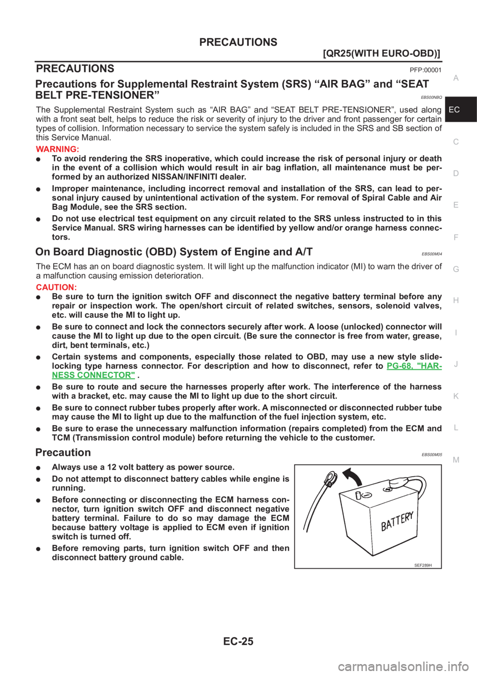
●Always use a 12 volt battery as power source.
●Do not attempt to disconnect battery cables while engine is
running.
●Before connecting or disconnecting the ECM harness con-
nector, turn ignition switch OFF and disconnect negative
battery terminal. Failure to do so may damage the ECM
because battery voltage is applied to ECM even if ignition
switch is turned off.
●Before removing parts, turn ignition switch OFF and then
disconnect battery ground cable.
SEF289H
Page 378 of 3833
EC-28
[QR25(WITH EURO-OBD)]
PRECAUTIONS
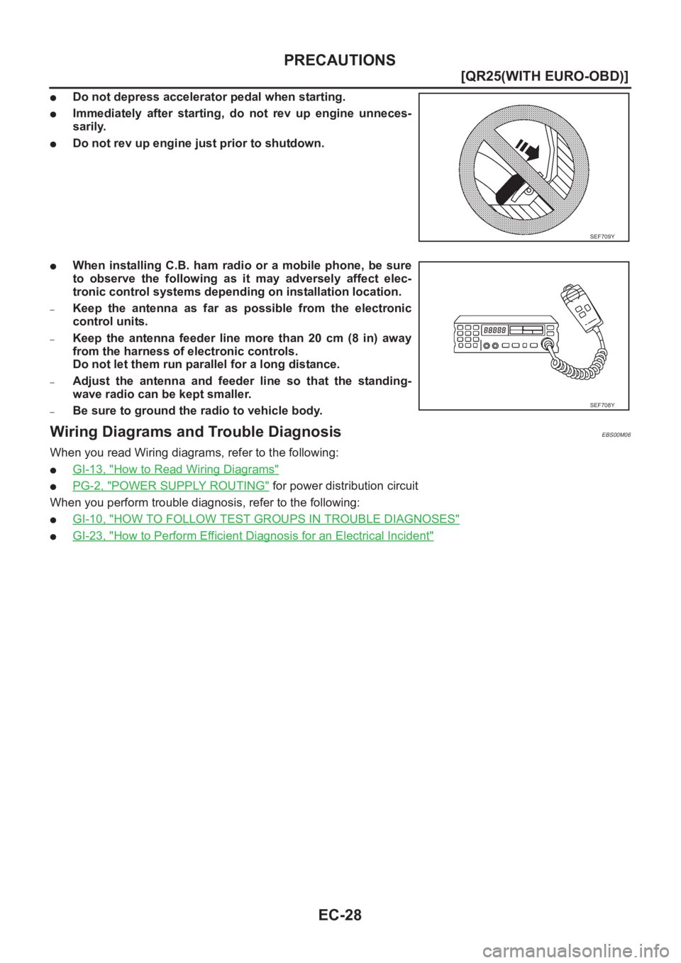
●Do not depress accelerator pedal when starting.
●Immediately after starting, do not rev up engine unneces-
sarily.
●Do not rev up engine just prior to shutdown.
●When installing C.B. ham radio or a mobile phone, be sure
to observe the following as it may adversely affect elec-
tronic control systems depending on installation location.
–Keep the antenna as far as possible from the electronic
control units.
–Keep the antenna feeder line more than 20 cm (8 in) away
from the harness of electronic controls.
Do not let them run parallel for a long distance.
–Adjust the antenna and feeder line so that the standing-
wave radio can be kept smaller.
–Be sure to ground the radio to vehicle body.
Wiring Diagrams and Trouble DiagnosisEBS00M06
When you read Wiring diagrams, refer to the following:
●GI-13, "How to Read Wiring Diagrams"
●PG-2, "POWER SUPPLY ROUTING" for power distribution circuit
When you perform trouble diagnosis, refer to the following:
●GI-10, "HOW TO FOLLOW TEST GROUPS IN TROUBLE DIAGNOSES"
●GI-23, "How to Perform Efficient Diagnosis for an Electrical Incident"
SEF709Y
SEF708Y
Page 387 of 3833
ENGINE CONTROL SYSTEM
EC-37
[QR25(WITH EURO-OBD)]
C
D
E
F
G
H
I
J
K
L
MA
EC
Fuel Cut Control (at No Load and High Engine Speed)EBS00M0F
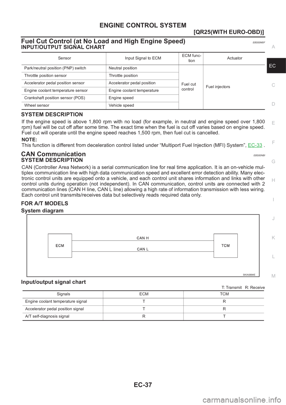
INPUT/OUTPUT SIGNAL CHART
SYSTEM DESCRIPTION
If the engine speed is above 1,800 rpm with no load (for example, in neutral and engine speed over 1,800
rpm) fuel will be cut off after some time. The exact time when the fuel is cut off varies based on engine speed.
Fuel cut will operate until the engine speed reaches 1,500 rpm, then fuel cut is cancelled.
NOTE:
This function is different from deceleration control listed under “Multiport Fuel Injection (MFI) System”, EC-33
.
CAN CommunicationEBS00NBI
SYSTEM DESCRIPTION
CAN (Controller Area Network) is a serial communication line for real time application. It is an on-vehicle mul-
tiplex communication line with high data communication speed and excellent error detection ability. Many elec-
tronic control units are equipped onto a vehicle, and each control unit shares information and links with other
control units during operation (not independent). In CAN communication, control units are connected with 2
communication lines (CAN H line, CAN L line) allowing a high rate of information transmission with less wiring.
Each control unit transmits/receives data but selectively reads required data only.
FOR A/T MODELS
System diagram
Input/output signal chart
T: Transmit R: Receive Sensor Input Signal to ECMECM func-
tionActuator
Park/neutral position (PNP) switch Neutral position
Fuel cut
controlFuel injectors Throttle position sensor Throttle position
Accelerator pedal position sensor Accelerator pedal position
Engine coolant temperature sensor Engine coolant temperature
Crankshaft position sensor (POS) Engine speed
Wheel sensor Vehicle speed
SKIA0884E
Signals ECM TCM
Engine coolant temperature signal T R
Accelerator pedal position signal T R
A/T self-diagnosis signal R T
Page 417 of 3833
TROUBLE DIAGNOSIS
EC-67
[QR25(WITH EURO-OBD)]
C
D
E
F
G
H
I
J
K
L
MA
EC
TROUBLE DIAGNOSISPFP:00004
Trouble Diagnosis IntroductionEBS00M0S
INTRODUCTION
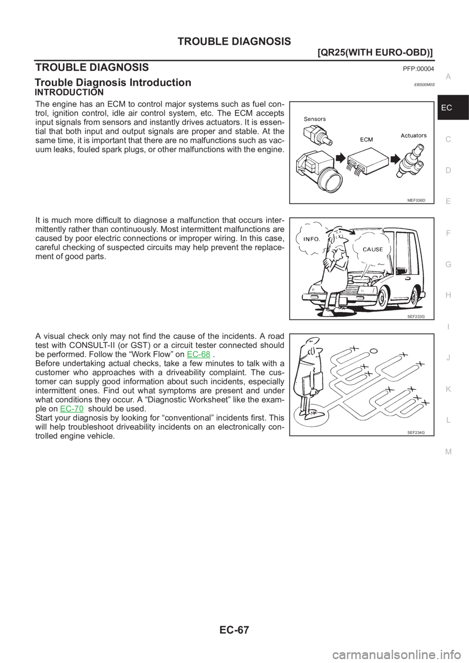
The engine has an ECM to control major systems such as fuel con-
trol, ignition control, idle air control system, etc. The ECM accepts
input signals from sensors and instantly drives actuators. It is essen-
tial that both input and output signals are proper and stable. At the
same time, it is important that there are no malfunctions such as vac-
uum leaks, fouled spark plugs, or other malfunctions with the engine.
It is much more difficult to diagnose a malfunction that occurs inter-
mittently rather than continuously. Most intermittent malfunctions are
caused by poor electric connections or improper wiring. In this case,
careful checking of suspected circuits may help prevent the replace-
ment of good parts.
A visual check only may not find the cause of the incidents. A road
test with CONSULT-II (or GST) or a circuit tester connected should
be performed. Follow the “Work Flow” on EC-68
.
Before undertaking actual checks, take a few minutes to talk with a
customer who approaches with a driveability complaint. The cus-
tomer can supply good information about such incidents, especially
intermittent ones. Find out what symptoms are present and under
what conditions they occur. A “Diagnostic Worksheet” like the exam-
ple on EC-70
should be used.
Start your diagnosis by looking for “conventional” incidents first. This
will help troubleshoot driveability incidents on an electronically con-
trolled engine vehicle.
MEF036D
SEF233G
SEF234G
Page 419 of 3833
TROUBLE DIAGNOSIS
EC-69
[QR25(WITH EURO-OBD)]
C
D
E
F
G
H
I
J
K
L
MA
EC
Description for Work Flow
DIAGNOSTIC WORKSHEET
Description
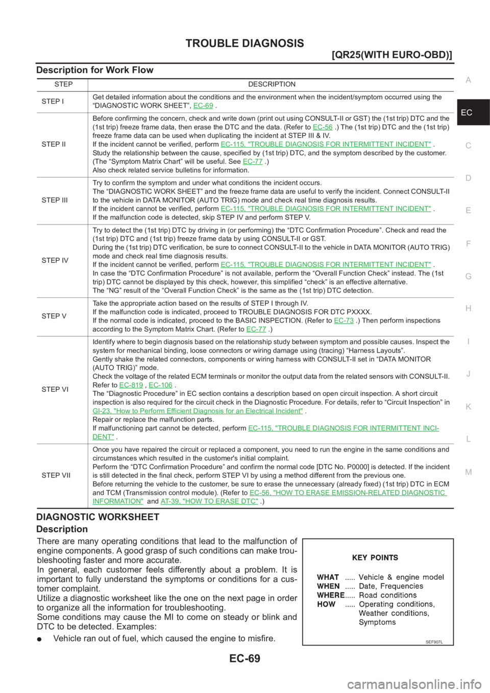
There are many operating conditions that lead to the malfunction of
engine components. A good grasp of such conditions can make trou-
bleshooting faster and more accurate.
In general, each customer feels differently about a problem. It is
important to fully understand the symptoms or conditions for a cus-
tomer complaint.
Utilize a diagnostic worksheet like the one on the next page in order
to organize all the information for troubleshooting.
Some conditions may cause the MI to come on steady or blink and
DTC to be detected. Examples:
●Vehicle ran out of fuel, which caused the engine to misfire.
STEP DESCRIPTION
STEP IGet detailed information about the conditions and the environment when the incident/symptom occurred using the
“DIAGNOSTIC WORK SHEET”, EC-69
.
STEP IIBefore confirming the concern, check and write down (print out using CONSULT-II or GST) the (1st trip) DTC and the
(1st trip) freeze frame data, then erase the DTC and the data. (Refer to EC-56
.) The (1st trip) DTC and the (1st trip)
freeze frame data can be used when duplicating the incident at STEP III & IV.
If the incident cannot be verified, perform EC-115, "
TROUBLE DIAGNOSIS FOR INTERMITTENT INCIDENT" .
Study the relationship between the cause, specified by (1st trip) DTC, and the symptom described by the customer.
(The “Symptom Matrix Chart” will be useful. See EC-77
.)
Also check related service bulletins for information.
STEP IIITry to confirm the symptom and under what conditions the incident occurs.
The “DIAGNOSTIC WORK SHEET” and the freeze frame data are useful to verify the incident. Connect CONSULT-II
to the vehicle in DATA MONITOR (AUTO TRIG) mode and check real time diagnosis results.
If the incident cannot be verified, perform EC-115, "
TROUBLE DIAGNOSIS FOR INTERMITTENT INCIDENT" .
If the malfunction code is detected, skip STEP IV and perform STEP V.
STEP IVTry to detect the (1st trip) DTC by driving in (or performing) the “DTC Confirmation Procedure”. Check and read the
(1st trip) DTC and (1st trip) freeze frame data by using CONSULT-II or GST.
During the (1st trip) DTC verification, be sure to connect CONSULT-II to the vehicle in DATA MONITOR (AUTO TRIG)
mode and check real time diagnosis results.
If the incident cannot be verified, perform EC-115, "
TROUBLE DIAGNOSIS FOR INTERMITTENT INCIDENT" .
In case the “DTC Confirmation Procedure” is not available, perform the “Overall Function Check” instead. The (1st
trip) DTC cannot be displayed by this check, however, this simplified “check” is an effective alternative.
The “NG” result of the “Overall Function Check” is the same as the (1st trip) DTC detection.
STEP VTake the appropriate action based on the results of STEP I through IV.
If the malfunction code is indicated, proceed to TROUBLE DIAGNOSIS FOR DTC PXXXX.
If the normal code is indicated, proceed to the BASIC INSPECTION. (Refer to EC-73
.) Then perform inspections
according to the Symptom Matrix Chart. (Refer to EC-77
.)
STEP VIIdentify where to begin diagnosis based on the relationship study between symptom and possible causes. Inspect the
system for mechanical binding, loose connectors or wiring damage using (tracing) “Harness Layouts”.
Gently shake the related connectors, components or wiring harness with CONSULT-II set in “DATA MONITOR
(AUTO TRIG)” mode.
Check the voltage of the related ECM terminals or monitor the output data from the related sensors with CONSULT-II.
Refer to EC-819
, EC-106 .
The “Diagnostic Procedure” in EC section contains a description based on open circuit inspection. A short circuit
inspection is also required for the circuit check in the Diagnostic Procedure. For details, refer to “Circuit Inspection” in
GI-23, "
How to Perform Efficient Diagnosis for an Electrical Incident" .
Repair or replace the malfunction parts.
If malfunctioning part cannot be detected, perform EC-115, "
TROUBLE DIAGNOSIS FOR INTERMITTENT INCI-
DENT" .
STEP VIIOnce you have repaired the circuit or replaced a component, you need to run the engine in the same conditions and
circumstances which resulted in the customer's initial complaint.
Perform the “DTC Confirmation Procedure” and confirm the normal code [DTC No. P0000] is detected. If the incident
is still detected in the final check, perform STEP VI by using a method different from the previous one.
Before returning the vehicle to the customer, be sure to erase the unnecessary (already fixed) (1st trip) DTC in ECM
and TCM (Transmission control module). (Refer to EC-56, "
HOW TO ERASE EMISSION-RELATED DIAGNOSTIC
INFORMATION" and AT-39, "HOW TO ERASE DTC" .)
SEF907L