wiring NISSAN X-TRAIL 2001 Service Service Manual
[x] Cancel search | Manufacturer: NISSAN, Model Year: 2001, Model line: X-TRAIL, Model: NISSAN X-TRAIL 2001Pages: 3833, PDF Size: 39.49 MB
Page 423 of 3833
TROUBLE DIAGNOSIS
EC-73
[QR25(WITH EURO-OBD)]
C
D
E
F
G
H
I
J
K
L
MA
EC
Basic InspectionEBS00M0V
1.INSPECTION START
1. Check service records for any recent repairs that may indicate a related incident, or a current need for
scheduled maintenance.
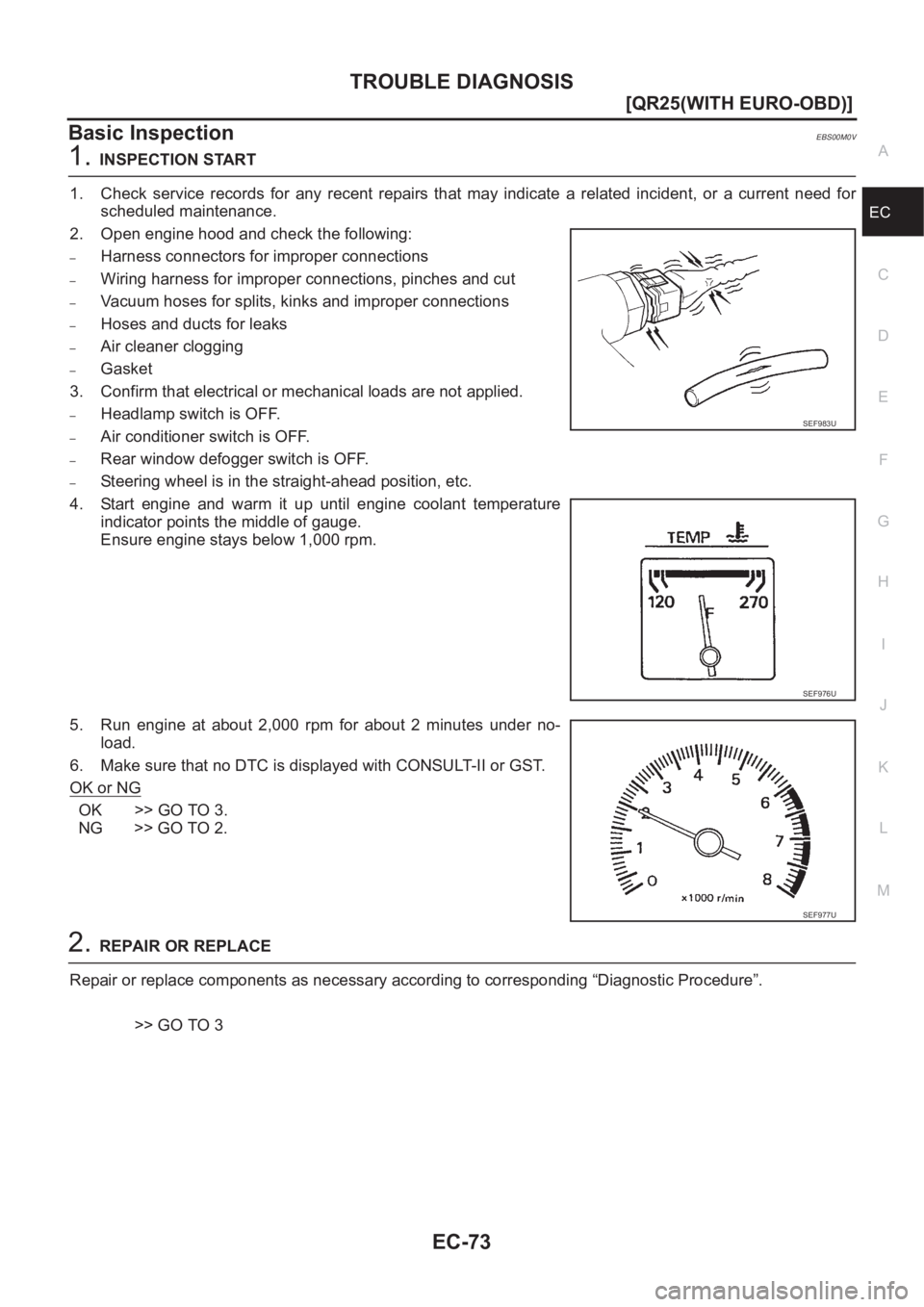
2. Open engine hood and check the following:
–Harness connectors for improper connections
–Wiring harness for improper connections, pinches and cut
–Vacuum hoses for splits, kinks and improper connections
–Hoses and ducts for leaks
–Air cleaner clogging
–Gasket
3. Confirm that electrical or mechanical loads are not applied.
–Headlamp switch is OFF.
–Air conditioner switch is OFF.
–Rear window defogger switch is OFF.
–Steering wheel is in the straight-ahead position, etc.
4. Start engine and warm it up until engine coolant temperature
indicator points the middle of gauge.
Ensure engine stays below 1,000 rpm.
5. Run engine at about 2,000 rpm for about 2 minutes under no-
load.
6. Make sure that no DTC is displayed with CONSULT-II or GST.
OK or NG
OK >> GO TO 3.
NG >> GO TO 2.
2.REPAIR OR REPLACE
Repair or replace components as necessary according to corresponding “Diagnostic Procedure”.
>> GO TO 3
SEF983U
SEF976U
SEF977U
Page 466 of 3833
EC-116
[QR25(WITH EURO-OBD)]
POWER SUPPLY CIRCUIT FOR ECM
POWER SUPPLY CIRCUIT FOR ECM
PFP:24110
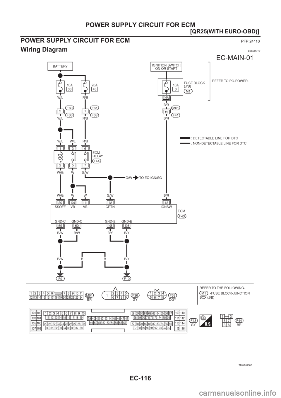
Wiring DiagramEBS00M1B
TBWA0136E
Page 468 of 3833
EC-118
[QR25(WITH EURO-OBD)]
POWER SUPPLY CIRCUIT FOR ECM
3. DETECT MALFUNCTIONING PART
Check the following.
●Harness connectors M61, F41
●Fuse block (J/B) connector M1
●10A fuse
●Harness for open or short between ECM and fuse
>> Repair harness or connectors.
4. CHECK ECM GROUND CIRCUIT FOR OPEN AND SHORT-I
1. Turn ignition switch “OFF”.
2. Disconnect ECM harness connector.
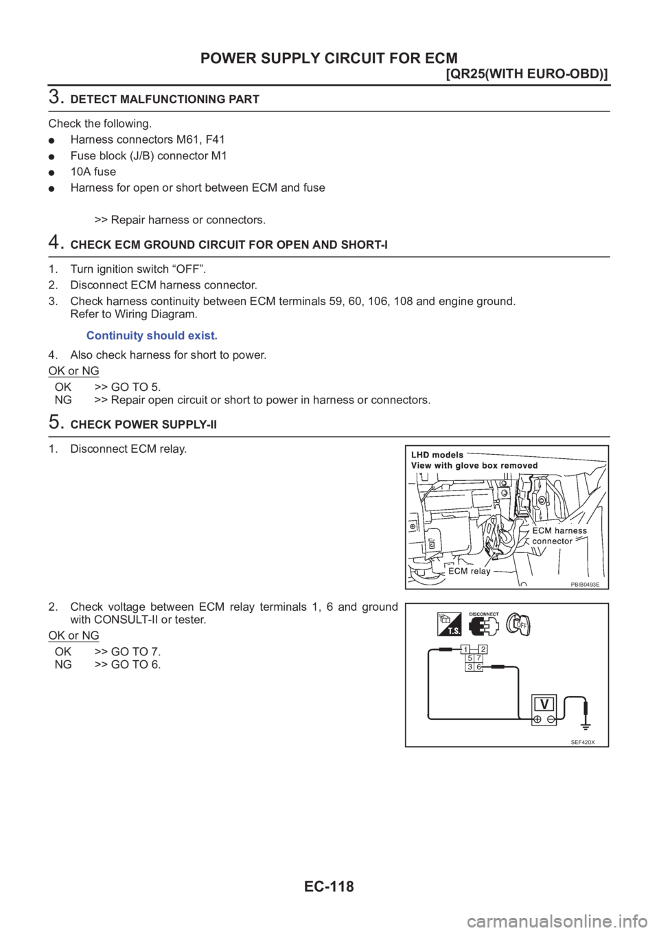
3. Check harness continuity between ECM terminals 59, 60, 106, 108 and engine ground.
Refer to Wiring Diagram.
4. Also check harness for short to power.
OK or NG
OK >> GO TO 5.
NG >> Repair open circuit or short to power in harness or connectors.
5. CHECK POWER SUPPLY-II
1. Disconnect ECM relay.
2. Check voltage between ECM relay terminals 1, 6 and ground
with CONSULT-II or tester.
OK or NG
OK >> GO TO 7.
NG >> GO TO 6.Continuity should exist.
PBIB0493E
SEF420X
Page 469 of 3833
POWER SUPPLY CIRCUIT FOR ECM
EC-119
[QR25(WITH EURO-OBD)]
C
D
E
F
G
H
I
J
K
L
MA
EC
6.DETECT MALFUNCTIONING PART
Check the following.
●10A fuse
●20A fuse
●Harness connectors E60, F36
●Harness connectors E61, F38
●Harness for open or short between ECM relay and battery
>> Repair open circuit or short to ground or short to power in harness or connectors.
7.CHECK OUTPUT SIGNAL CIRCUIT FOR OPEN AND SHORT
1. Check harness continuity between ECM terminal 20 and ECM relay terminal 2.
Refer to Wiring Diagram.
2. Also check harness for short to ground and short to power.
OK or NG
OK >> Go to EC-379, "IGNITION SIGNAL" .
NG >> Repair open circuit or short to ground or short to power in harness or connectors.
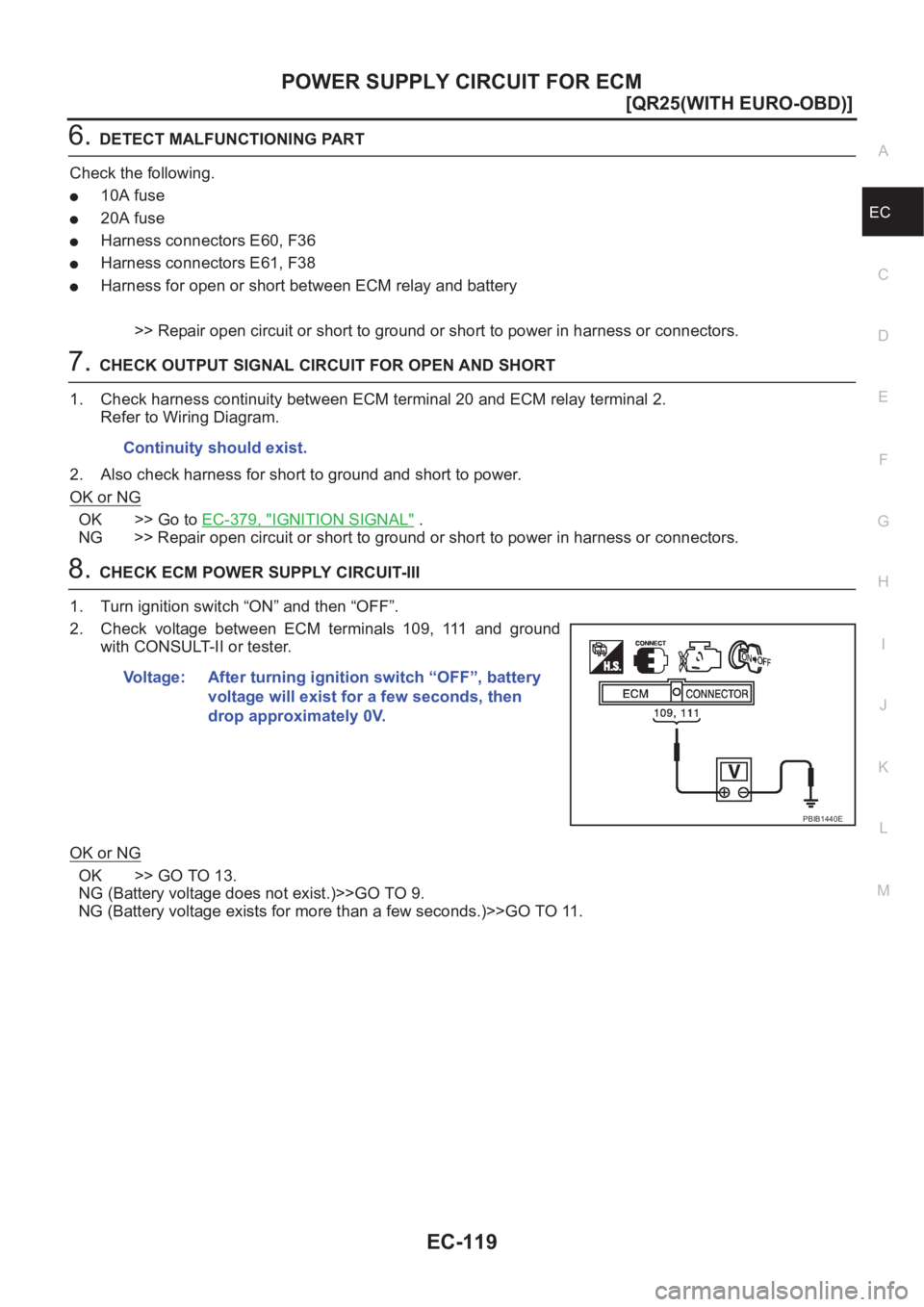
8.CHECK ECM POWER SUPPLY CIRCUIT-III
1. Turn ignition switch “ON” and then “OFF”.
2. Check voltage between ECM terminals 109, 111 and ground
with CONSULT-II or tester.
OK or NG
OK >> GO TO 13.
NG (Battery voltage does not exist.)>>GO TO 9.
NG (Battery voltage exists for more than a few seconds.)>>GO TO 11. Continuity should exist.
Voltage: After turning ignition switch “OFF”, battery
voltage will exist for a few seconds, then
drop approximately 0V.
PBIB1440E
Page 470 of 3833
EC-120
[QR25(WITH EURO-OBD)]
POWER SUPPLY CIRCUIT FOR ECM
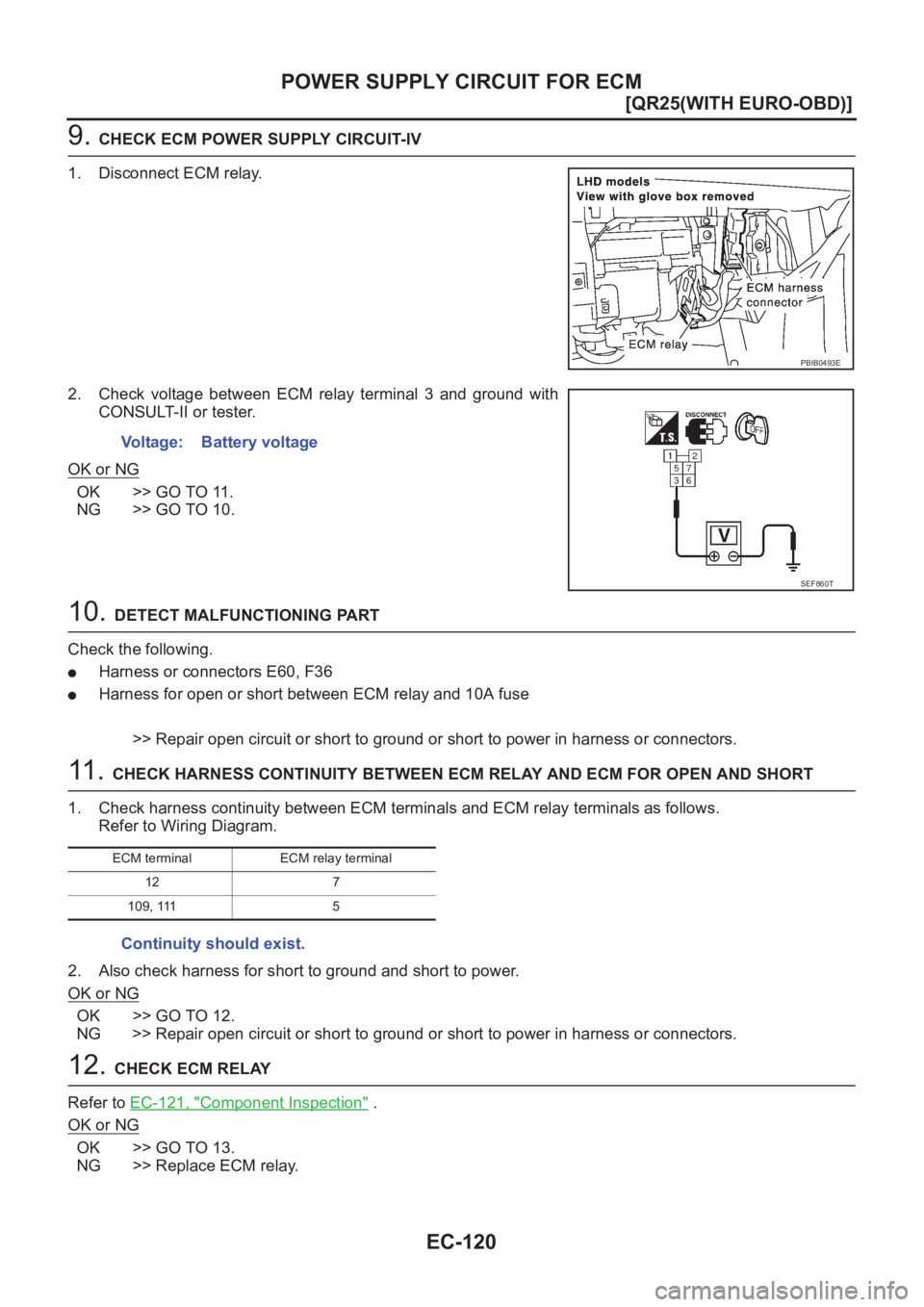
9. CHECK ECM POWER SUPPLY CIRCUIT-IV
1. Disconnect ECM relay.
2. Check voltage between ECM relay terminal 3 and ground with
CONSULT-II or tester.
OK or NG
OK >> GO TO 11.
NG >> GO TO 10.
10. DETECT MALFUNCTIONING PART
Check the following.
●Harness or connectors E60, F36
●Harness for open or short between ECM relay and 10A fuse
>> Repair open circuit or short to ground or short to power in harness or connectors.
11 . CHECK HARNESS CONTINUITY BETWEEN ECM RELAY AND ECM FOR OPEN AND SHORT
1. Check harness continuity between ECM terminals and ECM relay terminals as follows.
Refer to Wiring Diagram.
2. Also check harness for short to ground and short to power.
OK or NG
OK >> GO TO 12.
NG >> Repair open circuit or short to ground or short to power in harness or connectors.
12. CHECK ECM RELAY
Refer to EC-121, "
Component Inspection" .
OK or NG
OK >> GO TO 13.
NG >> Replace ECM relay.
PBIB0493E
Voltage: Battery voltage
SEF860T
ECM terminal ECM relay terminal
12 7
109, 111 5
Continuity should exist.
Page 471 of 3833
POWER SUPPLY CIRCUIT FOR ECM
EC-121
[QR25(WITH EURO-OBD)]
C
D
E
F
G
H
I
J
K
L
MA
EC
13.CHECK ECM GROUND CIRCUIT FOR OPEN AND SHORT-II
1. Turn ignition switch “OFF”.
2. Disconnect ECM harness connector.
3. Check harness continuity between ECM terminals 59, 60, 106, 108 and engine ground.
Refer to Wiring Diagram.
4. Also check harness for short to power.
OK or NG
OK >> GO TO 14.
NG >> Repair open circuit or short to power in harness or connectors.
14.CHECK INTERMITTENT INCIDENT
Refer to EC-115, "
TROUBLE DIAGNOSIS FOR INTERMITTENT INCIDENT" .
>>INSPECTION END
Component InspectionEBS00M1E
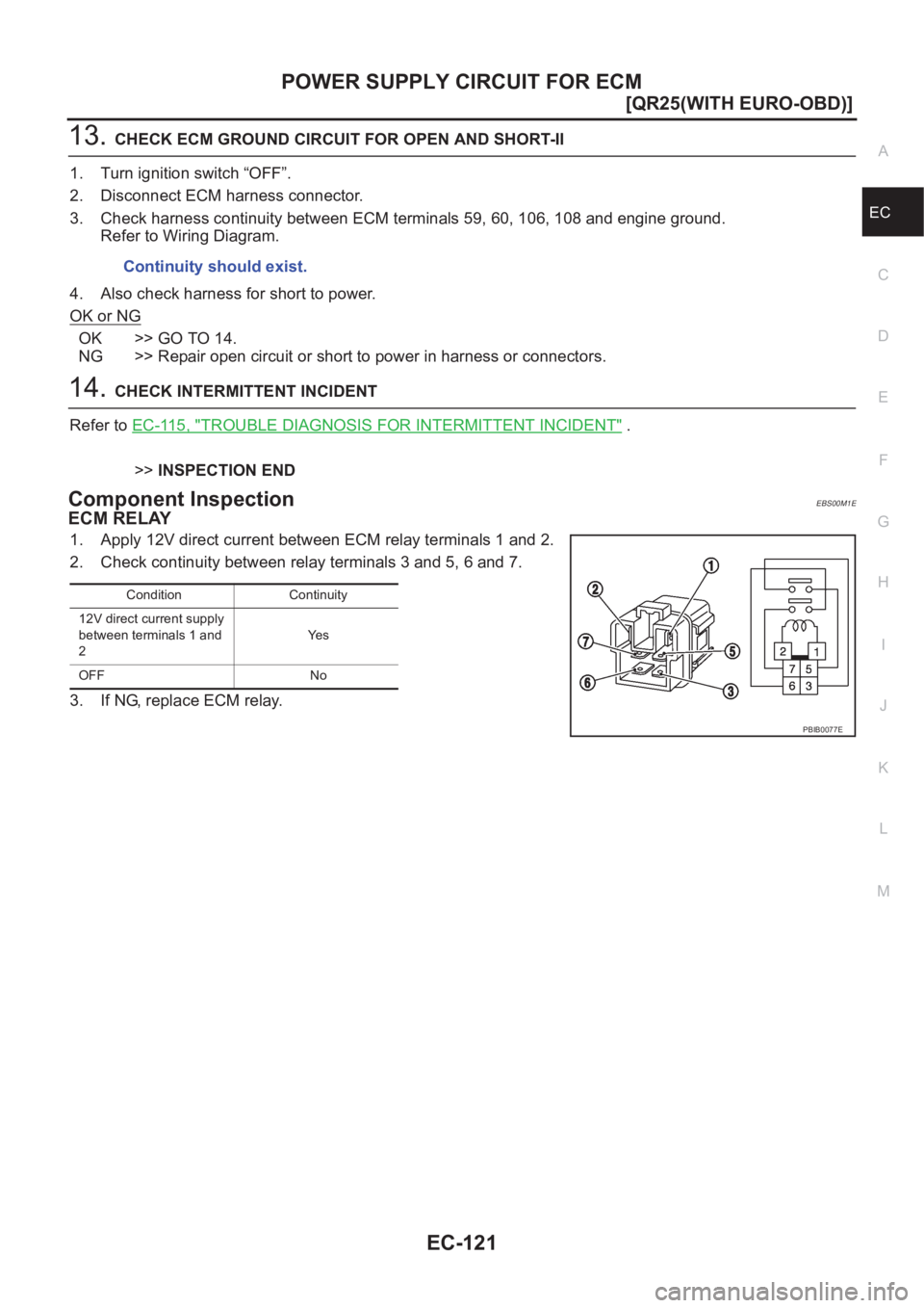
ECM RELAY
1. Apply 12V direct current between ECM relay terminals 1 and 2.
2. Check continuity between relay terminals 3 and 5, 6 and 7.
3. If NG, replace ECM relay.Continuity should exist.
Condition Continuity
12V direct current supply
between terminals 1 and
2Ye s
OFF No
PBIB0077E
Page 472 of 3833
EC-122
[QR25(WITH EURO-OBD)]
DTC U1000 CAN COMMUNICATION LINE
DTC U1000 CAN COMMUNICATION LINE
PFP:23710
DescriptionEBS00M1F
CAN (Controller Area Network) is a serial communication line for real time application. It is an on-vehicle mul-
tiplex communication line with high data communication speed and excellent error detection ability. Many elec-
tric control units are equipped onto a vehicle, and each control unit shares information and links with other
control units during operation (not independent). In CAN communication, control units are connected with 2
communication lines (CAN H line, CAN L line) allowing a high rate of information transmission with less wiring.
Each control unit transmits/receives data but selectively reads required data only.
On Board Diagnosis LogicEBS00M1G
This self-diagnosis has the one trip detection logic.
DTC Confirmation ProcedureEBS00M1H
1. Turn ignition switch “ON” and wait at least 3 seconds.
2. Select “DATA MONITOR” mode with CONSULT-II.
3. If 1st trip DTC is detected, go to EC-124, "
Diagnostic Procedure" .
DTC No.Trouble diagnosis
nameDTC detecting condition Possible cause
U1000
1000CAN communication
line
●ECM can not communicate to other control
units.
●ECM can not communicate for more than the
specified time.
●Harness or connectors
(CAN communication line is open or
shorted)
Page 473 of 3833
DTC U1000 CAN COMMUNICATION LINE
EC-123
[QR25(WITH EURO-OBD)]
C
D
E
F
G
H
I
J
K
L
MA
EC
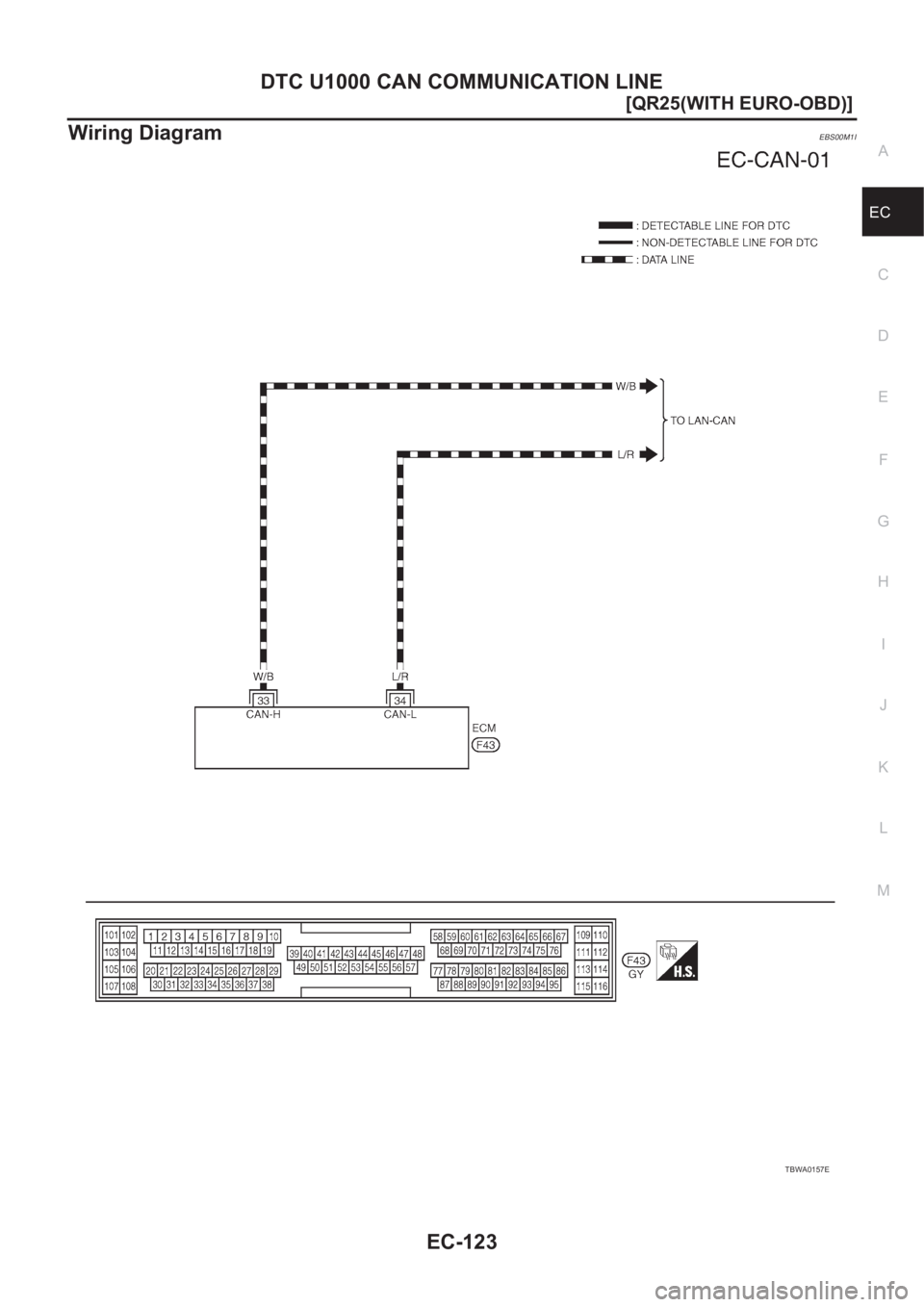
Wiring DiagramEBS00M1I
TBWA0157E
Page 477 of 3833
DTC P0011 IVT CONTROL
EC-127
[QR25(WITH EURO-OBD)]
C
D
E
F
G
H
I
J
K
L
MA
EC
4. If 1st trip DTC is detected, go to EC-127, "Diagnostic Procedure" .
WITH GST
Follow the procedure “With CONSULT-II” above.
Diagnostic ProcedureEBS00M1P
1.CHECK CRANKSHAFT POSITION SENSOR (POS)
Refer to EC-231, "
Component Inspection" .
OK or NG
OK >> GO TO 2.
NG >> Replace crankshaft position sensor (POS).
2.CHECK CAMSHAFT POSITION SENSOR (PHASE)
Refer to EC-238, "
Component Inspection" .
OK or NG
OK >> GO TO 3.
NG >> Replace camshaft position sensor (PHASE).
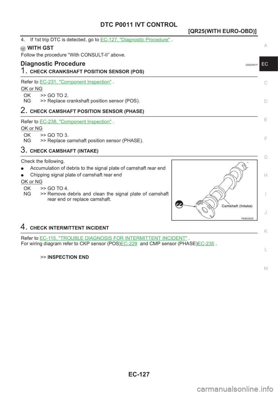
3.CHECK CAMSHAFT (INTAKE)
Check the following.
●Accumulation of debris to the signal plate of camshaft rear end
●Chipping signal plate of camshaft rear end
OK or NG
OK >> GO TO 4.
NG >> Remove debris and clean the signal plate of camshaft
rear end or replace camshaft.
4.CHECK INTERMITTENT INCIDENT
Refer to EC-115, "
TROUBLE DIAGNOSIS FOR INTERMITTENT INCIDENT" .
For wiring diagram refer to CKP sensor (POS)EC-229
and CMP sensor (PHASE)EC-235 .
>>INSPECTION END
PBIB0565E
Page 480 of 3833
EC-130
[QR25(WITH EURO-OBD)]
DTC P0031, P0032 HO2S1 HEATER
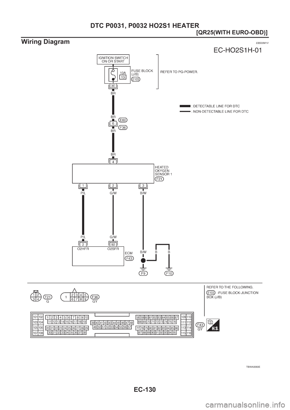
Wiring Diagram
EBS00M1V
TBWA0060E