valve yd22 NISSAN X-TRAIL 2001 Service Repair Manual
[x] Cancel search | Manufacturer: NISSAN, Model Year: 2001, Model line: X-TRAIL, Model: NISSAN X-TRAIL 2001Pages: 3833, PDF Size: 39.49 MB
Page 52 of 3833

EM-2
TIMING CHAIN .......................................................... 37
Removal and Installation ........................................ 37
REMOVAL ........................................................... 38
INSPECTION AFTER REMOVAL ........................ 41
INSTALLATION .................................................... 41
CAMSHAFT ............................................................... 46
Removal and Installation ........................................ 46
REMOVAL ........................................................... 46
INSTALLATION .................................................... 48
INSPECTION AFTER REMOVAL ........................ 51
Valve Clearance ...................................................... 53
INSPECTION ....................................................... 53
ADJUSTMENT .................................................... 54
OIL SEAL .................................................................. 56
Removal and Installation of Valve Oil Seal ............. 56
REMOVAL ........................................................... 56
INSTALLATION .................................................... 56
Removal and Installation of Front Oil Seal ............. 56
REMOVAL ........................................................... 56
INSTALLATION .................................................... 57
Removal and Installation of Rear Oil Seal .............. 57
REMOVAL ........................................................... 57
INSTALLATION .................................................... 57
CYLINDER HEAD .................................................. ... 59
On-Vehicle Service ................................................. 59
CHECKING COMPRESSION PRESSURE ......... 59
Removal and Installation ........................................ 60
REMOVAL ........................................................... 60
INSPECTION AFTER REMOVAL ........................ 61
INSTALLATION .................................................... 61
Disassembly and Assembly .................................... 62
DISASSEMBLY ................................................... 63
ASSEMBLY ......................................................... 63
Inspection After Disassembly ................................. 64
CYLINDER HEAD DISTORTION ........................ 64
VALVE DIMENSIONS .......................................... 64
VALVE GUIDE CLEARANCE .............................. 65
VALVE GUIDE REPLACEMENT ......................... 65
VALVE SEAT CONTACT ..................................... 66
VALVE SEAT REPLACEMENT ........................... 66
VALVE SPRING SQUARENESS ......................... 67
VALVE SPRING DIMENSIONS AND VALVE
SPRING PRESSURE LOAD ............................... 68
ENGINE ASSEMBLY ................................................ 69
Removal and Installation ........................................ 69
REMOVAL .......................................................
.... 69
INSTALLATION .................................................... 71
INSPECTION AFTER INSTALLATION ................ 71
CYLINDER BLOCK ................................................... 73
Disassembly and Assembly .................................... 73
DISASSEMBLY ................................................... 74
ASSEMBLY ......................................................... 78
How to Select Piston and Bearing .......................... 82
DESCRIPTION .................................................... 82
HOW TO SELECT PISTON ................................. 83
HOW TO SELECT CONNECTING ROD BEAR-
ING ...................................................................... 83HOW TO SELECT MAIN BEARING .................... 85
Inspection After Disassembly .................................. 88
CRANKSHAFT END PLAY .................................. 88
CONNECTING ROD SIDE CLEARANCE ........... 89
PISTON AND PISTON PIN CLEARANCE ........... 89
PISTON RING SIDE CLEARANCE ..................... 90
PISTON RING END GAP .................................... 90
CONNECTING ROD BEND AND TORSION ....... 91
CONNECTING ROD BEARING (BIG END) ........ 91
CONNECTING ROD BUSHING OIL CLEAR-
ANCE (SMALL END) ........................................... 91
CYLINDER BLOCK DISTORTION ...................... 92
INNER DIAMETER OF MAIN BEARING HOUS-
ING ....................................................................... 93
PISTON TO CYLINDER BORE CLEARANCE .... 93
OUTER DIAMETER OF CRANKSHAFT JOUR-
NAL ...................................................................... 94
OUTER DIAMETER OF CRANKSHAFT PIN ...... 94
OUT-OF-ROUND AND TAPER OF CRANK-
SHAFT ................................................................. 94
CRANKSHAFT RUNOUT .................................... 95
CONNECTING ROD BEARING OIL CLEAR-
ANCE ................................................................... 95
MAIN BEARING OIL CLEARANCE ..................... 95
MAIN BEARING CRUSH HEIGHT ...................... 96
OUTER DIAMETER OF LOWER CYLINDER
BLOCK MOUNTING BOLT .................................. 96
OUTER DIAMETER OF CONNECTING ROD
BOLT .................................................................... 96
MOVEMENT AMOUNT OF FLYWHEEL (M/T
MODELS) ............................................................. 97
SERVICE DATA AND SPECIFICATIONS (SDS) ...... 98
Standard and Limit .................................................. 98
GENERAL SPECIFICATIONS ............................. 98
DRIVE BELTS ...................................................... 98
INTAKE MANIFOLD AND EXHAUST MANI-
FOLD ................................................................... 98
SPARK PLUG ...................................................... 98
CYLINDER HEAD ................................................ 98
VALVE .................................................................. 99
CAMSHAFT AND CAMSHAFT BEARING .........102
CYLINDER BLOCK ............................................102
PISTON, PISTON RING AND PISTON PIN .....
.103
CONNECTING ROD ..........................................104
CRANKSHAFT ...................................................105
MAIN BEARING .................................................106
CONNECTING ROD BEARING .........................107
Tightening Torque .................................................108
YD22DDTi
PRECAUTIONS .......................................................110
Precautions for Drain Engine Coolant ...................110
Precautions for Disconnecting Fuel Piping ...........110
Precautions for Removal and Disassembly ..........110
Precautions for Inspection, Repair and Replace-
ment ......................................................................110
Precautions for Assembly and Installation ............110
Page 162 of 3833
EM-112
[YD22DDTi]
PREPARATION
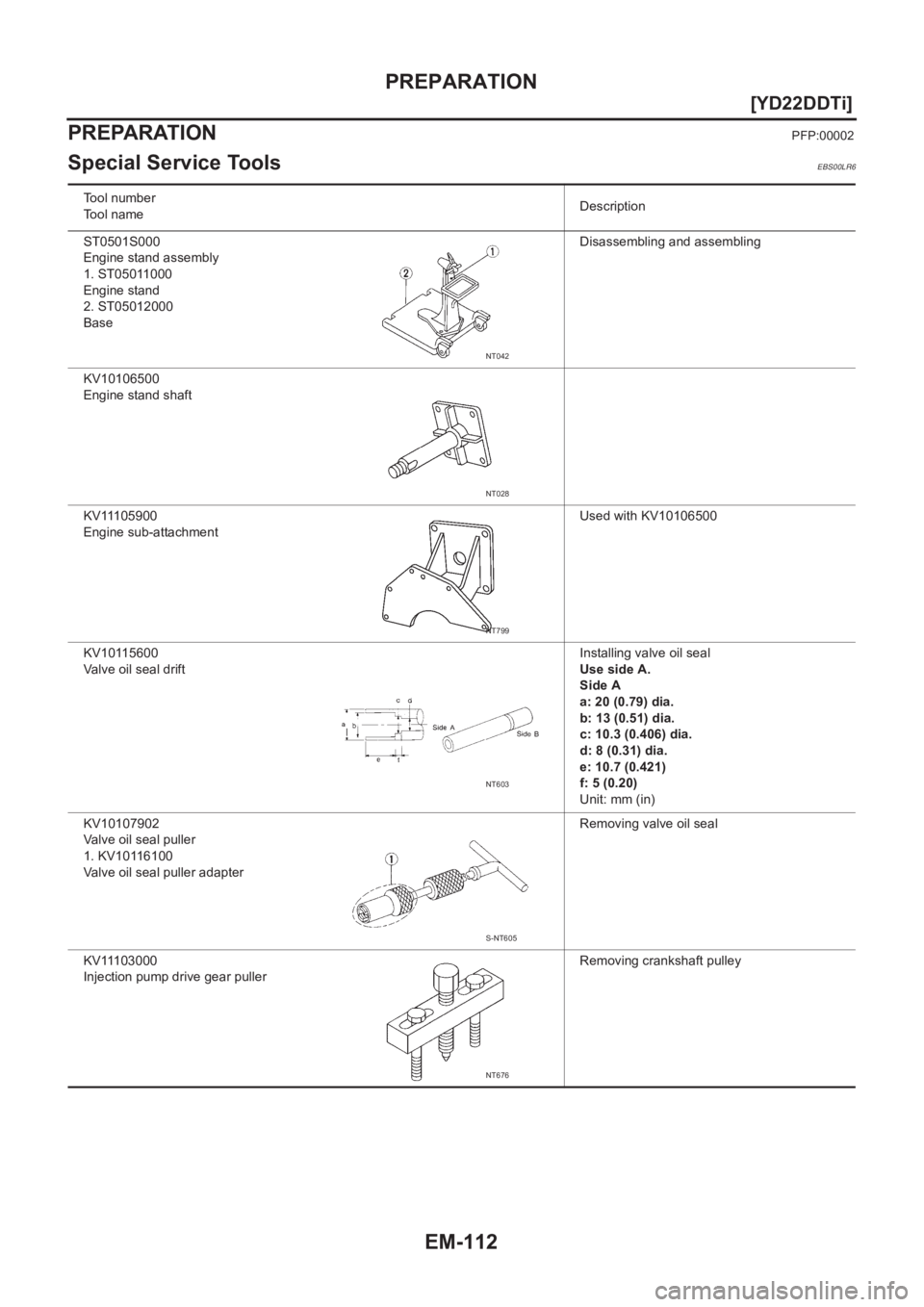
PREPARATION
PFP:00002
Special Service ToolsEBS00LR6
Tool number
Tool nameDescription
ST0501S000
Engine stand assembly
1. ST05011000
Engine stand
2. ST05012000
BaseDisassembling and assembling
KV10106500
Engine stand shaft
KV11105900
Engine sub-attachmentUsed with KV10106500
KV10115600
Valve oil seal driftInstalling valve oil seal
Use side A.
Side A
a: 20 (0.79) dia.
b: 13 (0.51) dia.
c: 10.3 (0.406) dia.
d: 8 (0.31) dia.
e: 10.7 (0.421)
f: 5 (0.20)
Unit: mm (in)
KV10107902
Valve oil seal puller
1. KV10116100
Valve oil seal puller adapterRemoving valve oil seal
KV11103000
Injection pump drive gear pullerRemoving crankshaft pulley
NT042
NT028
NT799
NT603
S-NT605
NT676
Page 163 of 3833
PREPARATION
EM-113
[YD22DDTi]
C
D
E
F
G
H
I
J
K
L
MA
EM
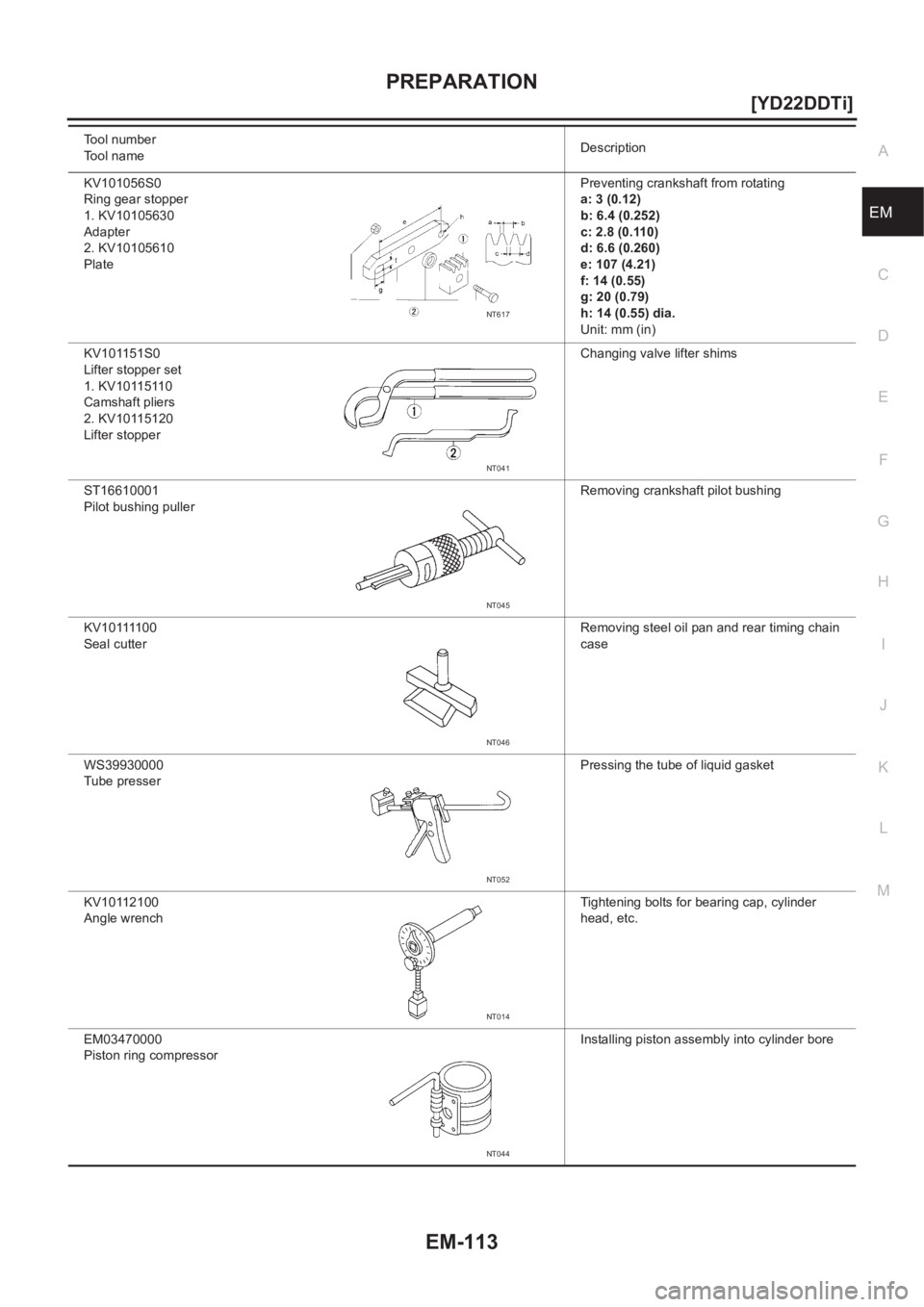
KV101056S0
Ring gear stopper
1. KV10105630
Adapter
2. KV10105610
PlatePreventing crankshaft from rotating
a: 3 (0.12)
b: 6.4 (0.252)
c: 2.8 (0.110)
d: 6.6 (0.260)
e: 107 (4.21)
f: 14 (0.55)
g: 20 (0.79)
h: 14 (0.55) dia.
Unit: mm (in)
KV101151S0
Lifter stopper set
1. KV10115110
Camshaft pliers
2. KV10115120
Lifter stopperChanging valve lifter shims
ST16610001
Pilot bushing pullerRemoving crankshaft pilot bushing
K V 1 0 1111 0 0
Seal cutterRemoving steel oil pan and rear timing chain
case
WS39930000
Tube presserPressing the tube of liquid gasket
KV10112100
Angle wrenchTightening bolts for bearing cap, cylinder
head, etc.
EM03470000
Piston ring compressorInstalling piston assembly into cylinder bore Tool number
To o l n a m eDescription
NT617
NT041
NT045
NT046
NT052
NT014
NT044
Page 165 of 3833
PREPARATION
EM-115
[YD22DDTi]
C
D
E
F
G
H
I
J
K
L
MA
EM
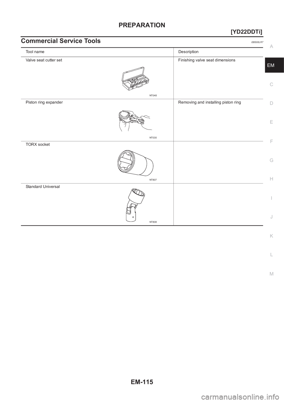
Commercial Service ToolsEBS00LR7
To o l n a m eDescription
Valve seat cutter set Finishing valve seat dimensions
Piston ring expander Removing and installing piston ring
TORX socket
Standard Universal
NT048
NT030
NT807
NT808
Page 167 of 3833
NOISE, VIBRATION, AND HARSHNESS (NVH) TROUBLESHOOTING
EM-117
[YD22DDTi]
C
D
E
F
G
H
I
J
K
L
MA
EM
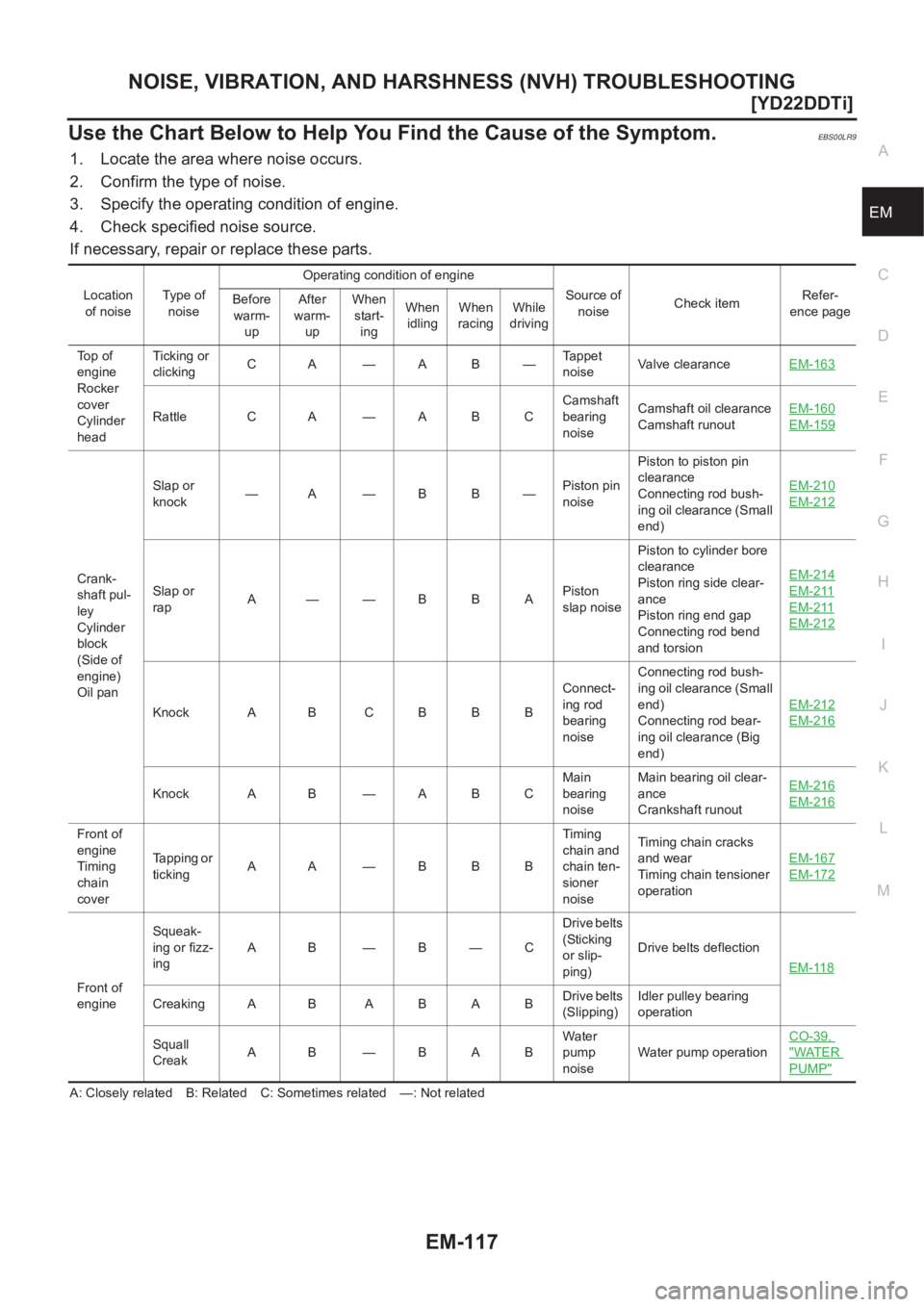
Use the Chart Below to Help You Find the Cause of the Symptom.EBS00LR9
1. Locate the area where noise occurs.
2. Confirm the type of noise.
3. Specify the operating condition of engine.
4. Check specified noise source.
If necessary, repair or replace these parts.
A: Closely related B: Related C: Sometimes related —: Not relatedLocation
of noiseType of
noiseOperating condition of engine
Source of
noiseCheck itemRefer-
ence page Before
warm-
upAfter
warm-
upWhen
start-
ingWhen
idlingWhen
racingWhile
driving
Top of
engine
Rocker
cover
Cylinder
headTicking or
clickingCA—AB—Tappet
noiseValve clearanceEM-163
Rattle C A — A B CCamshaft
bearing
noiseCamshaft oil clearance
Camshaft runoutEM-160EM-159
Crank-
shaft pul-
ley
Cylinder
block
(Side of
engine)
Oil panSlap or
knock—A—BB—Piston pin
noisePiston to piston pin
clearance
Connecting rod bush-
ing oil clearance (Small
end)EM-210
EM-212
Slap or
rapA ——BBAPiston
slap noisePiston to cylinder bore
clearance
Piston ring side clear-
ance
Piston ring end gap
Connecting rod bend
and torsionEM-214EM-211
EM-211
EM-212
Knock A B C B B BConnect-
ing rod
bearing
noiseConnecting rod bush-
ing oil clearance (Small
end)
Connecting rod bear-
ing oil clearance (Big
end)EM-212EM-216
Knock A B — A B CMain
bearing
noiseMain bearing oil clear-
ance
Crankshaft runoutEM-216EM-216
Front of
engine
Timing
chain
coverTapping or
tickingA A —BBBTiming
chain and
chain ten-
sioner
noiseTiming chain cracks
and wear
Timing chain tensioner
operationEM-167
EM-172
Front of
engineSqueak-
ing or fizz-
ingAB—B—CDrive belts
(Sticking
or slip-
ping)Drive belts deflection
EM-118
CreakingA B ABABDrive belts
(Slipping)Idler pulley bearing
operation
Squall
CreakA B —BABWater
pump
noiseWater pump operationCO-39,
"WATER
PUMP"
Page 173 of 3833
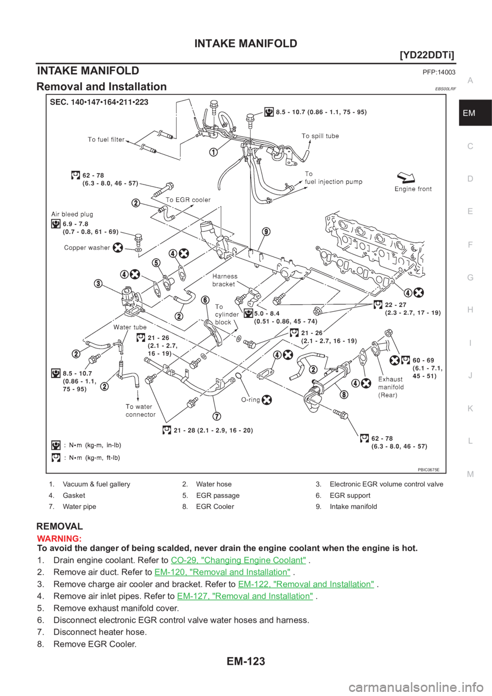
INTAKE MANIFOLD
EM-123
[YD22DDTi]
C
D
E
F
G
H
I
J
K
L
MA
EM
INTAKE MANIFOLDPFP:14003
Removal and InstallationEBS00LRF
REMOVAL
WARNING:
To avoid the danger of being scalded, never drain the engine coolant when the engine is hot.
1. Drain engine coolant. Refer to CO-29, "
Changing Engine Coolant" .
2. Remove air duct. Refer to EM-120, "
Removal and Installation" .
3. Remove charge air cooler and bracket. Refer to EM-122, "
Removal and Installation" .
4. Remove air inlet pipes. Refer to EM-127, "
Removal and Installation" .
5. Remove exhaust manifold cover.
6. Disconnect electronic EGR control valve water hoses and harness.
7. Disconnect heater hose.
8. Remove EGR Cooler.
PBIC0675E
1. Vacuum & fuel gallery 2. Water hose 3. Electronic EGR volume control valve
4. Gasket 5. EGR passage 6. EGR support
7. Water pipe 8. EGR Cooler 9. Intake manifold
Page 174 of 3833
EM-124
[YD22DDTi]
INTAKE MANIFOLD
9. Remove vacuum hose.
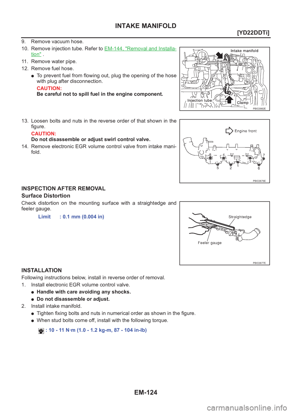
10. Remove injection tube. Refer to EM-144, "
Removal and Installa-
tion" .
11. Remove water pipe.
12. Remove fuel hose.
●To prevent fuel from flowing out, plug the opening of the hose
with plug after disconnection.
CAUTION:
Be careful not to spill fuel in the engine component.
13. Loosen bolts and nuts in the reverse order of that shown in the
figure.
CAUTION:
Do not disassemble or adjust swirl control valve.
14. Remove electronic EGR volume control valve from intake mani-
fold.
INSPECTION AFTER REMOVAL
Surface Distortion
Check distortion on the mounting surface with a straightedge and
feeler gauge.
INSTALLATION
Following instructions below, install in reverse order of removal.
1. Install electronic EGR volume control valve.
●Handle with care avoiding any shocks.
●Do not disassemble or adjust.
2. Install intake manifold.
●Tighten fixing bolts and nuts in numerical order as shown in the figure.
●When stud bolts come off, install with the following torque.
PBIC0982E
PBIC0676E
Limit : 0.1 mm (0.004 in)
PBIC0677E
: 10 - 11 N·m (1.0 - 1.2 kg-m, 87 - 104 in-lb)
Page 177 of 3833
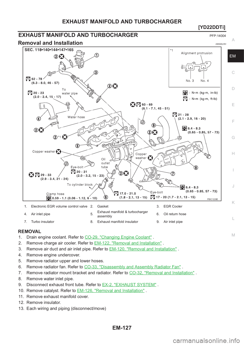
EXHAUST MANIFOLD AND TURBOCHARGER
EM-127
[YD22DDTi]
C
D
E
F
G
H
I
J
K
L
MA
EM
EXHAUST MANIFOLD AND TURBOCHARGERPFP:14004
Removal and InstallationEBS00LRH
REMOVAL
1. Drain engine coolant. Refer to CO-29, "Changing Engine Coolant" .
2. Remove charge air cooler. Refer to EM-122, "
Removal and Installation" .
3. Remove air duct and air inlet pipe. Refer to EM-120, "
Removal and Installation" .
4. Remove engine undercover.
5. Remove radiator upper and lower hoses.
6. Remove radiator fan. Refer to CO-33, "
Disassembly and Assembly Radiator Fan" .
7. Remove radiator mount bracket and radiator. Refer to CO-32, "
Removal and Installation" .
8. Remove water inlet pipe.
9. Disconnect exhaust front tube. Refer to EX-2, "
EXHAUST SYSTEM" .
10. Remove catalyst. Refer to EM-126, "
Removal and Installation" .
11. Remove exhaust manifold cover.
12. Remove insulator.
13. Each wiring and piping (disconnect/move)
PBIC1228E
1. Electronic EGR volume control valve 2. Gasket 3. EGR Cooler
4. Air inlet pipe 5.Exhaust manifold & turbocharger
assembly6. Oil return hose
7. Turbo insulator 8. Exhaust manifold insulator 9. Air inlet pipe
Page 181 of 3833
EXHAUST MANIFOLD AND TURBOCHARGER
EM-131
[YD22DDTi]
C
D
E
F
G
H
I
J
K
L
MA
EM
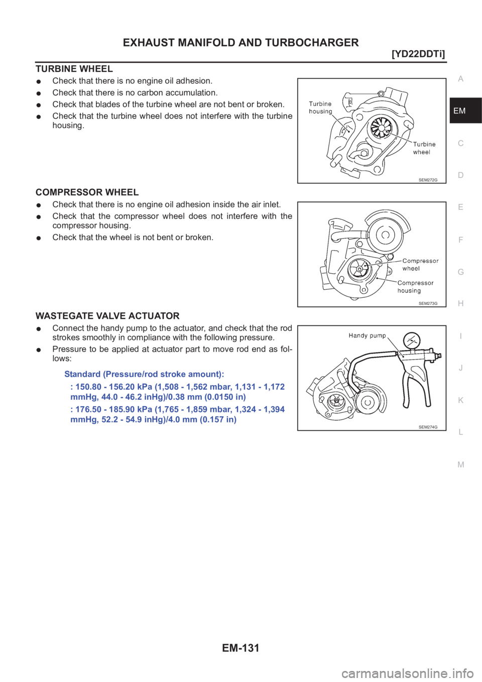
TURBINE WHEEL
●Check that there is no engine oil adhesion.
●Check that there is no carbon accumulation.
●Check that blades of the turbine wheel are not bent or broken.
●Check that the turbine wheel does not interfere with the turbine
housing.
COMPRESSOR WHEEL
●Check that there is no engine oil adhesion inside the air inlet.
●Check that the compressor wheel does not interfere with the
compressor housing.
●Check that the wheel is not bent or broken.
WASTEGATE VALVE ACTUATOR
●Connect the handy pump to the actuator, and check that the rod
strokes smoothly in compliance with the following pressure.
●Pressure to be applied at actuator part to move rod end as fol-
lows:
SEM272G
SEM273G
Standard (Pressure/rod stroke amount):
: 150.80 - 156.20 kPa (1,508 - 1,562 mbar, 1,131 - 1,172
mmHg, 44.0 - 46.2 inHg)/0.38 mm (0.0150 in)
: 176.50 - 185.90 kPa (1,765 - 1,859 mbar, 1,324 - 1,394
mmHg, 52.2 - 54.9 inHg)/4.0 mm (0.157 in)
SEM274G
Page 190 of 3833
EM-140
[YD22DDTi]
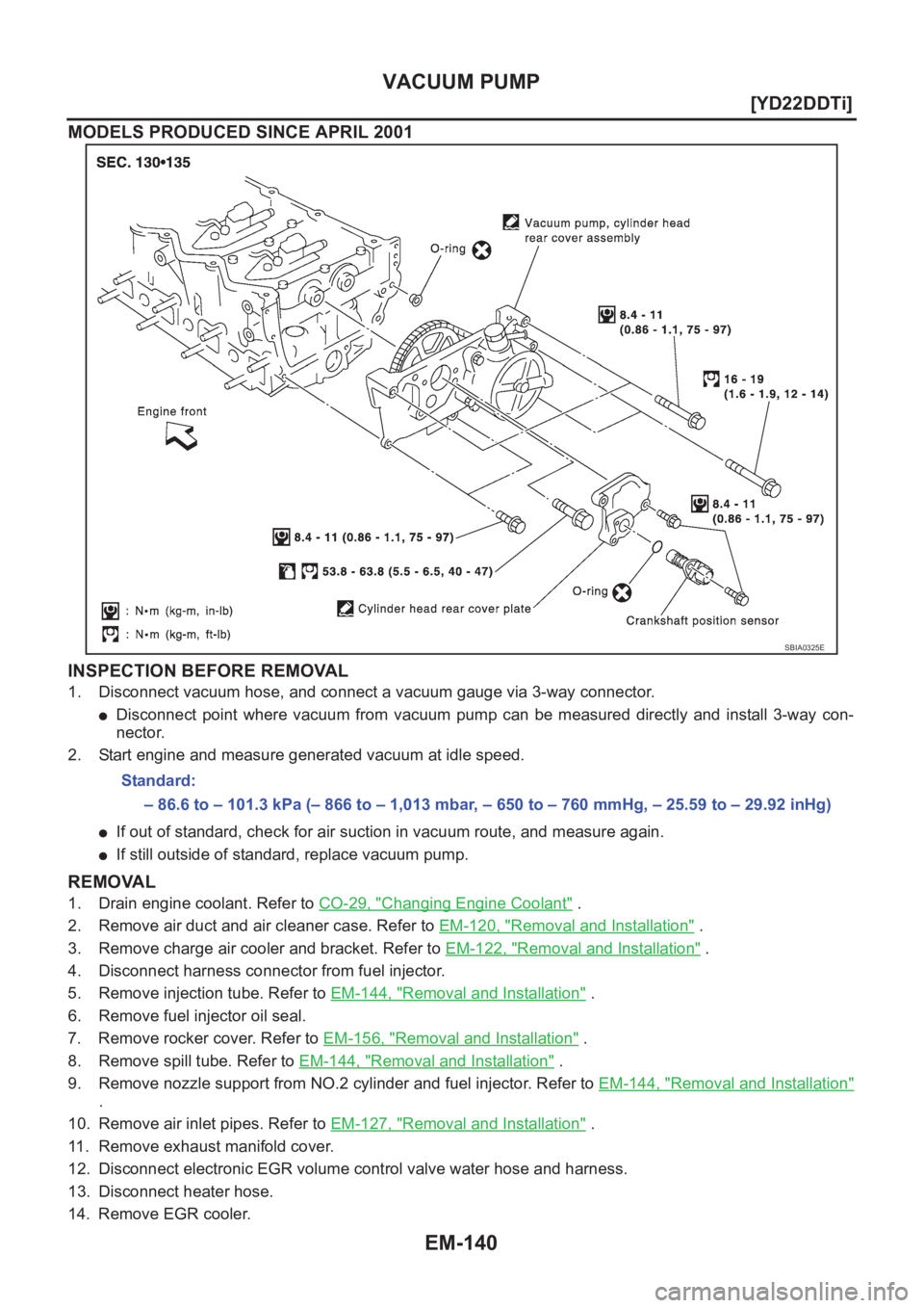
VACUUM PUMP
MODELS PRODUCED SINCE APRIL 2001
INSPECTION BEFORE REMOVAL
1. Disconnect vacuum hose, and connect a vacuum gauge via 3-way connector.
●Disconnect point where vacuum from vacuum pump can be measured directly and install 3-way con-
nector.
2. Start engine and measure generated vacuum at idle speed.
●If out of standard, check for air suction in vacuum route, and measure again.
●If still outside of standard, replace vacuum pump.
REMOVAL
1. Drain engine coolant. Refer to CO-29, "Changing Engine Coolant" .
2. Remove air duct and air cleaner case. Refer to EM-120, "
Removal and Installation" .
3. Remove charge air cooler and bracket. Refer to EM-122, "
Removal and Installation" .
4. Disconnect harness connector from fuel injector.
5. Remove injection tube. Refer to EM-144, "
Removal and Installation" .
6. Remove fuel injector oil seal.
7. Remove rocker cover. Refer to EM-156, "
Removal and Installation" .
8. Remove spill tube. Refer to EM-144, "
Removal and Installation" .
9. Remove nozzle support from NO.2 cylinder and fuel injector. Refer to EM-144, "
Removal and Installation"
.
10. Remove air inlet pipes. Refer to EM-127, "
Removal and Installation" .
11. Remove exhaust manifold cover.
12. Disconnect electronic EGR volume control valve water hose and harness.
13. Disconnect heater hose.
14. Remove EGR cooler.
SBIA0325E
Standard:
– 86.6 to – 101.3 kPa (– 866 to – 1,013 mbar, – 650 to – 760 mmHg, – 25.59 to – 29.92 inHg)