cooling NISSAN X-TRAIL 2003 Electronic Repair Manual
[x] Cancel search | Manufacturer: NISSAN, Model Year: 2003, Model line: X-TRAIL, Model: NISSAN X-TRAIL 2003Pages: 3066, PDF Size: 51.47 MB
Page 1879 of 3066
![NISSAN X-TRAIL 2003 Electronic Repair Manual DTC P1217 OVERHEAT (COOLING SYSTEM)
EC-765
[YD]
C
D
E
F
G
H
I
J
K
L
MA
EC
3.CHECK COOLING SYSTEM FOR LEAK
Apply pressure to the cooling system with a tester, and check if the pressure drops.
CAUTION:](/img/5/57402/w960_57402-1878.png "NISSAN X-TRAIL 2003 Electronic Repair Manual DTC P1217 OVERHEAT (COOLING SYSTEM)
EC-765
[YD]
C
D
E
F
G
H
I
J
K
L
MA
EC
3.CHECK COOLING SYSTEM FOR LEAK
Apply pressure to the cooling system with a tester, and check if the pressure drops.
CAUTION:")
DTC P1217 OVERHEAT (COOLING SYSTEM)
EC-765
[YD]
C
D
E
F
G
H
I
J
K
L
MA
EC
3.CHECK COOLING SYSTEM FOR LEAK
Apply pressure to the cooling system with a tester, and check if the pressure drops.
CAUTION:
Higher than the specified pressure may cause radiator damage.
OK or NG
OK >> GO TO 5.
NG >> GO TO 4.
4.DETECT MALFUNCTIONING PART
Check the following for leak.
lHose
lRadiator
lWater pump (Refer toCO-40, "WATER PUMP".)
>> Repair or replace.
5.CHECKRADIATORCAP
Apply pressure to cap with a tester and check radiator cap relief
pressure.
OK or NG
OK >> GO TO 6.
NG >> Replace radiator cap.Testing pressure: 157 kPa (1.57 bar, 1.6 kg/cm
2, 23psi)
Pressure should not drop.
SLC754A
Radiator cap relief pressure:
78 - 98 kPa (0.59 - 0.98 bar, 0.6 - 1.0 kg/cm
2,9-14psi)
SLC755A
Page 1880 of 3066
![NISSAN X-TRAIL 2003 Electronic Repair Manual EC-766
[YD]
DTC P1217 OVERHEAT (COOLING SYSTEM)
6.CHECK THERMOSTAT
1. Remove thermostat.
2. Check valve seating condition at normal room temperatures.
It should seat tightly.
3. Check valve opening te](/img/5/57402/w960_57402-1879.png "NISSAN X-TRAIL 2003 Electronic Repair Manual EC-766
[YD]
DTC P1217 OVERHEAT (COOLING SYSTEM)
6.CHECK THERMOSTAT
1. Remove thermostat.
2. Check valve seating condition at normal room temperatures.
It should seat tightly.
3. Check valve opening te")
EC-766
[YD]
DTC P1217 OVERHEAT (COOLING SYSTEM)
6.CHECK THERMOSTAT
1. Remove thermostat.
2. Check valve seating condition at normal room temperatures.
It should seat tightly.
3. Check valve opening temperature and valve lift.
4. Check if valve is closed at 5°C(9°F) below valve opening tem-
perature. For details, refer toCO-42, "
THERMOSTAT AND
WATER PIPING".
OK or NG
OK >> GO TO 7.
NG >> Replace thermostat.
7.CHECK ENGINE COOLANT TEMPERATURE SENSOR
Refer toEC-714, "
Component Inspection".
OK or NG
OK >> GO TO 8.
NG >> Replace engine coolant temperature sensor.
8.CHECK MAIN 12 CAUSES
If the cause cannot be isolated, go toEC-770, "
Main 12 Causes of Overheating".
>>INSPECTION END
PROCEDURE A
1.CHECK COOLING FAN POWER SUPPLY CIRCUIT
1. Turn ignition switch “OFF”.
2. Disconnect cooling fan relay-1.
3. Turn ignition switch “ON”.
4. Check voltage between cooling fan relay-1 terminals 1, 5, 7 and
ground with CONSULT-II or tester.
OK or NG
OK >> GO TO 3.
NG >> GO TO 2.Valve opening temperature:
80 - 84°C (176 - 183°F) [standard]
Valve lift:
More than 10 mm/95°C (0.339 in/203°F)
SLC343
Voltage: Battery voltage
PBIB0422E
Page 1881 of 3066
![NISSAN X-TRAIL 2003 Electronic Repair Manual DTC P1217 OVERHEAT (COOLING SYSTEM)
EC-767
[YD]
C
D
E
F
G
H
I
J
K
L
MA
EC
2.DETECT MALFUNCTIONING PART
Check the following.
lFuse block (J/B) connector E103
l10A fuse
l40A fusible links
lHarness for o](/img/5/57402/w960_57402-1880.png "NISSAN X-TRAIL 2003 Electronic Repair Manual DTC P1217 OVERHEAT (COOLING SYSTEM)
EC-767
[YD]
C
D
E
F
G
H
I
J
K
L
MA
EC
2.DETECT MALFUNCTIONING PART
Check the following.
lFuse block (J/B) connector E103
l10A fuse
l40A fusible links
lHarness for o")
DTC P1217 OVERHEAT (COOLING SYSTEM)
EC-767
[YD]
C
D
E
F
G
H
I
J
K
L
MA
EC
2.DETECT MALFUNCTIONING PART
Check the following.
lFuse block (J/B) connector E103
l10A fuse
l40A fusible links
lHarness for open or short between cooling fan relay-1 and fuse
lHarness for open or short between cooling fan relay-1 and battery
>> Repair open circuit or short to ground or short to power in harness or connectors.
3.CHECK COOLING FAN GROUND CIRCUIT FOR OPEN AND SHORT
1. Turn ignition switch “OFF”.
2. Disconnect cooling fan motor-1 harness connector and cooling fan motor-2 harness connector.
3. Check harness continuity between cooling fan relay-1 terminal 3 and cooling fan motor-1 terminal 1, cool-
ing fan motor-1 terminal 4 and body ground. Refer to Wiring Diagram.
4. Also check harness for short to ground and short to power.
5. Check harness continuity between cooling fan relay-1 terminal 6 and cooling fan motor-2 terminal 1, cool-
ing fan motor-2 terminal 4 and body ground. Refer to Wiring Diagram.
6. Also check harness for short to ground and short to power.
OK or NG
OK >> GO TO 4.
NG >> Repair open circuit or short to ground or short to power in harness or connectors.
4.CHECK COOLING FAN OUTPUT SIGNAL CIRCUIT FOR OPEN AND SHORT
1. Disconnect ECM harness connector.
2. Check harness continuity between ECM terminal E2 and cooling fan relay-1 terminal 2. Refer to Wiring
Diagram.
3. Also check harness for short to ground and short to power.
OK or NG
OK >> GO TO 6.
NG >> GO TO 5.
PBIB0479E
Continuity should exist.
Continuity should exist.
Continuity should exist.
Page 1882 of 3066
![NISSAN X-TRAIL 2003 Electronic Repair Manual EC-768
[YD]
DTC P1217 OVERHEAT (COOLING SYSTEM)
5.DETECT MALFUNCTIONING PART
Check the following.
lHarness connectors E64, F5
lHarness for open or short between cooling fan relay-1 and ECM
>> Repair o](/img/5/57402/w960_57402-1881.png "NISSAN X-TRAIL 2003 Electronic Repair Manual EC-768
[YD]
DTC P1217 OVERHEAT (COOLING SYSTEM)
5.DETECT MALFUNCTIONING PART
Check the following.
lHarness connectors E64, F5
lHarness for open or short between cooling fan relay-1 and ECM
>> Repair o")
EC-768
[YD]
DTC P1217 OVERHEAT (COOLING SYSTEM)
5.DETECT MALFUNCTIONING PART
Check the following.
lHarness connectors E64, F5
lHarness for open or short between cooling fan relay-1 and ECM
>> Repair open circuit or short to ground or short to power in harness or connectors.
6.CHECK COOLING FAN RELAY-1
Refer toEC-771, "
Component Inspection".
OK or NG
OK >> GO TO 7.
NG >> Replace cooling fan relay.
7.CHECK COOLING FAN MOTORS-1 AND -2
Refer toEC-771, "
Component Inspection".
OK or NG
OK >> GO TO 8.
NG >> Replace cooling fan motors.
8.CHECK INTERMITTENT INCIDENT
PerformEC-699, "
TROUBLE DIAGNOSIS FOR INTERMITTENT INCIDENT".
>>INSPECTION END
PROCEDURE B
1.CHECK COOLING FAN POWER SUPPLY CIRCUIT
1. Turn ignition switch “OFF”.
2. Disconnect cooling fan relays-2 and -3.
3. Turn ignition switch “ON”.
4. Check voltage between cooling fan relays-2 and -3 terminals 1,
3 and ground with CONSULT-II or tester.
OK or NG
OK >> GO TO 3.
NG >> GO TO 2.
PBIB0369E
Voltage: Battery voltage
PBIB0424E
Page 1883 of 3066
![NISSAN X-TRAIL 2003 Electronic Repair Manual DTC P1217 OVERHEAT (COOLING SYSTEM)
EC-769
[YD]
C
D
E
F
G
H
I
J
K
L
MA
EC
2.DETECT MALFUNCTIONING PART
Check the following.
lHarness for open or short between cooling fan relays-2 and -3 and fuse
lHar](/img/5/57402/w960_57402-1882.png "NISSAN X-TRAIL 2003 Electronic Repair Manual DTC P1217 OVERHEAT (COOLING SYSTEM)
EC-769
[YD]
C
D
E
F
G
H
I
J
K
L
MA
EC
2.DETECT MALFUNCTIONING PART
Check the following.
lHarness for open or short between cooling fan relays-2 and -3 and fuse
lHar")
DTC P1217 OVERHEAT (COOLING SYSTEM)
EC-769
[YD]
C
D
E
F
G
H
I
J
K
L
MA
EC
2.DETECT MALFUNCTIONING PART
Check the following.
lHarness for open or short between cooling fan relays-2 and -3 and fuse
lHarness for open or short between cooling fan relays-2 and -3 and fusible link
>> Repair harness or connectors.
3.CHECK COOLING FAN GROUND CIRCUIT FOR OPEN AND SHORT
1. Turn ignition switch “OFF”.
2. Disconnect cooling fan motor-1 harness connector and cooling fan motor-2 harness connector.
3. Check harness continuity between cooling fan relay-2 terminal 5 and cooling fan motor-1 terminal 2, cool-
ing fan relay-2 terminal 6 and cooling fan motor-1 terminal 3, cooling fan relay-2 terminal 7 and body
ground. Refer to Wiring Diagram.
4. Also check harness for short to ground and short to power.
5. Check harness continuity between cooling fan relay-3 terminal 5 and cooling fan motor-2 terminal 2, cool-
ing fan relay-3 terminal 6 and cooling fan motor-2 terminal 3, cooling fan relay-3 terminal 7 and body
ground. Refer to Wiring Diagram.
6. Also check harness for short to ground and short to power.
OK or NG
OK >> GO TO 4.
NG >> Repair open circuit or short to ground or short to power in harness or connectors.
4.CHECK COOLING FAN OUTPUT SIGNAL CIRCUIT FOR OPEN AND SHORT
1. Disconnect ECM harness connector.
2. Check harness continuity between ECM terminal E7 and cooling fan relay-2 terminal 2, cooling fan relay-
3 terminal 2. Refer to Wiring Diagram.
3. Also check harness for short to ground and short to power.
OK or NG
OK >> GO TO 6.
NG >> GO TO 5.
PBIB0479E
Continuity should exist.
Continuity should exist.
Continuity should exist.
Page 1884 of 3066
![NISSAN X-TRAIL 2003 Electronic Repair Manual EC-770
[YD]
DTC P1217 OVERHEAT (COOLING SYSTEM)
5.DETECT MALFUNCTIONING PART
Check the following.
lHarness connectors E64, F5
lHarness for open or short between cooling fan relays-2 and -3 and ECM
>>](/img/5/57402/w960_57402-1883.png "NISSAN X-TRAIL 2003 Electronic Repair Manual EC-770
[YD]
DTC P1217 OVERHEAT (COOLING SYSTEM)
5.DETECT MALFUNCTIONING PART
Check the following.
lHarness connectors E64, F5
lHarness for open or short between cooling fan relays-2 and -3 and ECM
>>")
EC-770
[YD]
DTC P1217 OVERHEAT (COOLING SYSTEM)
5.DETECT MALFUNCTIONING PART
Check the following.
lHarness connectors E64, F5
lHarness for open or short between cooling fan relays-2 and -3 and ECM
>> Repair open circuit or short to ground or short to power in harness or connectors.
6.CHECK COOLING FAN RELAYS-2 AND -3
Refer toEC-771, "
Component Inspection".
OK or NG
OK >> GO TO 7.
NG >> Replace cooling fan relays.
7.CHECK COOLING FAN MOTORS
Refer toEC-771, "
Component Inspection".
OK or NG
OK >> GO TO 8.
NG >> Replace cooling fan motors.
8.CHECK INTERMITTENT INCIDENT
PerformEC-699, "
TROUBLE DIAGNOSIS FOR INTERMITTENT INCIDENT".
>>INSPECTION END
Main 12 Causes of OverheatingEBS004QY
Engine Step Inspection item Equipment Condition Reference page
OFF 1
lBlocked radiator
lBlocked radiator grille
lBlocked bumper
lVisual No blocking —
2
lCoolant mixturelCoolant tester 50 - 50% coolant mixture SeeMA-17, "RECOM-
MENDED FLUIDS AND
LUBRICANTS".
3
lCoolant levellVisual Coolant up to MAX level
in reservoir tank and radi-
ator filler neckSeeMA-27, "Changing
Engine Coolant".
4
lRadiator caplPressure tester 78 - 98 kPa (0.78 - 0.98
bar, 0.8 - 1.0 kg/cm2,11-
14 psi)SeeCO-34, "
Checking
Radiator Cap".
ON*
25lCoolant leakslVisual No leaks SeeCO-30, "LEAK
CHECK".
ON*
26lThermostatlTouch the upper and
lower radiator hosesBoth hoses should be hot SeeCO-42, "THERMO-
STAT AND WATER PIP-
ING".
ON*
17lCooling fanlCONSULT-II Operating See Trouble Diagnosis for
DTC P1217,EC-713
.
OFF 8
lCombustion gas leaklColor checker chemi-
cal tester 4 Gas ana-
lyzerNegative —
Page 1885 of 3066
![NISSAN X-TRAIL 2003 Electronic Repair Manual DTC P1217 OVERHEAT (COOLING SYSTEM)
EC-771
[YD]
C
D
E
F
G
H
I
J
K
L
MA
EC
*1: Turn the ignition switch ON.
*2: Engine running at 3,000 rpm for 10 minutes.
*3: Drive at 90 km/h (55 MPH) for 30 minutes](/img/5/57402/w960_57402-1884.png "NISSAN X-TRAIL 2003 Electronic Repair Manual DTC P1217 OVERHEAT (COOLING SYSTEM)
EC-771
[YD]
C
D
E
F
G
H
I
J
K
L
MA
EC
*1: Turn the ignition switch ON.
*2: Engine running at 3,000 rpm for 10 minutes.
*3: Drive at 90 km/h (55 MPH) for 30 minutes")
DTC P1217 OVERHEAT (COOLING SYSTEM)
EC-771
[YD]
C
D
E
F
G
H
I
J
K
L
MA
EC
*1: Turn the ignition switch ON.
*2: Engine running at 3,000 rpm for 10 minutes.
*3: Drive at 90 km/h (55 MPH) for 30 minutes and then let idle for 10 minutes.
*4: After 60 minutes of cool down time.
For more information, refer toCO-26, "
OVERHEATING CAUSE ANALYSIS".
Component InspectionEBS004QZ
COOLING FAN RELAY-1, -2 AND -3
Check continuity between terminals 3 and 5, 6 and 7 under the fol-
lowing conditions.
COOLING FAN MOTOR-1 AND -2
Supply battery voltage between the following terminals and check
operation.
ON*39lCoolant temperature
gaugelVisual Gauge less than 3/4
when driving—
lCoolant overflow to
reservoir tanklVisual No overflow during driv-
ing and idlingSeeMA-27, "Changing
Engine Coolant".
OFF*
410lCoolant return from
reservoir tank to radia-
torlVisual Should be initial level in
reservoir tankSeeMA-28, "REFILLING
ENGINE COOLANT".
OFF 11
lCylinder headlStraight gauge feeler
gauge0.1mm (0.004 in) Maxi-
mum distortion (warping)SeeEM-173, "CYLIN-
DER HEAD".
12
lCylinder block and pis-
tonslVisual No scuffing on cylinder
walls or pistonSeeEM-188, "CYLIN-
DER BLOCK". Engine Step Inspection item Equipment Condition Reference page
Conditions Continuity
12V direct current supply between ter-
minals 1 and 2Ye s
No current supply No
SEF745U
SpeedTe r m i n a l s
(+) (–)
Cooling fan motor-1Low 1 4
High 1, 2 3, 4
Cooling fan motor-2Low 1 4
High 1, 2 3, 4
PBIB0423E
Page 2080 of 3066
![NISSAN X-TRAIL 2003 Electronic Repair Manual EM-110
[YD22DDTi]
DRIVE BELTS
DRIVE BELTS
PFP:02117
Checking Drive BeltsEBS00BNX
lBefore inspecting the engine, make sure the engine has cooled
down; wait approximately 30 minutes after the engine has](/img/5/57402/w960_57402-2079.png "NISSAN X-TRAIL 2003 Electronic Repair Manual EM-110
[YD22DDTi]
DRIVE BELTS
DRIVE BELTS
PFP:02117
Checking Drive BeltsEBS00BNX
lBefore inspecting the engine, make sure the engine has cooled
down; wait approximately 30 minutes after the engine has")
EM-110
[YD22DDTi]
DRIVE BELTS
DRIVE BELTS
PFP:02117
Checking Drive BeltsEBS00BNX
lBefore inspecting the engine, make sure the engine has cooled
down; wait approximately 30 minutes after the engine has been
stopped.
lVisually inspect all belts for wear, damage or cracks on contact-
ing surfaces and edge areas.
lWhen measuring deflection, apply 98 N (10 kg, 22 lb) at the
marked point ( ).
CAUTION:
lWhen checking belt deflection immediately after installa-
tion, first adjust it to the specified value. Then, after turn-
ing the crankshaft two turns or more, re-adjust to the
specified value to avoid variation in deflection between
pulleys.
lTighten idler pulley lock nut by hand and measure deflection without looseness.
Belt Deflection:
*: When engine is cold.
Tension AdjustmentEBS00BNY
lAdjust belts with the parts shown below.
CAUTION:
lWhen a new belt is installed as a replacement, adjust it to the value specified under “New” value
because of insufficient adaptability with pulley grooves.
lIf the belt deflection of the current belt is out of the “Limit for re-adjusting”, adjust to the
“Adjusted” value.
lWhen checking belt deflection immediately after installation, first adjust it to the specified value.
Then, after turning crankshaft two turns or more, re-adjust it to the specified value to avoid vari-
ation in deflection between pulleys.
lMake sure the belts are fully fitted into the pulley grooves during installation.
lHandle with care to avoid smearing the belts with oil or cooling water etc.
lDo not twist or bend the belts with strong force.
JEM249G
Applied beltBelt deflection with 98 N (10 kg, 22 lb) force applied* mm (in)
New Adjusted Limit for re-adjusting
Air conditioner compressor belt 4 - 5 (0.16 - 0.20) 6 - 7 (0.24 - 0.28) 8.5 (0.335)
Alternator and water pump belt 9.0 - 10.5 (0.354 - 0.413) 11.0 - 12.5 (0.433 - 0.492) 16.5 (0.650)
Applied belt Belt adjustment method
Air conditioner compressor belt Adjusting bolt on idler pulley
Alternator water pump belt Adjusting bolt on alternator
Page 2152 of 3066
![NISSAN X-TRAIL 2003 Electronic Repair Manual EM-182
[YD22DDTi]
CYLINDER HEAD
2. Machine cylinder head inner diameter at valve seat installation
position.
3. Heat cylinder head to approximately 110 to 130°C(230to
266°F) in oil bath.
4. After co](/img/5/57402/w960_57402-2151.png "NISSAN X-TRAIL 2003 Electronic Repair Manual EM-182
[YD22DDTi]
CYLINDER HEAD
2. Machine cylinder head inner diameter at valve seat installation
position.
3. Heat cylinder head to approximately 110 to 130°C(230to
266°F) in oil bath.
4. After co")
EM-182
[YD22DDTi]
CYLINDER HEAD
2. Machine cylinder head inner diameter at valve seat installation
position.
3. Heat cylinder head to approximately 110 to 130°C(230to
266°F) in oil bath.
4. After cooling valve seats sufficiently with dry ice, press fit it to cylinder head.
CAUTION:
Do not touch the cooled valve seats directly by hand.
5. Using valve seat cutter, finish processing referring to the dimen-
sions shown in the figure.
CAUTION:
When using valve seat cutter, grasp cutter handle with both
hands, press cutter onto contacting face all around, and cut
thoroughly. If cutter is pressed unevenly or repeatedly, the
valve seat surface may be damaged.
6. Using compound, perform valve fitting.
7. Check again to make sure that contacting status is satisfactory.
For details, Refer toEM-181, "
Valve Seat Contact". Machining dimension:
Intake
30.500 - 30.516 mm (1.2008 - 1.2014 in) dia.
Exhaust
29.500 - 29.516 mm (1.1614 - 1.1620 in) dia.
SEM795A
FEM075
SBIA0197E
Page 2360 of 3066
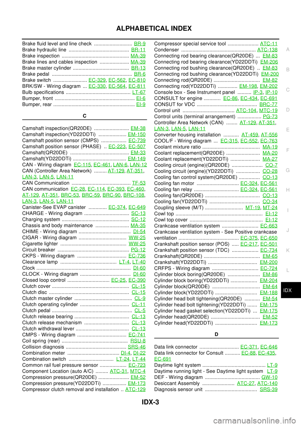
IDX-3
A
C
D
E
F
G
H
I
J
K
L B
IDX
ALPHABETICAL INDEX
Brake fluid level and line check ...........................BR-9
Brake hydraulic line ...........................................BR-11
Brake inspection ................................................MA-39
Brake lines and cables inspection .....................MA-39
Brake master cylinder ........................................BR-13
Brake pedal .........................................................BR-6
Brake switch ........................EC-329,EC-562,EC-810
BRK/SW - Wiring diagram ...EC-330,EC-564,EC-811
Bulb specifications ..............................................LT-67
Bumper, front .........................................................EI-6
Bumper, rear ..........................................................EI-9
C
Camshaft inspection(QR20DE) .........................EM-38
Camshaft inspection(YD22DDTi) ....................EM-150
Camshaft position sensor (CMPS) ..................EC-739
Camshaft position sensor (PHASE) ..EC-223,EC-507
Camshaft(QR20DE) ..........................................EM-33
Camshaft(YD22DDTi) ......................................EM-149
CAN - Wiring diagramEC-115,EC-461,LAN-6,LAN-12
CAN (Controller Area Network) .........AT-129,AT-351,
LAN-3
,LAN-5,LAN-11
CAN Communication ..........................................TF-53
CAN communicationEC-28,EC-114,EC-393,EC-460,
AT-129
,AT-351,BRC-53,BRC-59,BRC-90,BRC-108,
LAN-3
,LAN-5,LAN-11
Canister-See EVAP canister .............EC-374,EC-649
CHARGE - Wiring diagram ................................SC-13
Charging system ................................................SC-12
Chassis and body maintenance ........................MA-35
CHIME - Wiring diagram .....................................DI-54
CIGAR - Wiring diagram ..................................WW-25
Cigarette lighter ...............................................WW-25
Circuit breaker ...................................................PG-12
CKPS - Wiring diagram ...................................EC-736
Clearance lamp ........................................LT-4,LT-40
Clock ...................................................................DI-60
CLOCK - Wiring diagram ....................................DI-60
Closed loop control ..............................EC-25,EC-390
Clutch cover .......................................................CL-15
Clutch disc .........................................................CL-15
Clutch master cylinder .........................................CL-9
Clutch operating cylinder ...................................CL-11
Clutch pedal .........................................................CL-5
Clutch release bearing .......................................CL-13
Clutch release mechanism ................................CL-13
Clutch withdrawal lever ......................................CL-13
CMPS - Wiring diagram ...................................EC-741
Coil spring (rear) ...............................................RSU-8
Collision diagnosis ...........................................SRS-46
Combination meter .....................................DI-4,DI-22
Combination switch ................................LT-24,LT-44
Common rail fuel pressure sensor ...................EC-723
Component Location (auto A/C) .........ATC-31,MTC-4
Compression pressure(QR20DE) ......................EM-52
Compression pressure(YD22DDTi) .................EM-173
Compressor clutch removal and installation ..ATC-129
Compressor special service tool ......................ATC-11
Condenser .....................................................ATC-138
Connecting rod bearing clearance(QR20DE) ...EM-83
Connecting rod bearing clearance(YD22DDTi)EM-206
Connecting rod bushing clearance(QR20DE) ..EM-83
Connecting rod bushing clearance(YD22DDTi)EM-200
Connecting rod(QR20DE) .................................EM-82
Connecting rod(YD22DDTi) ..............EM-198,EM-202
Console box - See Instrument panel ..........IP-3,IP-10
CONSULT for engine ............EC-86,EC-434,EC-691
CONSUT for VDC ...........................................BRC-77
Control unit .....................................ATC-104,MTC-19
Control units (terminal arrangement) .................PG-73
Controller Area Network (CAN) ........AT-129,AT-351,
LAN-3
,LAN-5,LAN-11
Converter housing installation ...........AT-459,AT-556
COOL/F - Wiring diagram ...EC-315,EC-552,EC-763
Coolant mixture ratio .........................................MA-19
Coolant replacement(QR20DE) ........................MA-20
Coolant replacement(YD22DDTi) .....................MA-27
Cooling circuit (engine)(QR20DE) ......................CO-7
Cooling circuit (engine)(YD22DDTi) .................CO-28
Cooling fan control system(QR20DE) ...............CO-13
Cooling fan motor ..............................EC-324,EC-561
Cooling fan relay ................................EC-324,EC-561
Cooling fan(QR20DE) .......................................CO-13
Cooling fan(YD22DDTi) ....................................CO-34
Coupling sleeve (M/T) ...........................MT-19,MT-24
Cowl top ..............................................................EI-12
Cowl top cover ....................................................EI-12
Crankcase ventilation system ..........................EC-663
Crankcase ventilation system - See Positive crankcase
ventilation ...........................................EC-375
,EC-650
Crankshaft position sensor (POS) .....EC-217,EC-501
Crankshaft position sensor (TDC) ...................EC-734
Crankshaft(QR20DE) ........................................EM-65
Crankshaft(YD22DDTi) ...................................EM-200
CRFPS - Wiring diagram .................................EC-724
Cylinder block boring(QR20DE) .......................EM-86
Cylinder block boring(YD22DDTi) ...................EM-204
Cylinder block(QR20DE) ..................................EM-64
Cylinder block(YD22DDTi) ..............................EM-188
Cylinder head bolt tightening(QR20DE) ...........EM-54
Cylinder head bolt tightening(YD22DDTi) .......EM-175
Cylinder head gasket selection(YD22DDTi) ...EM-175
Cylinder head(QR20DE) ...................................EM-52
Cylinder head(YD22DDTi) ..............................EM-173
D
Data link connector ............................EC-371
,EC-646
Data link connector for Consult ...........EC-88,EC-435,
EC-691
Daytime light system .............................................LT-9
Daytime running light - See Daytime light systemLT-9
DEF - Wiring diagram .......................................GW-10
Desiccant Assembly .......................ATC-27,ATC-140
Diagnosis sensor unit .....................................SRS-39