air bleeding NISSAN X-TRAIL 2003 Electronic Repair Manual
[x] Cancel search | Manufacturer: NISSAN, Model Year: 2003, Model line: X-TRAIL, Model: NISSAN X-TRAIL 2003Pages: 3066, PDF Size: 51.47 MB
Page 835 of 3066

BR-1
BRAKE SYSTEM
F BRAKES
CONTENTS
C
D
E
G
H
I
J
K
L
M
SECTION
A
B
BR
BRAKE SYSTEM
PRECAUTIONS .......................................................... 3
Precautions for Models with SRS Air Bag and Pre-
Tensioner Seat Belt .................................................. 3
Precautions for Brake System .................................. 3
PREPARATION ........................................................... 4
Special Service Tools ............................................... 4
NOISE, VIBRATION, AND HARSHNESS (NVH)
TROUBLESHOOTING ................................................ 5
NVH Troubleshooting Chart ..................................... 5
BRAKE PEDAL .......................................................... 6
On-Vehicle Inspection and Adjustment .................... 6
Components ............................................................. 7
Removal and Installation .......................................... 7
REMOVAL ............................................................. 7
INSPECTION AFTER REMOVAL ......................... 8
INSTALLATION ..................................................... 8
BRAKE FLUID ............................................................ 9
Checking Brake Fluid Level ..................................... 9
Checking Brake Line ................................................ 9
Changing Brake Fluid ............................................... 9
Brake Burnishing Procedure .................................. 10
Bleeding Brake System .......................................... 10
BRAKE PIPING AND HOSE .....................................11
Hydraulic Piping ......................................................11
Removal and Installation of Front Brake Piping and
Brake Hose .............................................................11
REMOVAL ............................................................11
INSTALLATION ....................................................11
Removal and Installation of Rear Brake Piping and
Brake Hose ............................................................ 12
REMOVAL ........................................................... 12
INSTALLATION ................................................... 12
Inspection ............................................................... 12
BRAKE MASTER CYLINDER .................................. 13
Components ........................................................... 13
Removal and Installation ........................................ 13
REMOVAL ........................................................... 13INSTALLATION ................................................... 13
Disassembly and Assembly .................................... 14
DISASSEMBLY ................................................... 14
INSPECTION AFTER REMOVAL ....................... 14
ASSEMBLY ......................................................... 15
BRAKE BOOSTER ................................................... 17
On-Vehicle Inspection and Service ......................... 17
FUNCTION INSPECTION ................................... 17
AIRTIGHTNESS INSPECTION ........................... 17
Removal and Installation ........................................ 17
REMOVAL ........................................................... 17
INSPECTION AFTER REMOVAL ....................... 17
INSTALLATION ................................................... 18
VACUUM LINES ....................................................... 19
Removal and Installation ........................................ 19
Inspection ............................................................... 19
VISUAL INSPECTION ......................................... 19
CHECK VALVE INSPECTION ............................. 20
FRONT DISC BRAKE ............................................... 21
Component ............................................................. 21
Inspection ............................................................... 21
PAD THICKNESS ................................................ 21
Pad Replacement ................................................... 22
REMOVAL ........................................................... 22
INSTALLATION ................................................... 22
Caliper Removal and Installation ............................ 22
REMOVAL ........................................................... 22
INSTALLATION ................................................... 23
Caliper Disassembly and Assembly ....................... 23
DISASSEMBLY ................................................... 23
INSPECTION AFTER DISASSEMBLY ................ 24
DISC ROTOR INSPECTION ............................... 24
ASSEMBLY ......................................................... 25
BRAKE BURNISHING PROCEDURE ................. 25
REAR DISC BRAKE ................................................. 27
Component ............................................................. 27
Inspection ............................................................... 27
PAD WEAR INSPECTION ................................... 27
Pad Replacement ................................................... 28
REMOVAL ........................................................... 28
Page 844 of 3066
BR-10
BRAKE FLUID
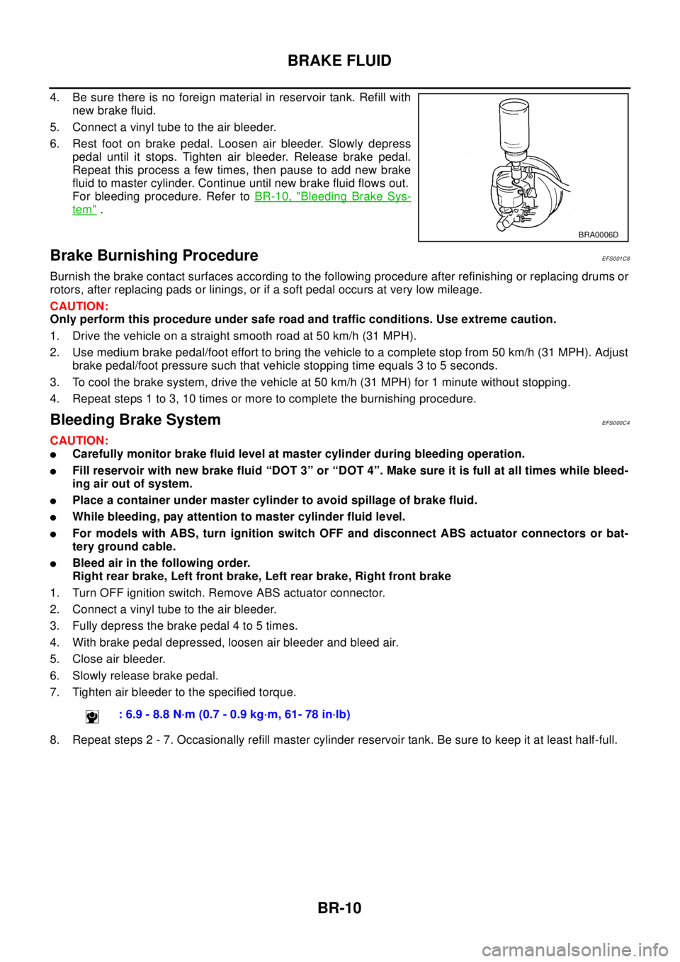
4. Be sure there is no foreign material in reservoir tank. Refill with
new brake fluid.
5. Connect a vinyl tube to the air bleeder.
6. Rest foot on brake pedal. Loosen air bleeder. Slowly depress
pedal until it stops. Tighten air bleeder. Release brake pedal.
Repeat this process a few times, then pause to add new brake
fluid to master cylinder. Continue until new brake fluid flows out.
For bleeding procedure. Refer toBR-10, "
Bleeding Brake Sys-
tem".
Brake Burnishing ProcedureEFS001C8
Burnish the brake contact surfaces according to the following procedure after refinishing or replacing drums or
rotors, after replacing pads or linings, or if a soft pedal occurs at very low mileage.
CAUTION:
Only perform this procedure under safe road and traffic conditions. Use extreme caution.
1. Drive the vehicle on a straight smooth road at 50 km/h (31 MPH).
2. Use medium brake pedal/foot effort to bring the vehicle to a complete stop from 50 km/h (31 MPH). Adjust
brake pedal/foot pressure such that vehicle stopping time equals 3 to 5 seconds.
3. To cool the brake system, drive the vehicle at 50 km/h (31 MPH) for 1 minute without stopping.
4. Repeat steps 1 to 3, 10 times or more to complete the burnishing procedure.
Bleeding Brake SystemEFS000C4
CAUTION:
lCarefully monitor brake fluid level at master cylinder during bleeding operation.
lFill reservoir with new brake fluid “DOT 3” or “DOT 4”. Make sure it is full at all times while bleed-
ing air out of system.
lPlace a container under master cylinder to avoid spillage of brake fluid.
lWhile bleeding, pay attention to master cylinder fluid level.
lFor models with ABS, turn ignition switch OFF and disconnect ABS actuator connectors or bat-
tery ground cable.
lBleed air in the following order.
Right rear brake, Left front brake, Left rear brake, Right front brake
1. Turn OFF ignition switch. Remove ABS actuator connector.
2. Connect a vinyl tube to the air bleeder.
3. Fully depress the brake pedal 4 to 5 times.
4. With brake pedal depressed, loosen air bleeder and bleed air.
5. Close air bleeder.
6. Slowly release brake pedal.
7. Tighten air bleeder to the specified torque.
8. Repeat steps 2 - 7. Occasionally refill master cylinder reservoir tank. Be sure to keep it at least half-full.
BRA0006D
: 6.9 - 8.8 N·m (0.7 - 0.9 kg·m, 61- 78 in·lb)
Page 852 of 3066
BR-18
BRAKE BOOSTER
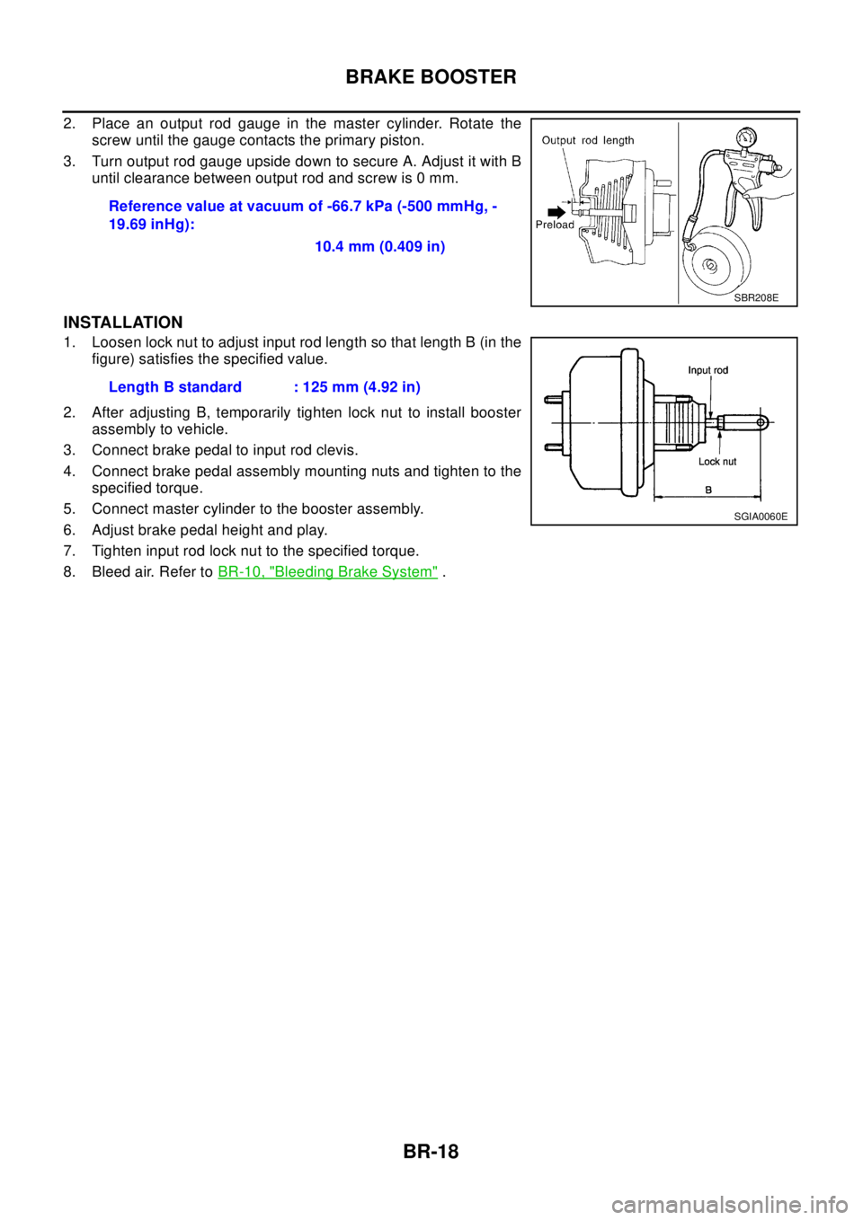
2. Place an output rod gauge in the master cylinder. Rotate the
screw until the gauge contacts the primary piston.
3. Turn output rod gauge upside down to secure A. Adjust it with B
until clearance between output rod and screw is 0 mm.
INSTALLATION
1. Loosen lock nut to adjust input rod length so that length B (in the
figure) satisfies the specified value.
2. After adjusting B, temporarily tighten lock nut to install booster
assembly to vehicle.
3. Connect brake pedal to input rod clevis.
4. Connect brake pedal assembly mounting nuts and tighten to the
specified torque.
5. Connect master cylinder to the booster assembly.
6. Adjust brake pedal height and play.
7. Tighten input rod lock nut to the specified torque.
8. Bleed air. Refer toBR-10, "
Bleeding Brake System". Reference value at vacuum of -66.7 kPa (-500 mmHg, -
19.69 inHg):
10.4 mm (0.409 in)
SBR208E
Length B standard : 125 mm (4.92 in)
SGIA0060E
Page 857 of 3066
FRONT DISC BRAKE
BR-23
C
D
E
G
H
I
J
K
L
MA
B
BR
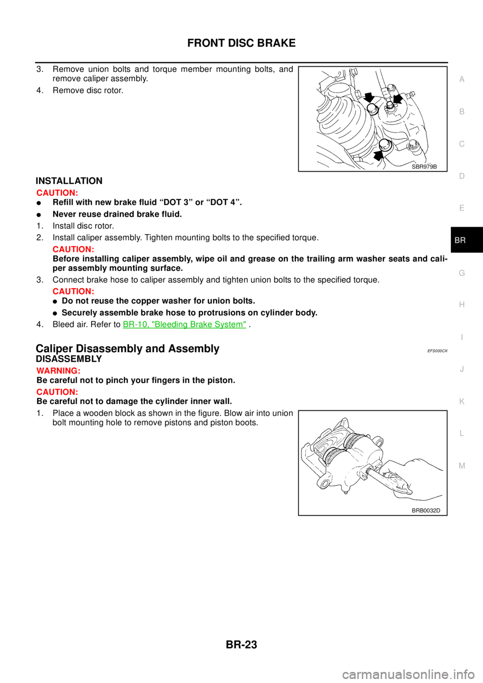
3. Remove union bolts and torque member mounting bolts, and
remove caliper assembly.
4. Remove disc rotor.
INSTALLATION
CAUTION:
lRefill with new brake fluid “DOT 3” or “DOT 4”.
lNever reuse drained brake fluid.
1. Install disc rotor.
2. Install caliper assembly. Tighten mounting bolts to the specified torque.
CAUTION:
Before installing caliper assembly, wipe oil and grease on the trailing arm washer seats and cali-
per assembly mounting surface.
3. Connect brake hose to caliper assembly and tighten union bolts to the specified torque.
CAUTION:
lDo not reuse the copper washer for union bolts.
lSecurely assemble brake hose to protrusions on cylinder body.
4. Bleed air. Refer toBR-10, "
Bleeding Brake System".
Caliper Disassembly and AssemblyEF S0 00 CK
DISASSEMBLY
WA RN ING:
Be careful not to pinch your fingers in the piston.
CAUTION:
Be careful not to damage the cylinder inner wall.
1. Place a wooden block as shown in the figure. Blow air into union
bolt mounting hole to remove pistons and piston boots.
SBR979B
BRB0032D
Page 863 of 3066
REAR DISC BRAKE
BR-29
C
D
E
G
H
I
J
K
L
MA
B
BR
Caliper Removal and InstallationEFS00180
REMOVAL
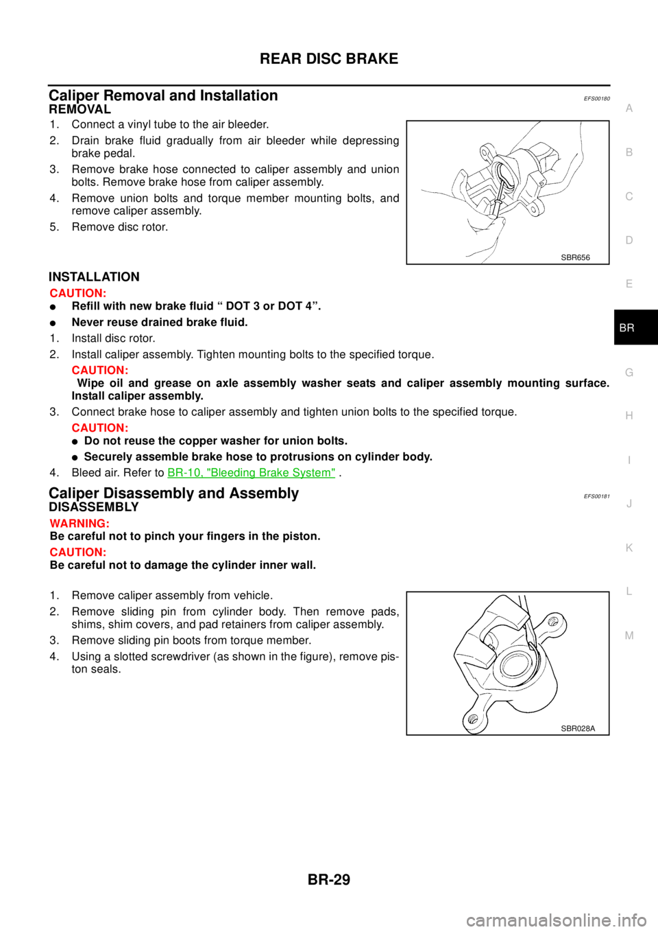
1. Connect a vinyl tube to the air bleeder.
2. Drain brake fluid gradually from air bleeder while depressing
brake pedal.
3. Remove brake hose connected to caliper assembly and union
bolts. Remove brake hose from caliper assembly.
4. Remove union bolts and torque member mounting bolts, and
remove caliper assembly.
5. Remove disc rotor.
INSTALLATION
CAUTION:
lRefill with new brake fluid “ DOT 3 or DOT 4”.
lNever reuse drained brake fluid.
1. Install disc rotor.
2. Install caliper assembly. Tighten mounting bolts to the specified torque.
CAUTION:
Wipe oil and grease on axle assembly washer seats and caliper assembly mounting surface.
Install caliper assembly.
3. Connect brake hose to caliper assembly and tighten union bolts to the specified torque.
CAUTION:
lDo not reuse the copper washer for union bolts.
lSecurely assemble brake hose to protrusions on cylinder body.
4. Bleed air. Refer toBR-10, "
Bleeding Brake System".
Caliper Disassembly and AssemblyEFS00181
DISASSEMBLY
WA RN ING:
Be careful not to pinch your fingers in the piston.
CAUTION:
Be careful not to damage the cylinder inner wall.
1. Remove caliper assembly from vehicle.
2. Remove sliding pin from cylinder body. Then remove pads,
shims, shim covers, and pad retainers from caliper assembly.
3. Remove sliding pin boots from torque member.
4. Using a slotted screwdriver (as shown in the figure), remove pis-
ton seals.
SBR656
SBR028A
Page 866 of 3066
BR-32
REAR DISC BRAKE
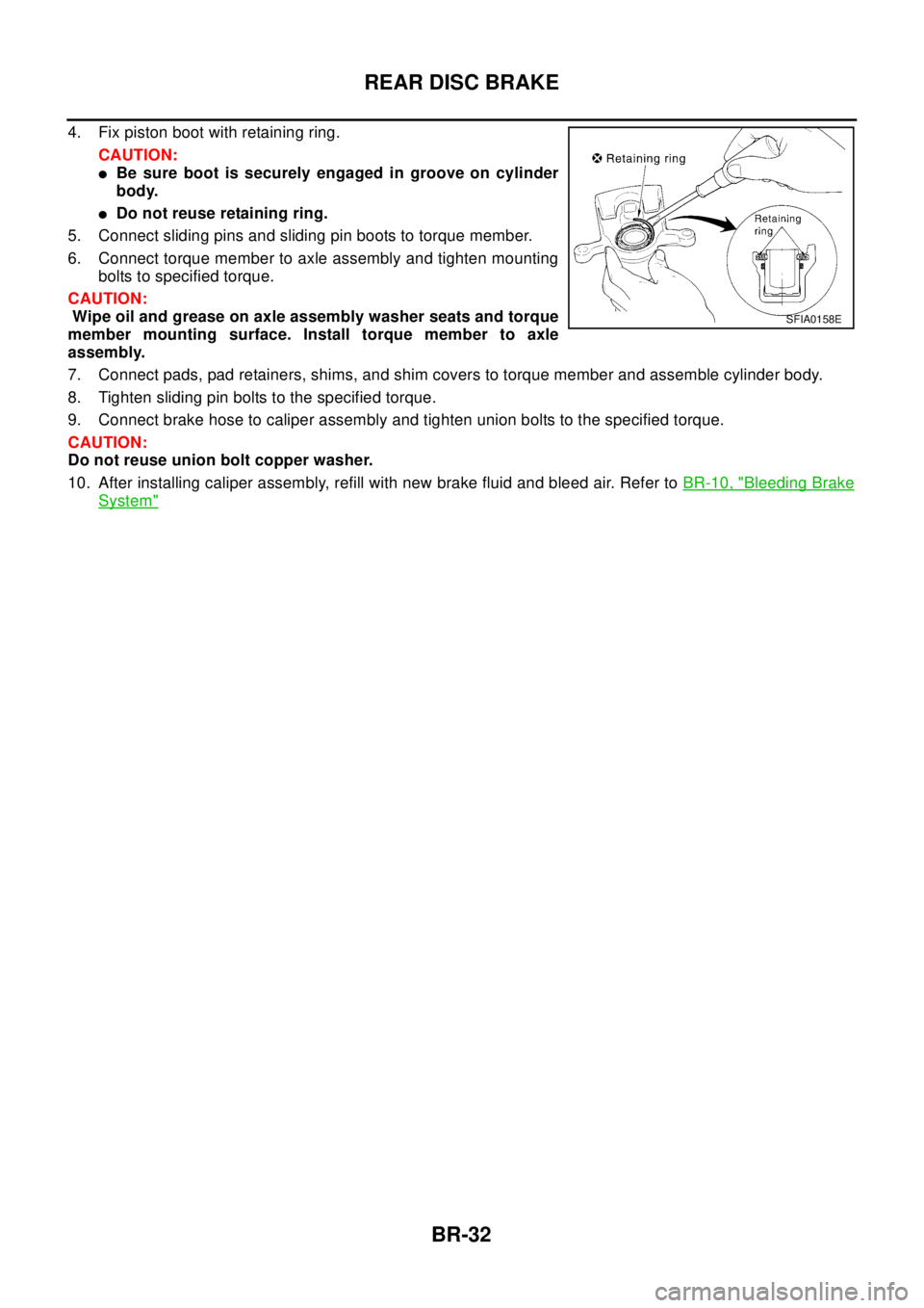
4. Fix piston boot with retaining ring.
CAUTION:
lBe sure boot is securely engaged in groove on cylinder
body.
lDo not reuse retaining ring.
5. Connect sliding pins and sliding pin boots to torque member.
6. Connect torque member to axle assembly and tighten mounting
bolts to specified torque.
CAUTION:
Wipe oil and grease on axle assembly washer seats and torque
member mounting surface. Install torque member to axle
assembly.
7. Connect pads, pad retainers, shims, and shim covers to torque member and assemble cylinder body.
8. Tighten sliding pin bolts to the specified torque.
9. Connect brake hose to caliper assembly and tighten union bolts to the specified torque.
CAUTION:
Do not reuse union bolt copper washer.
10. After installing caliper assembly, refill with new brake fluid and bleed air. Refer toBR-10, "
Bleeding Brake
System"
SFIA0158E
Page 980 of 3066
![NISSAN X-TRAIL 2003 Electronic Repair Manual BRC-112
[ESP/TCS/ABS]
TROUBLE DIAGNOSIS
Actuator operation check
1. Connect 19 and 21 terminals of actuator to 40 and 41 terminals
of relay box.
2. Measure the motor voltage (No.4 terminal to body ear NISSAN X-TRAIL 2003 Electronic Repair Manual BRC-112
[ESP/TCS/ABS]
TROUBLE DIAGNOSIS
Actuator operation check
1. Connect 19 and 21 terminals of actuator to 40 and 41 terminals
of relay box.
2. Measure the motor voltage (No.4 terminal to body ear](/img/5/57402/w960_57402-979.png)
BRC-112
[ESP/TCS/ABS]
TROUBLE DIAGNOSIS
Actuator operation check
1. Connect 19 and 21 terminals of actuator to 40 and 41 terminals
of relay box.
2. Measure the motor voltage (No.4 terminal to body earth ) with
oscilloscope. Then check the motor reverse voltage occasioned
time.
The motor reverse voltage occasioned time is more than 0.1
sec.
CAUTION:
lPerform checking of motor relay unit .Then confirm that
relay functions.
lDriving actuator motor is with in 4 sec to prevent heating
up.
lStandard condition of the motor reverse voltage occa-
sioned time is: Battery voltage is 12V. temperature 20°.
when the battery voltage or temperature is lower than the
standard, the motor reverse voltage occasioned time
becomesslightlyshorter.
Symptom 1: ABS Works Frequently.EFS001AS
Inspection procedure
1.INSPECTION START
Check the wheel speed sensor system.
lSensor mounting inspection
lSensor pick-up inspection for iron chips
lSensor rotor inspection (e.g. number of teeth, damaged teeth)
lSensor connector engagement inspection
Is inspection result OK?
YES >> GO TO 2.
NO >> Refer to wheel speed sensor and rotor lines.
2.LOOSENESS INSPECTION
Check the front axle for looseness.
Is inspection result OK?
YES >>BRC-112, "Symptom 2: Unexpected Pedal Action"
NO >> Axle inspection and repair
Symptom 2: Unexpected Pedal ActionEFS001AT
Inspection procedure
1.BRAKE PEDAL STROKE INSPECTION
Check the brake pedal stroke.
Is stroke excessively long?
YES >> Check the bleeding and brake system.
NO >> GO TO 2.
SFIA0400E
Page 981 of 3066
![NISSAN X-TRAIL 2003 Electronic Repair Manual TROUBLE DIAGNOSIS
BRC-113
[ESP/TCS/ABS]
C
D
E
G
H
I
J
K
L
MA
B
BRC
2.PEDAL FORCE INSPECTION
Check that the brake is effective with the pedal depressed.
Is the pedal heavy, but effective?
YES >> Normal NISSAN X-TRAIL 2003 Electronic Repair Manual TROUBLE DIAGNOSIS
BRC-113
[ESP/TCS/ABS]
C
D
E
G
H
I
J
K
L
MA
B
BRC
2.PEDAL FORCE INSPECTION
Check that the brake is effective with the pedal depressed.
Is the pedal heavy, but effective?
YES >> Normal](/img/5/57402/w960_57402-980.png)
TROUBLE DIAGNOSIS
BRC-113
[ESP/TCS/ABS]
C
D
E
G
H
I
J
K
L
MA
B
BRC
2.PEDAL FORCE INSPECTION
Check that the brake is effective with the pedal depressed.
Is the pedal heavy, but effective?
YES >> Normal
NO >> GO TO 3.
3.CONNECTOR AND PERFORMANCE INSPECTION
Disconnect the actuator relay unit connector to deactivate the ABS function. Check that the brake is effective.
Is the brake effective?
YES >> GO TO 4.
NO >> Brake line inspection
4.ABS WARNING LAMP INDICATOR INSPECTION
Check that the ABS warning lamp illuminates.
Does the ABS warning lamp illuminate?
YES >> Perform the self-diagnosis.
NO >> GO TO 5.
5.WHEEL SPEED SENSOR INSPECTION
Check the wheel speed sensor system.
lSensor mounting inspection
lSensor pick-up inspection for iron chips
lSensor rotor inspection (e.g. Number of teeth, damaged teeth)
lSensor connector engagement inspection
Is inspection result OK?
YES >> Normal
NO >> Wheel speed sensor and rotor lines repair
Symptom 3: Longer Stopping DistanceEFS001AU
Inspection procedure
1.INSPECTION START
Check that the stopping distance when braking becomes longer only on a snowy or gravel road.
Does the stopping distance when braking become longer only on a snowy or gravel road?
YES >> It may be longer than that of vehicle without ABS.
NO >> GO TO 2.
2.PERFORMANCE CHECK
Disconnect the actuator relay box to deactivate the ABS function.
Is the stopping distance still longer?
YES >>lBrake line air bleeding
lBrake line inspection
NO >> GO TO 3.
3.ABS WARNING LAMP INDICATOR INSPECTION
Check that the ABS warning lamp illuminates.
Does the ABS warning lamp illuminate?
YES >> Perform the self-diagnosis.
NO >> GO TO 4.
Page 993 of 3066

CL-1
CLUTCH
C TRANSMISSION/TRANSAXLE
CONTENTS
D
E
F
G
H
I
J
K
L
M
SECTION
A
B
CL
CLUTCH
PRECAUTIONS .......................................................... 2
Caution ..................................................................... 2
PREPARATION ........................................................... 3
Special Service Tools ............................................... 3
Commercial Service Tool ......................................... 3
NOISE, VIBRATION, AND HARSHNESS (NVH)
TROUBLESHOOTING ................................................ 4
NVH Troubleshooting Chart ..................................... 4
CLUTCH PEDAL ........................................................ 5
On-vehicle Inspection and Adjustment ..................... 5
HEIGHT ADJUSTMENT ....................................... 5
CLUTCH SWITCH POSITION ADJUSTMENT ..... 5
FREE PLAY INSPECTION .................................... 6
CLEARANCE CHECK ........................................... 6
Removal and Installation .......................................... 6
INSPECTION AFTER REMOVAL ......................... 7
CLUTCH FLUID .......................................................... 8
Air Bleeding Procedure ............................................ 8
CLUTCH MASTER CYLINDER .................................. 9
Removal and Installation .......................................... 9
REMOVAL ............................................................. 9
INSTALLATION ..................................................... 9
Disassembly and Assembly ................................... 10
DISASSEMBLY ................................................... 10
INSPECTION AFTER DISASSEMBLY ............... 10
ASSEMBLY ......................................................... 10
OPERATING CYLINDER ...........................................11Removal and Installation ........................................ 11
REMOVAL ........................................................... 11
INSTALLATION ................................................... 11
Disassembly and Assembly .................................... 11
DISASSEMBLY ................................................... 11
INSPECTION AFTER DISASSEMBLY ................ 11
ASSEMBLY ......................................................... 11
CLUTCH PIPING ....................................................... 12
Removal and Installation ........................................ 12
CLUTCH RELEASE MECHANISM ........................... 13
Removal and Installation ........................................ 13
REMOVAL ........................................................... 13
INSPECTION AFTER REMOVEL ....................... 13
INSTALLATION ................................................... 13
CLUTCH DISC, CLUTCH COVER AND FLYWHEEL... 15
Removal and Installation ........................................ 15
REMOBAL ........................................................... 15
INSPECTION AND ADJUSTMENT AFTER
REMOVAL ........................................................... 15
INSTALLATION ................................................... 16
SERVICE DATA AND SPECIFICATIONS (SDS) ...... 17
Clutch Control System ............................................ 17
Clutch Master Cylinder ........................................... 17
Clutch Operating Cylinder ...................................... 17
Clutch Disk ............................................................. 17
Clutch Cover ........................................................... 17
Clutch Pedal ........................................................... 17
Page 1000 of 3066
CL-8
CLUTCH FLUID
CLUTCH FLUID
PFP:00017
Air Bleeding ProcedureECS001WD
CAUTION:
lMonitor fluid level in the reservoir to make sure it does not empty.
lDo not spill clutch fluid onto painted surfaces. If it spills, wipe up immediately and wash the
affected area with water.
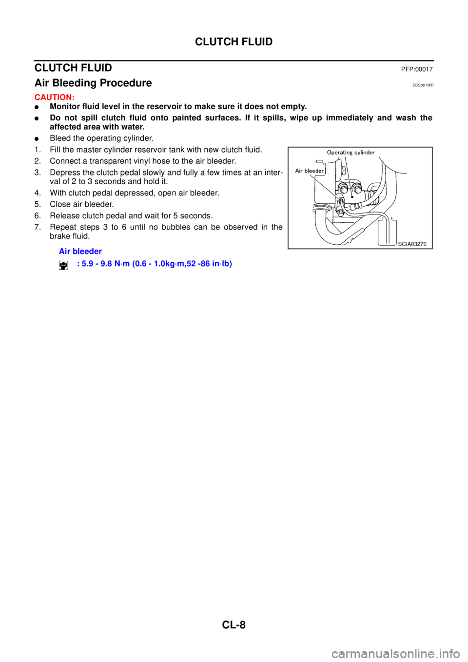
lBleed the operating cylinder.
1. Fill the master cylinder reservoir tank with new clutch fluid.
2. Connect a transparent vinyl hose to the air bleeder.
3. Depress the clutch pedal slowly and fully a few times at an inter-
val of 2 to 3 seconds and hold it.
4. With clutch pedal depressed, open air bleeder.
5. Close air bleeder.
6. Release clutch pedal and wait for 5 seconds.
7. Repeat steps 3 to 6 until no bubbles can be observed in the
brake fluid.
Air bleeder
: 5.9 - 9.8 N·m (0.6 - 1.0kg·m,52 -86 in·lb)
SCIA0327E