heater NISSAN X-TRAIL 2003 Electronic User Guide
[x] Cancel search | Manufacturer: NISSAN, Model Year: 2003, Model line: X-TRAIL, Model: NISSAN X-TRAIL 2003Pages: 3066, PDF Size: 51.47 MB
Page 703 of 3066
REFRIGERANT LINES
ATC-125
C
D
E
F
G
H
I
K
L
MA
B
AT C
ComponentsEJS000V8
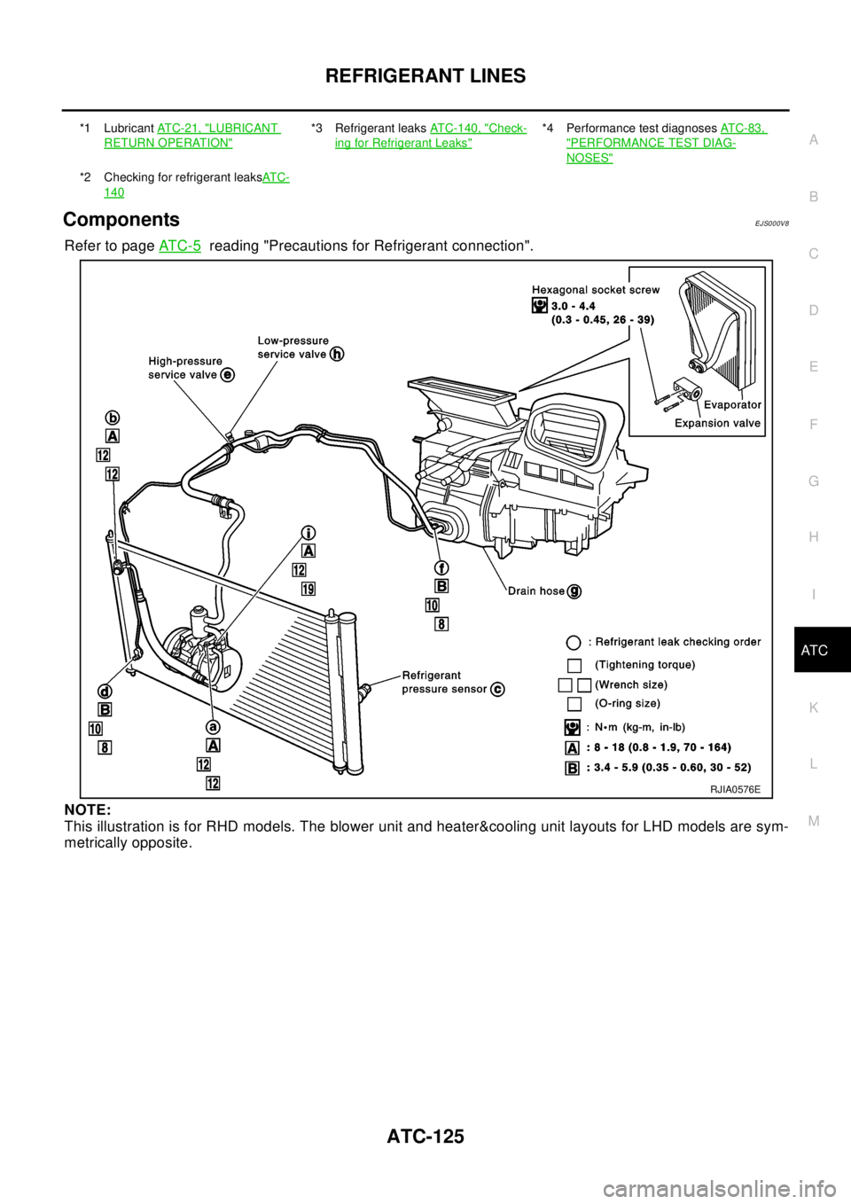
Refer to pageAT C - 5reading "Precautions for Refrigerant connection".
NOTE:
This illustration is for RHD models. The blower unit and heater&cooling unit layouts for LHD models are sym-
metrically opposite.
*1 LubricantAT C - 2 1 , "LUBRICANT
RETURN OPERATION"
*3 Refrigerant leaksATC-140, "Check-
ing for Refrigerant Leaks"
*4 Performance test diagnosesAT C - 8 3 ,
"PERFORMANCE TEST DIAG-
NOSES"
*2 Checking for refrigerant leaksAT C -
140
RJIA0576E
Page 704 of 3066
ATC-126
REFRIGERANT LINES
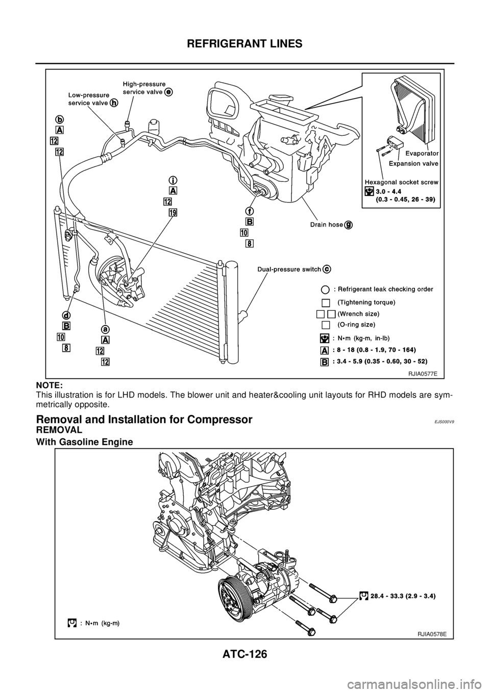
NOTE:
This illustration is for LHD models. The blower unit and heater&cooling unit layouts for RHD models are sym-
metrically opposite.
Removal and Installation for CompressorEJS000V9
REMOVAL
With Gasoline Engine
RJIA0577E
RJIA0578E
Page 717 of 3066
REFRIGERANT LINES
ATC-139
C
D
E
F
G
H
I
K
L
MA
B
AT C
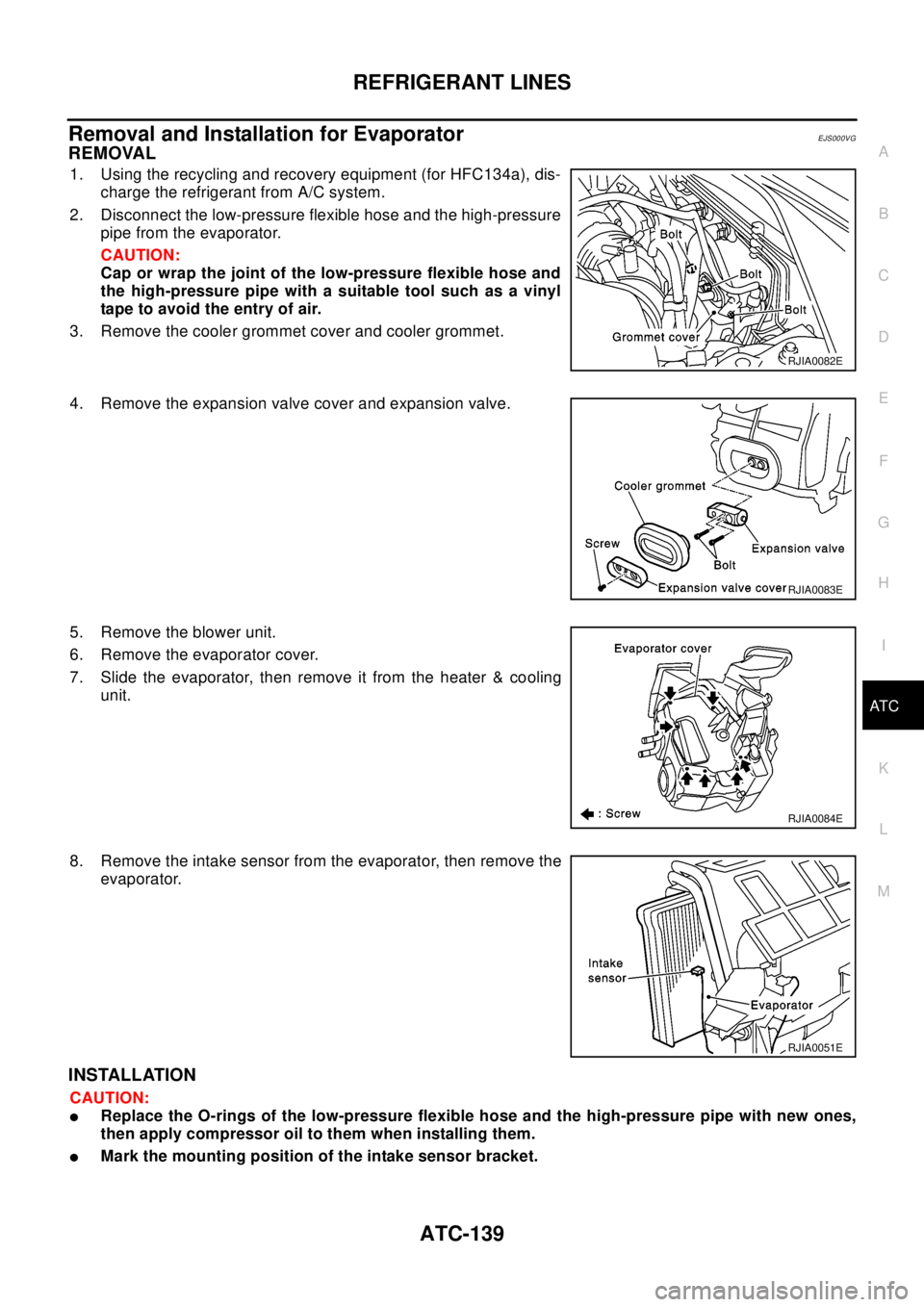
Removal and Installation for EvaporatorEJS000VG
REMOVAL
1. Using the recycling and recovery equipment (for HFC134a), dis-
charge the refrigerant from A/C system.
2. Disconnect the low-pressure flexible hose and the high-pressure
pipe from the evaporator.
CAUTION:
Cap or wrap the joint of the low-pressure flexible hose and
the high-pressure pipe with a suitable tool such as a vinyl
tape to avoid the entry of air.
3. Remove the cooler grommet cover and cooler grommet.
4. Remove the expansion valve cover and expansion valve.
5. Remove the blower unit.
6. Remove the evaporator cover.
7. Slide the evaporator, then remove it from the heater & cooling
unit.
8. Remove the intake sensor from the evaporator, then remove the
evaporator.
INSTALLATION
CAUTION:
lReplace the O-rings of the low-pressure flexible hose and the high-pressure pipe with new ones,
then apply compressor oil to them when installing them.
lMark the mounting position of the intake sensor bracket.
RJIA0082E
RJIA0083E
RJIA0084E
RJIA0051E
Page 721 of 3066
REFRIGERANT LINES
ATC-143
C
D
E
F
G
H
I
K
L
MA
B
AT C
Check all around the service valves. Ensure service valve caps are secured on the service valves (to pre-
vent leaks).
NOTE:
After removing A/C manifold gauge set from service valves, wipe any residue from valves to prevent any
false readings by leak detector.
Cooling unit (Evaporator)
With engine OFF, turn blower fan on "High" for at least 15 seconds to dissipate any refrigerant trace in the
cooling unit. Wait a minimum of 10 minutes accumulation time (refer to the manufacturer's recommended
procedure for actual wait time) before inserting the leak detector probe into the drain hose.
Keep the probe inserted for at least 10 seconds. Use caution not to contaminate the probe tip with water
or dirt that may be in the drain hose.
5. If a leak detector detects a leak, verify at least once by blowing compressed air into area of suspected
leak, then repeat check as outlined above.
6. Do not stop when one leak is found. Continue to check for additional leaks at all system components.
If no leaks are found, perform steps 7 - 10.
7. Start engine.
8. Set the heater A/C control as follows;
a. A/C switch: ON
b. Face mode
c. Intake position: Recirculation
d. Max cold temperature
e. Fan speed: High
9. Run engine at 1,500 rpm for at least 2 minutes.
10. Turn engine off and perform leak check again following steps 4 through 6 above.
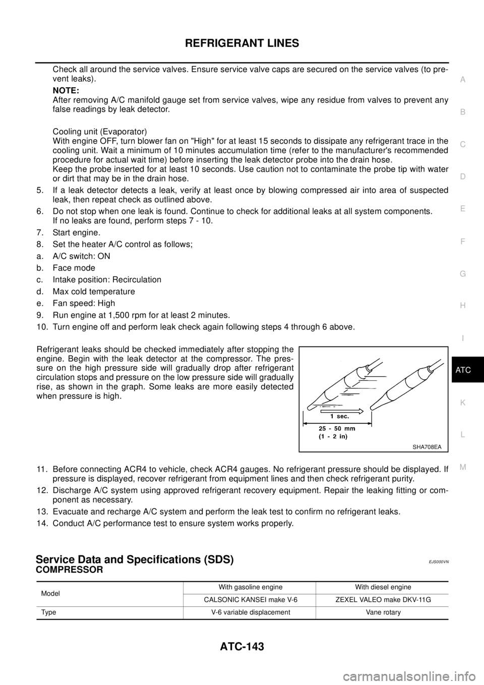
Refrigerant leaks should be checked immediately after stopping the
engine. Begin with the leak detector at the compressor. The pres-
sure on the high pressure side will gradually drop after refrigerant
circulation stops and pressure on the low pressure side will gradually
rise, as shown in the graph. Some leaks are more easily detected
when pressure is high.
11. Before connecting ACR4 to vehicle, check ACR4 gauges. No refrigerant pressure should be displayed. If
pressure is displayed, recover refrigerant from equipment lines and then check refrigerant purity.
12. Discharge A/C system using approved refrigerant recovery equipment. Repair the leaking fitting or com-
ponent as necessary.
13. Evacuate and recharge A/C system and perform the leak test to confirm no refrigerant leaks.
14. Conduct A/C performance test to ensure system works properly.
Service Data and Specifications (SDS)EJS000VN
COMPRESSOR
SHA708EA
ModelWith gasoline engine With diesel engine
CALSONIC KANSEI make V-6 ZEXEL VALEO make DKV-11G
Type V-6 variable displacement Vane rotary
Page 1020 of 3066
![NISSAN X-TRAIL 2003 Electronic User Guide CO-10
[QR20DE]
ENGINE COOLANT
2. Open drain plugs on cylinder block.
3. Remove reservoir tank and drain coolant.
4. Check drained coolant for contaminants such as rust, corrosion
or discoloration.
If](/img/5/57402/w960_57402-1019.png "NISSAN X-TRAIL 2003 Electronic User Guide CO-10
[QR20DE]
ENGINE COOLANT
2. Open drain plugs on cylinder block.
3. Remove reservoir tank and drain coolant.
4. Check drained coolant for contaminants such as rust, corrosion
or discoloration.
If")
CO-10
[QR20DE]
ENGINE COOLANT
2. Open drain plugs on cylinder block.
3. Remove reservoir tank and drain coolant.
4. Check drained coolant for contaminants such as rust, corrosion
or discoloration.
If contaminated, flush engine cooling system. Refer toCO-10,
"FLUSHING COOLING SYSTEM".
REFILLING ENGINE COOLANT
1. Install reservoir tank, radiator drain plug and cylinder block drain plug.
Apply sealant to the thread of cylinder block drain plug.
lUse Genuine Liquid Gasket or equivalent.
2. Fill radiator and reservoir tank to specified level.
lUse genuine Nissan anti-freeze coolant or equivalent mixed
with water (distilled or demineralized).
Refer toMA-17, "
RECOMMENDED FLUIDS AND LUBRI-
CANTS".
lPour coolant slowly of less than 2 (2-1/8US qt,1-3/4 lmp
qt) a minute to allow air in system to escape.
3. Warm up engine to normal operating temperature without radia-
tor cap installed.
lIf coolant overflows radiator filler hole, install filler cap.
4. Run engine at 3,000 rpm for 10 seconds and return to idle speed
with radiator cap installed.
lRepeat two or three times.
Watch coolant temperature gauge so as not to overheat the engine.
5. Stop engine and cool down to less than approximately 50°C(122°F).
lCool down using a fan to reduce the time.
lIf necessary, refill radiator up to filler neck with coolant.
6. Refill reservoir tank to MAX level line with coolant.
7. Repeat steps 5 through 7 two or more times with radiator cap installed until coolant level no longer drops.
8. Check cooling system for leaks with engine running.
9. Warm up engine, and check for sound of coolant flow while running engine from idle up to 3,000 rpm with
heater temperature controller set at several position between COOL and WARM.
lSound may be noticeable at heater unit.
10. If sound is heard, bleed air from cooling system by repeating steps 5 through 7 until coolant level no
longer drops.
lClean excess coolant from engine.
FLUSHING COOLING SYSTEM
1. Fill radiator and reservoir tank with water and reinstall radiator cap.
KBIA0163E
: 7.8 - 11.8 N·m (0.8 -1.2 kg-m , 69 - 104 in-lb)
Engine coolant capacity (With reservoir tank):
Approx. 7.1 (6-1/4 Imp qt)
SMA182B
Reservoir tank:
0.6 (1/2 lmp qt )
SMA412B
Page 1031 of 3066
![NISSAN X-TRAIL 2003 Electronic User Guide THERMOSTAT AND WATER CONTROL VALVE
CO-21
[QR20DE]
C
D
E
F
G
H
I
J
K
L
MA
CO
THERMOSTAT AND WATER CONTROL VALVEPFP:21200
Removal and InstallationEBS009SK
WA RN ING:
Never remove the radiator cap when t](/img/5/57402/w960_57402-1030.png "NISSAN X-TRAIL 2003 Electronic User Guide THERMOSTAT AND WATER CONTROL VALVE
CO-21
[QR20DE]
C
D
E
F
G
H
I
J
K
L
MA
CO
THERMOSTAT AND WATER CONTROL VALVEPFP:21200
Removal and InstallationEBS009SK
WA RN ING:
Never remove the radiator cap when t")
THERMOSTAT AND WATER CONTROL VALVE
CO-21
[QR20DE]
C
D
E
F
G
H
I
J
K
L
MA
CO
THERMOSTAT AND WATER CONTROL VALVEPFP:21200
Removal and InstallationEBS009SK
WA RN ING:
Never remove the radiator cap when the engine is hot. Serious burns could occur from high pressure
coolant escaping from the radiator.
REMOVAL
Thermostat Removal
1. Drain engine coolant. Refer toCO-9, "DRAINING ENGINE COOLANT".
CAUTION:
Perform when the engine cold.
2. Disconnect radiator lower hose at water inlet side.
3. Remove water inlet and thermostat.
Water Control Valve Removal
1. Drain engine coolant. Refer toCO-9, "DRAINING ENGINE COOLANT".
2. Disconnect upper radiator hose, heater pipe and heater hose at water outlet side.
3. Remove water outlet.
4. Remove water control valve.
PBIC0239E
1 Thermostat 2 Water inlet 3 Water control valve
4 Water outlet 5 Heater hose 6 Engine coolant temperature sensor
7Heaterpipe
Page 1032 of 3066
![NISSAN X-TRAIL 2003 Electronic User Guide CO-22
[QR20DE]
THERMOSTAT AND WATER CONTROL VALVE
INSPECTION AFTER REMOVAL
lPlace a string so that it is caught in the valves of the thermostat
and water control valve. Immerse fully in a container fi](/img/5/57402/w960_57402-1031.png "NISSAN X-TRAIL 2003 Electronic User Guide CO-22
[QR20DE]
THERMOSTAT AND WATER CONTROL VALVE
INSPECTION AFTER REMOVAL
lPlace a string so that it is caught in the valves of the thermostat
and water control valve. Immerse fully in a container fi")
CO-22
[QR20DE]
THERMOSTAT AND WATER CONTROL VALVE
INSPECTION AFTER REMOVAL
lPlace a string so that it is caught in the valves of the thermostat
and water control valve. Immerse fully in a container filled with
water. Heat while stirring. (The example in the figure shows the
thermostat.)
lThe valve opening temperature is the temperature at which the
valve opens and the falls from the thread.
lContinue heating. Check the full-open lift amount.
NOTE:
The full-open lift amount standard temperature for the water
control valve is the reference value.
lAfter checking the full-open lift amount, lower the water temper-
ature and check the valve closing temperature.
Standard values
INSTALLATION
lInstall in the reverse order of removal paying attention to the following.
Installation of Thermostat and Water Control Valve
lInstall the thermostat and water control valve with the whole cir-
cumference of each flange part fit securely inside the rubber
ring. (The example in the figure shows the thermostat.)
lInstall the thermostat with the jiggle valve facing upwards. (The
position deviation may be within the range of±10°)
lInstall the water control valve with the up-mark facing up and the
frame center part facing upwards. (The position deviation may
be within the range of±10°)
Heater Pipe Installation
lFirst apply a neutral detergent to the O-ring, then quickly insert the insertion parts of the heater pipe into
the installation holes.
SLC252B
Thermostat Water control valve
Valve opening temperature 80.5 - 83.5°C(177-182°F) 93.5 - 96.5°C (200 - 206°F)
Full-open lift amountMore than 8 mm/ 95°C
(0.315 in/ 203°F)More than 8 mm/ 108°C
(0.315 in/ 226°F)
Valve closing temperature 77°C(171°F) 90°C (194°F)
PBIC0157E
PBIC0158E
Page 1042 of 3066
![NISSAN X-TRAIL 2003 Electronic User Guide CO-32
[YD22DDTi]
ENGINE COOLANT
3. Fill reservoir tank to specified level.
4. Warm up engine to normal operating temperature without radia-
tor cap installed.
lIf coolant overflows radiator filler hol](/img/5/57402/w960_57402-1041.png "NISSAN X-TRAIL 2003 Electronic User Guide CO-32
[YD22DDTi]
ENGINE COOLANT
3. Fill reservoir tank to specified level.
4. Warm up engine to normal operating temperature without radia-
tor cap installed.
lIf coolant overflows radiator filler hol")
CO-32
[YD22DDTi]
ENGINE COOLANT
3. Fill reservoir tank to specified level.
4. Warm up engine to normal operating temperature without radia-
tor cap installed.
lIf coolant overflows radiator filler hole, install filler cap.
5. Run engine at 3,000 rpm for 10 seconds and return to idle speed
with radiator cap installed.
lRepeat two or three times.
Watch coolant temperature gauge so as not to overheat the
engine.
6. Stop engine and cool down to less than approximately
50°C(122°F).
lCool down using a fan to reduce the time.
lIf necessary, refill radiator up to filler neck with coolant.
7. Refill reservoir tank to MAX level line with coolant.
8. Repeat steps 5 through 7 two or more times with radiator cap installed until coolant level no longer drops.
9. Check cooling system for leaks with engine running.
10. Warm up engine, and check for sound of coolant flow while running engine from idle up to 3,000 rpm with
heater temperature controller set at several position between COOL and WARM.
lSound may be noticeable at heater unit.
11. If sound is heard, bleed air from cooling system by repeating steps 5 through 7 until coolant level no
longer drops.
lClean excess coolant from engine.
FLUSHING COOLING SYSTEM
1. Fill radiator with water until water spills from the air relief hole, then close air relief flag. Fill radiator and
reservoir tank with water and reinstall radiator cap.
2. Run engine and warm it up to normal operating temperature.
3. Rev engine two or three times under no-load.
4. Stop engine and wait until it cools down.
5. Drain water.
6. Repeat steps 1 through 5 until clear water begins to drain from radiator.
SMA412B
Page 1052 of 3066
![NISSAN X-TRAIL 2003 Electronic User Guide CO-42
[YD22DDTi]
THERMOSTAT AND WATER PIPING
THERMOSTAT AND WATER PIPING
PFP:21200
Removal and InstallationEBS00BK9
WAR NIN G:
Never remove the radiator cap when the engine is hot. Serious burns could](/img/5/57402/w960_57402-1051.png "NISSAN X-TRAIL 2003 Electronic User Guide CO-42
[YD22DDTi]
THERMOSTAT AND WATER PIPING
THERMOSTAT AND WATER PIPING
PFP:21200
Removal and InstallationEBS00BK9
WAR NIN G:
Never remove the radiator cap when the engine is hot. Serious burns could")
CO-42
[YD22DDTi]
THERMOSTAT AND WATER PIPING
THERMOSTAT AND WATER PIPING
PFP:21200
Removal and InstallationEBS00BK9
WAR NIN G:
Never remove the radiator cap when the engine is hot. Serious burns could occur from high pressure
coolant escaping from the radiator.
REMOVAL
1. Remove the under cover and splash cover (right and left).
2. Drain engine coolant. Refer toCO-30, "
DRAINING ENGINE COOLANT".
CAUTION:
Perform when the engine cold.
3. Remove radiator lower hose from water inlet side.
4. Remove water inlet and thermostat.
5. Remove thermostat housing.
SBIA0133E
1 Thermostat 2 Water inlet 3 Thermostat housing
4 Water inlet pipe 5 Heater return pipe 6 Gasket
Page 1053 of 3066
![NISSAN X-TRAIL 2003 Electronic User Guide THERMOSTAT AND WATER PIPING
CO-43
[YD22DDTi]
C
D
E
F
G
H
I
J
K
L
MA
CO
INSPECTION AFTER REMOVAL
Thermostat
lPlace a string so that it is caught in the valves of the thermostat.
Immerse fully in a cont](/img/5/57402/w960_57402-1052.png "NISSAN X-TRAIL 2003 Electronic User Guide THERMOSTAT AND WATER PIPING
CO-43
[YD22DDTi]
C
D
E
F
G
H
I
J
K
L
MA
CO
INSPECTION AFTER REMOVAL
Thermostat
lPlace a string so that it is caught in the valves of the thermostat.
Immerse fully in a cont")
THERMOSTAT AND WATER PIPING
CO-43
[YD22DDTi]
C
D
E
F
G
H
I
J
K
L
MA
CO
INSPECTION AFTER REMOVAL
Thermostat
lPlace a string so that it is caught in the valves of the thermostat.
Immerse fully in a container filled with water. Heat while stirring.
lThe valve opening temperature is the temperature at which the
valve opens and falls from the thread.
lContinue heating. Check the full-open lift amount.
lAfter checking the full-open lift amount, lower the water temper-
ature and check the valve closing temperature.
Standard values
INSTALLATION
lInstall in the reverse order of removal paying attention to the following.
Thermostat
lInstall the thermostat with the whole circumference of each
flange part fit securely inside the rubber ring.
lInstall the thermostat with the jiggle valve facing upwards.
Heater Pipe
lFirst apply a neutral detergent to the O-ring, then quickly insert the insertion parts of the heater pipe into
the installation holes.
SLC252B
Item Thermostat
Valve opening temperature 80 - 84°C (176 - 183°F)
Full-open lift amount More than 10 mm/ 95°C (0.39 in/ 203°F)
Valve closing temperature Approximatery 77°C (171°F)
JLC300B