torque NISSAN X-TRAIL 2003 Electronic Repair Manual
[x] Cancel search | Manufacturer: NISSAN, Model Year: 2003, Model line: X-TRAIL, Model: NISSAN X-TRAIL 2003Pages: 3066, PDF Size: 51.47 MB
Page 3 of 3066

ACC-1
ACCELERATOR CONTROL SYSTEM
B ENGINE
CONTENTS
C
D
E
F
G
H
I
J
K
L
M
SECTION
A
ACC
ACCELERATOR CONTROL SYSTEM
ACCELERATOR CONTROL SYSTEM ...................... 2
Removal and Installation .......................................... 2
QR20DE ................................................................ 2
YD22DDTI ............................................................. 2
REMOVAL ............................................................. 2
INSTALLATION ..................................................... 3
INSPECTION AFTER INSTALLATION ................. 3SERVICE DATA AND SPECIFICATIONS (SDS) ........ 4
Tightening Torque ..................................................... 4
Page 6 of 3066

ACC-4
SERVICE DATA AND SPECIFICATIONS (SDS)
SERVICE DATA AND SPECIFICATIONS (SDS)
PFP:00030
Tightening TorqueEBS003CI
Unit: N·m (Kg-m, in-lb)
Accelerator pedal assembly 4.3 - 5.9 (0.44 - 0.60, 39 - 52)
Accelerator pedal assembly (work unit) (YD22DDTi) 4.3 - 5.9 (0.44 - 0.60, 39 - 52)
Accelerator pedal bracket (YD22DDTi) 4.3 - 5.9 (0.44 - 0.60, 39 - 52)
Page 8 of 3066

AT-2
DTC P0732 A/T 2ND GEAR FUNCTION ................158
Description ............................................................158
Wiring Diagram — AT — 2ND ..............................161
Diagnostic Procedure ...........................................162
Component Inspection ..........................................163
DTC P0733 A/T 3RD GEAR FUNCTION ................165
Description ............................................................165
Wiring Diagram — AT — 3RD ..............................168
Diagnostic Procedure ...........................................169
Component Inspection ..........................................170
DTC P0734 A/T 4TH GEAR FUNCTION ................172
Description ............................................................172
Wiring Diagram — AT — 4TH ...............................175
Diagnostic Procedure ...........................................176
Component Inspection ..........................................179
DTC P0740 TORQUE CONVERTER CLUTCH
SOLENOID VALVE .................................................181
Description ............................................................181
Wiring Diagram — AT — TCV ..............................183
Diagnostic Procedure ...........................................184
Component Inspection ..........................................185
DTC P0745 LINE PRESSURE SOLENOID VALVE. 186
Description ............................................................186
Wiring Diagram — AT — LPSV ............................188
Diagnostic Procedure ...........................................189
Component Inspection ..........................................191
DTC P0750 SHIFT SOLENOID VALVE A ...............193
Description ............................................................193
Wiring Diagram — AT — SSV/A ...........................195
Diagnostic Procedure ...........................................196
Component Inspection ..........................................197
DTC P0755 SHIFT SOLENOID VALVE B ...............198
Description ............................................................198
Wiring Diagram — AT — SSV/B ...........................200
Diagnostic Procedure ...........................................201
Component Inspection ..........................................202
DTC P1705 ACCELERATOR PEDAL POSITION
(APP) SENSOR .......................................................203
Description ............................................................203
Wiring Diagram — AT — TPS ..............................205
Diagnostic Procedure ...........................................206
DTC P1760 OVERRUN CLUTCH SOLENOID
VALVE .....................................................................208
Description ............................................................208
Wiring Diagram — AT — OVRCSV ......................210
Diagnostic Procedure ...........................................211
Component Inspection ..........................................212
DTC U1000 CAN COMMUNICATION LINE ............213
Description ............................................................213
On Board Diagnosis Logic ....................................213
..............................................................................213
Wiring Diagram — AT ...........................................214
Diagnostic Procedure ...........................................215
DTC BATT/FLUID TEMP SEN (A/T FLUID TEMP
SENSOR CIRCUIT AND TCM POWER SOURCE). 216
Description ............................................................216
Wiring Diagram — AT — BA/FTS .........................218Diagnostic Procedure ............................................ 219
Component Inspection .......................................... 221
DTC VEHICLE SPEED SENSOR MTR ................... 222
Description ............................................................ 222
Wiring Diagram — AT — VSSMTR ....................... 224
Diagnostic Procedure ............................................ 225
DTC CONTROL UNIT (RAM), CONTROL UNIT
(ROM) ...................................................................... 226
Description ............................................................ 226
Diagnostic Procedure ............................................ 227
DTC CONTROL UNIT(EEPROM) ........................... 228
Description ............................................................ 228
Diagnostic Procedure ............................................ 229
TROUBLE DIAGNOSES FOR SYMPTOMS ........... 230
.............................................................................. 230
1. O/D OFF Indicator Lamp Does Not Come On .. 232
2. Engine Cannot Be Started In “P” and “N” Position. 233
3. In “P” Position, Vehicle Moves Forward Or Back-
ward When Pushed ............................................... 234
4. In “N” Position, Vehicle Moves .......................... 234
5. Large Shock. “N”®“R” Position ...................... 236
6. Vehicle Does Not Creep Backward In “R” Position. 237
7. Vehicle Does Not Creep Forward In “D”, “2” Or
“1” Position ............................................................ 240
8. Vehicle Cannot Be Started From D
1................. 242
9. A/T Does Not Shift: D
1®D2Or Does Not Kick-
down: D
4®D2..................................................... 244
10. A/T Does Not Shift: D
2®D3.......................... 246
11.A/TDoesNotShift:D
3®D4........................... 249
12. A/T Does Not Perform Lock-up ....................... 252
13. A/T Does Not Hold Lock-up Condition ............ 253
14. Lock-up Is Not Released ................................. 254
15. Engine Speed Does Not Return To Idle (Light
Braking D
4®D3) ................................................. 255
16. Vehicle Does Not Start From D
1..................... 257
17. A/T Does Not Shift: D
4®D3, When Overdrive
Control Switch “ON”®“OFF” ............................... 258
18. A/T Does Not Shift: D
3®22, When Selector
Lever “D”®“2” Position ....................................... 258
19. A/T Does Not Shift: 2
2®11, When Selector
Lever “2”®“1” Position ........................................ 259
20. Vehicle Does Not Decelerate By Engine Brake. 259
21. TCM Self-diagnosis Does Not Activate (PNP &
Overdrive Control Switches, and Throttle Position
Sensor Circuit Checks) ......................................... 260
EXC.F/EURO-OBD
ON BOARD DIAGNOSTIC SYSTEM DESCRIP-
TION ........................................................................ 267
CONSULT-II .......................................................... 267
Diagnostic Procedure Without CONSULT-II ......... 273
TROUBLE DIAGNOSIS — INTRODUCTION ......... 279
Introduction ........................................................... 279
Work Flow ............................................................. 284
TROUBLE DIAGNOSIS — BASIC INSPECTION ... 286
A/T Fluid Check .................................................... 286
Stall Test ................................................................ 287
Page 9 of 3066

AT-3
D
E
F
G
H
I
J
K
L
MA
B
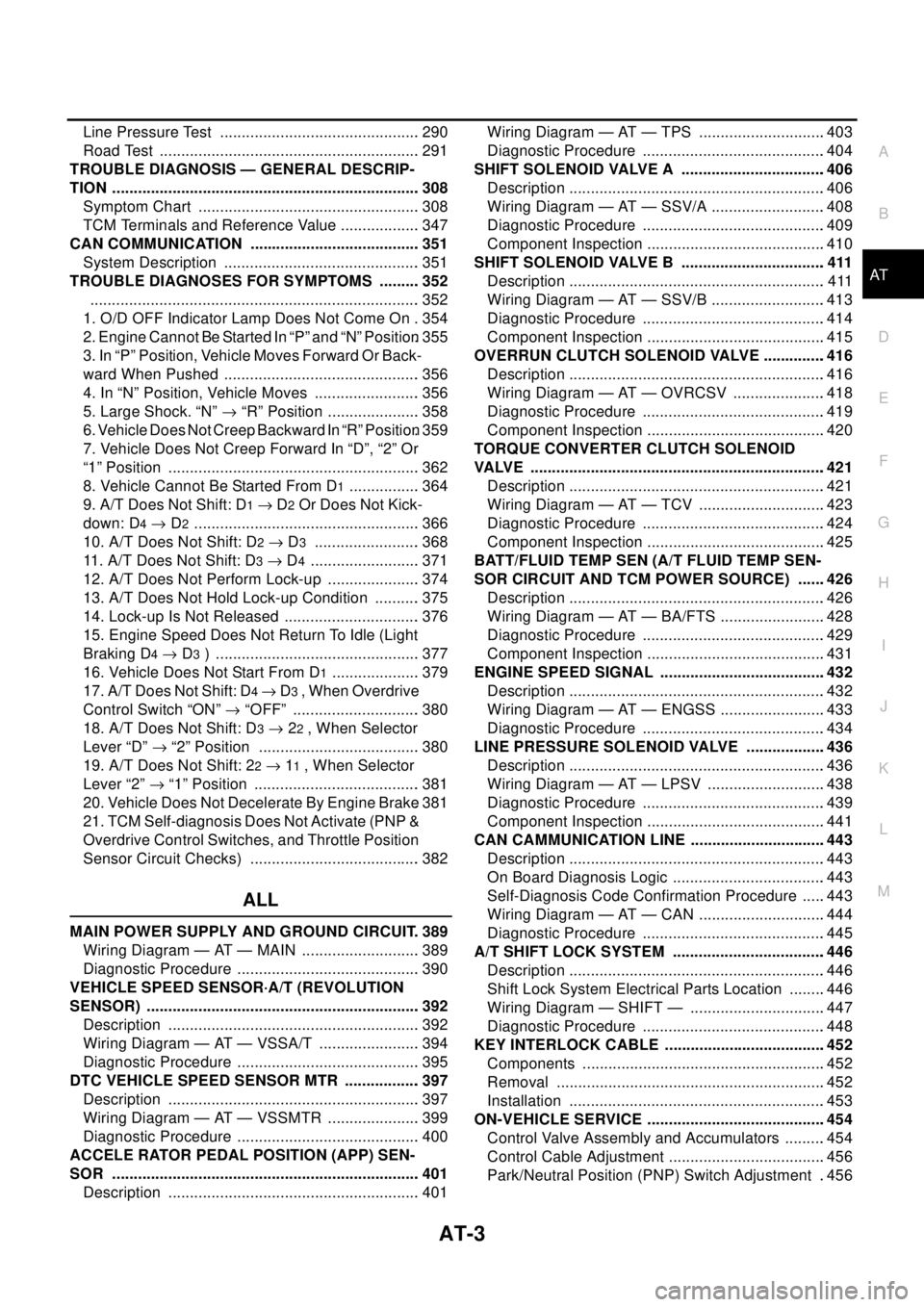
AT Line Pressure Test ............................................... 290
Road Test ............................................................. 291
TROUBLE DIAGNOSIS — GENERAL DESCRIP-
TION ........................................................................ 308
Symptom Chart .................................................... 308
TCM Terminals and Reference Value ................... 347
CAN COMMUNICATION ........................................ 351
System Description .............................................. 351
TROUBLE DIAGNOSES FOR SYMPTOMS .......... 352
............................................................................. 352
1. O/D OFF Indicator Lamp Does Not Come On . 354
2. Engine Cannot Be Started In “P” and “N” Position. 355
3. In “P” Position, Vehicle Moves Forward Or Back-
ward When Pushed .............................................. 356
4. In “N” Position, Vehicle Moves ......................... 356
5. Large Shock. “N”®“R” Position ...................... 358
6. Vehicle Does Not Creep Backward In “R” Position. 359
7. Vehicle Does Not Creep Forward In “D”, “2” Or
“1” Position ........................................................... 362
8. Vehicle Cannot Be Started From D
1................. 364
9. A/T Does Not Shift: D
1®D2Or Does Not Kick-
down: D
4®D2..................................................... 366
10. A/T Does Not Shift: D
2®D3......................... 368
11.A/TDoesNotShift:D
3®D4.......................... 371
12. A/T Does Not Perform Lock-up ...................... 374
13. A/T Does Not Hold Lock-up Condition ........... 375
14. Lock-up Is Not Released ................................ 376
15. Engine Speed Does Not Return To Idle (Light
Braking D
4®D3) ................................................ 377
16. Vehicle Does Not Start From D
1..................... 379
17. A/T Does Not Shift: D
4®D3, When Overdrive
Control Switch “ON”®“OFF” .............................. 380
18. A/T Does Not Shift: D
3®22, When Selector
Lever “D”®“2” Position ...................................... 380
19. A/T Does Not Shift: 2
2®11, When Selector
Lever “2”®“1” Position ....................................... 381
20. Vehicle Does Not Decelerate By Engine Brake. 381
21. TCM Self-diagnosis Does Not Activate (PNP &
Overdrive Control Switches, and Throttle Position
Sensor Circuit Checks) ........................................ 382
ALL
MAIN POWER SUPPLY AND GROUND CIRCUIT. 389
Wiring Diagram — AT — MAIN ............................ 389
Diagnostic Procedure ........................................... 390
VEHICLE SPEED SENSOR·A/T (REVOLUTION
SENSOR) ................................................................ 392
Description ........................................................... 392
Wiring Diagram — AT — VSSA/T ........................ 394
Diagnostic Procedure ........................................... 395
DTC VEHICLE SPEED SENSOR MTR .................. 397
Description ........................................................... 397
Wiring Diagram — AT — VSSMTR ...................... 399
Diagnostic Procedure ........................................... 400
ACCELE RATOR PEDAL POSITION (APP) SEN-
SOR ........................................................................ 401
Description ........................................................... 401Wiring Diagram — AT — TPS ..............................403
Diagnostic Procedure ...........................................404
SHIFT SOLENOID VALVE A ..................................406
Description ............................................................406
Wiring Diagram — AT — SSV/A ...........................408
Diagnostic Procedure ...........................................409
Component Inspection ..........................................410
SHIFT SOLENOID VALVE B ..................................411
Description ............................................................411
Wiring Diagram — AT — SSV/B ...........................413
Diagnostic Procedure ...........................................414
Component Inspection ..........................................415
OVERRUN CLUTCH SOLENOID VALVE ...............416
Description ............................................................416
Wiring Diagram — AT — OVRCSV ......................418
Diagnostic Procedure ...........................................419
Component Inspection ..........................................420
TORQUE CONVERTER CLUTCH SOLENOID
VALVE .....................................................................421
Description ............................................................421
Wiring Diagram — AT — TCV ..............................423
Diagnostic Procedure ...........................................424
Component Inspection ..........................................425
BATT/FLUID TEMP SEN (A/T FLUID TEMP SEN-
SOR CIRCUIT AND TCM POWER SOURCE) .......426
Description ............................................................426
Wiring Diagram — AT — BA/FTS .........................428
Diagnostic Procedure ...........................................429
Component Inspection ..........................................431
ENGINE SPEED SIGNAL .......................................432
Description ............................................................432
Wiring Diagram — AT — ENGSS .........................433
Diagnostic Procedure ...........................................434
LINE PRESSURE SOLENOID VALVE ...................436
Description ............................................................436
Wiring Diagram — AT — LPSV ............................438
Diagnostic Procedure ...........................................439
Component Inspection ..........................................441
CAN CAMMUNICATION LINE ................................443
Description ............................................................443
On Board Diagnosis Logic ....................................443
Self-Diagnosis Code Confirmation Procedure ......443
Wiring Diagram — AT — CAN ..............................444
Diagnostic Procedure ...........................................445
A/T SHIFT LOCK SYSTEM ....................................446
Description ............................................................446
Shift Lock System Electrical Parts Location .........446
Wiring Diagram — SHIFT — ................................447
Diagnostic Procedure ...........................................448
KEY INTERLOCK CABLE ......................................452
Components .........................................................452
Removal ...............................................................452
Installation ............................................................453
ON-VEHICLE SERVICE ..........................................454
Control Valve Assembly and Accumulators ..........454
Control Cable Adjustment .....................................456
Park/Neutral Position (PNP) Switch Adjustment ..456
Page 13 of 3066

PRECAUTIONS
AT-7
D
E
F
G
H
I
J
K
L
MA
B
AT
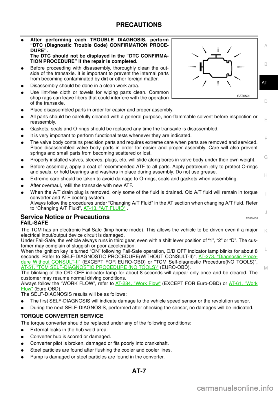
lAfter performing each TROUBLE DIAGNOSIS, perform
“DTC (Diagnostic Trouble Code) CONFIRMATION PROCE-
DURE”.
The DTC should not be displayed in the “DTC CONFIRMA-
TION PROCEDURE” if the repair is completed.
lBefore proceeding with disassembly, thoroughly clean the out-
side of the transaxle. It is important to prevent the internal parts
from becoming contaminated by dirt or other foreign matter.
lDisassembly should be done in a clean work area.
lUse lint-free cloth or towels for wiping parts clean. Common
shop rags can leave fibers that could interfere with the operation
of the transaxle.
lPlace disassembled parts in order for easier and proper assembly.
lAll parts should be carefully cleaned with a general purpose, non-flammable solvent before inspection or
reassembly.
lGaskets, seals and O-rings should be replaced any time the transaxle is disassembled.
lIt is very important to perform functional tests whenever they are indicated.
lThe valve body contains precision parts and requires extreme care when parts are removed and serviced.
Place disassembled valve body parts in order for easier and proper assembly. Care will also prevent
springs and small parts from becoming scattered or lost.
lProperly installed valves, sleeves, plugs, etc. will slide along bores in valve body under their own weight.
lBefore assembly, apply a coat of recommended ATF to all parts. Apply petroleum jelly to protect O-rings
and seals, or hold bearings and washers in place during assembly. Do not use grease.
lExtreme care should be taken to avoid damage to O-rings, seals and gaskets when assembling.
lAfter overhaul, refill the transaxle with new ATF.
lWhen the A/T drain plug is removed, only some of the fluid is drained. Old A/T fluid will remain in torque
converter and ATF cooling system.
Always follow the procedures under “Changing A/T Fluid” in the AT section when changing A/T fluid. Refer
to “Changing A/T Fluid”,AT-13, "
A/T FLUID".
Service Notice or PrecautionsECS004Q3
FAI L-S AFE
The TCM has an electronic Fail-Safe (limp home mode). This allows the vehicle to be driven even if a major
electrical input/output device circuit is damaged.
Under Fail-Safe, the vehicle always runs in third gear, even with a shift lever position of “1”, “2” or “D”. The cus-
tomer may complain of sluggish or poor acceleration.
When the ignition key is turned “ON” following Fail-Safe operation, O/D OFF indicator lamp blinks for about 8
seconds. Refer to SELF-DIAGNOSTIC PROCEDURE(WITHOUT CONSULT-II)",AT- 2 7 3 , "
Diagnostic Proce-
dure Without CONSULT-II"(EXCEPT FOR EURO-OBD) or "TCM Self-diagnostic Procedure(NO TOOLS)",
AT- 5 1 , "
TCM SELF-DIAGNOSTIC PROCEDURE (NO TOOLS)"(EURO-OBD).
The blinking of the O/D OFF indicator lamp for about 8 seconds will appear only once and be cleared. The
customer may resume normal driving conditions.
Always follow the “WORK FLOW”, refer toAT-284, "
Work Flow"(EXCEPT FOR Euro-OBD) orAT-61, "Work
Flow"(Euro-OBD).
The SELF-DIAGNOSIS results will be as follows:
lThe first SELF-DIAGNOSIS will indicate damage to the vehicle speed sensor or the revolution sensor.
lDuring the next SELF-DIAGNOSIS, performed after checking the sensor, no damages will be indicated.
TORQUE CONVERTER SERVICE
The torque converter should be replaced under any of the following conditions:
lExternal leaks in the hub weld area.
lConverter hub is scored or damaged.
lConverter pilot is broken, damaged or fits poorly into crankshaft.
lSteel particles are found after flushing the cooler and cooler lines.
lPump is damaged or steel particles are found in the converter.
SAT652J
Page 14 of 3066

AT-8
PRECAUTIONS
lVehicle has TCC shudder and/or no TCC apply. Replace only after all hydraulic and electrical diagnoses
have been made. (Converter clutch material may be glazed.)
lConverter is contaminated with engine coolant containing antifreeze.
lInternal failure of stator roller clutch.
lHeavy clutch debris due to overheating (blue converter).
lSteel particles or clutch lining material found in fluid filter or on magnet when no internal parts in unit are
worn or damaged — indicates that lining material came from converter.
The torque converter should not be replaced if:
lThe fluid has an odor, is discolored, and there is no evidence of metal or clutch facing particles.
lThe threads in one or more of the converter bolt holes are damaged.
lTransaxle failure did not display evidence of damaged or worn internal parts, steel particles or clutch plate
lining material in unit and inside the fluid filter.
lVehicle has been exposed to high mileage (only). The exception may be where the torque converter
clutch dampener plate lining has seen excess wear by vehicles operated in heavy and/or constant traffic,
such as taxi, delivery or police use.
EURO-OBD SELF-DIAGNOSIS — EURO-OBD —
lA/T self-diagnosis is performed by the TCM in combination with the ECM. The results can be read through
the blinking pattern of the O/D OFF indicator lamp or the malfunction indicator lamp (MIL). Refer to the
table onAT-42, "
SELF-DIAGNOSTIC RESULT TEST MODE"for the indicator used to display each self-
diagnostic result.
lThe self-diagnostic results indicated by the MIL are automatically stored in both the ECM and TCM mem-
ories.
Always perform the procedure “HOW TO ERASE DTC” onAT-39, "
HOW TO ERASE DTC"to com-
plete the repair and avoid unnecessary blinking of the MIL.
lThe following self-diagnostic items can be detected using ECM self-diagnostic results mode* only when
the O/D OFF indicator lamp does not indicate any malfunctions.
–PNP switch
–A/T 1st, 2nd, 3rd, or 4th gear function
*: For details of EURO-OBD, refer toAT - 3 7 , "
ON BOARD DIAGNOSTIC SYSTEM DESCRIPTION".
lCertain systems and components, especially those related to EURO-OBD, may use a new style
slide-locking type harness connector.
For description and how to disconnect, refer toPG-70, "
HARNESS CONNECTOR".
Wiring Diagrams and Trouble DiagnosisECS004Q4
When you read wiring diagrams, refer to the following:
lGI-14, "How to Read Wiring Diagrams".
lPG-2, "POWER SUPPLY ROUTING".
When you perform trouble diagnosis, refer to the following:
lGI-11, "HOW TO FOLLOW TEST GROUPS IN TROUBLE DIAGNOSES".
l"", “HOW TO PERFORM EFFICIENT DIAGNOSIS FOR AN ELECTRICAL INCIDENT”
Page 19 of 3066

A/T FLUID
AT-13
D
E
F
G
H
I
J
K
L
MA
B
AT
A/T FLUIDPFP:KLE40
Checking A/T FluidECS004Q7
1. Warm up engine.
2. Check for fluid leakage.
3. Before driving, fluid level can be checked at fluid temperatures
of 30 to 50°C (86 to 122°F) using “COLD” range on dipstick.
a. Park vehicle on level surface and set parking brake.
b. Start engine and move selector lever through each gear posi-
tion. Leave selector lever in “P” position.
c. Check fluid level with engine idling.
d. Remove dipstick and note reading. If level is at low side of either
range, and fluid to the charging pipe.
e. Re-insert dipstick into charging pipe as far as it will go.
f. Remove dipstick and note reading. If reading is at low side of range, add fluid to the charging pipe.
Do not overfill.
4. Drive vehicle for approximately 5 minutes in urban areas.
5. Re-check fluid level at fluid temperatures of 50 to 80°C (122 to 176°F) using “HOT” range on dipstick.
6. Check fluid condition.
lIf fluid is very dark or smells burned, refer to AT section for
checking operation of A/T. Flush cooling system after repair of
A/T.
lIf A/T fluid contains frictional material (clutches, bands, etc.),
replace radiator and flush cooler line using cleaning solvent
and compressed air after repair of A/T. Refer toCO-12,
"RADIATOR",CO-15, "RADIATOR (ALUMINUM TYPE)",,.
Changing A/T FluidECS004Q8
1. Warm up A/T fluid.
2. Stop engine.
3. Drain A/T fluid from drain plug and refill with new A/T fluid.
Always refill same volume with drained fluid.
4. Run engine at idle speed for five minutes.
5. Check fluid level and condition. Refer to “Checking A/T Fluid”. If fluid is still dirty, repeat steps 2 through 5.
SMA827CA
SMA853B
Fluid grade:
Genuine Nissan ATF or equivalent. Refer toMA-
17, "RECOMMENDED FLUIDS AND LUBRI-
CANTS".
Fluid capacity (With torque converter):
Approx. 8.0 (7.01 lmp qt)
Drain plug:
:29-39N·m(3.0-4.0kg-m,22-29ft-lb)
SMA027D
Page 23 of 3066

OVERALL SYSTEM
AT-17
D
E
F
G
H
I
J
K
L
MA
B
AT
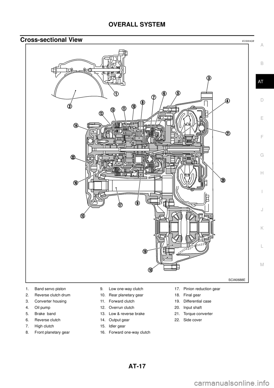
Cross-sectional ViewECS004QB
SCIA0688E
1. Band servo piston 9. Low one-way clutch 17. Pinion reduction gear
2. Reverse clutch drum 10. Rear planetary gear 18. Final gear
3. Converter housing 11. Forward clutch 19. Differential case
4. Oil pump 12. Overrun clutch 20. Input shaft
5. Brake band 13. Low & reverse brake 21. Torque converter
6. Reverse clutch 14. Output gear 22. Side cover
7. High clutch 15. Idler gear
8. Front planetary gear 16. Forward one-way clutch
Page 25 of 3066

OVERALL SYSTEM
AT-19
D
E
F
G
H
I
J
K
L
MA
B
AT
Shift MechanismECS004QD
CONSTRUCTION
FUNCTION OF CLUTCH AND BRAKE
CLUTCH AND BAND CHART
1. Torque converter 2. Oil pump 3. Input shaft
4. Brake band 5. Reverse clutch 6. High clutch
7. Front sun gear 8. Front pinion gear 9. Front internal gear
10. Front planetary carrier 11. Rear sun gear 12. Rear pinion gear
13. Rear internal gear 14. Rear planetary carrier 15. Forward clutch
16. Forward one-way clutch 17. Overrun clutch 18. Low one-way clutch
19. Low & reverse brake 20. Parking pawl 21. Parking gear
22. Output shaft 23. Idle gear 24. Output gear
SAT998I
Clutch and brake components Abbr. Function
5Reverse clutch R/C To transmit input power to front sun gear7.
6High clutch H/C To transmit input power to front planetary carrier10.
15Forward clutch F/C To connect front planetary carrier10with forward one-way clutch16.
17Overrun clutch O/C To connect front planetary carrier10with rear internal gear13.
4Brake band B/B To lock front sun gear7.
16Forward one-way clutch F/O.C When forward clutch15is engaged, to stop rear internal gear13from rotating in
opposite direction against engine revolution.
18Low one-way clutch L/O.C To stop front planetary carrier10from rotating in opposite direction against
engine revolution.
19Low & reverse brake L & R/B To lock front planetary carrier10.
Shift positionRever
se
clutch
5High
clutch
6For-
ward
clutch
15Over-
run
clutch
17Band servo
Forward
one-way
clutch
16Low
one-
way
clutch
18Low &
revers
e
brake
19Lock-
upRemarks
2nd
apply3rd
releas
e4th
apply
PPA R K
POSITION
RREVERSE
POSITION
Page 33 of 3066

OVERALL SYSTEM
AT-27
D
E
F
G
H
I
J
K
L
MA
B
AT
Control SystemECS004QE
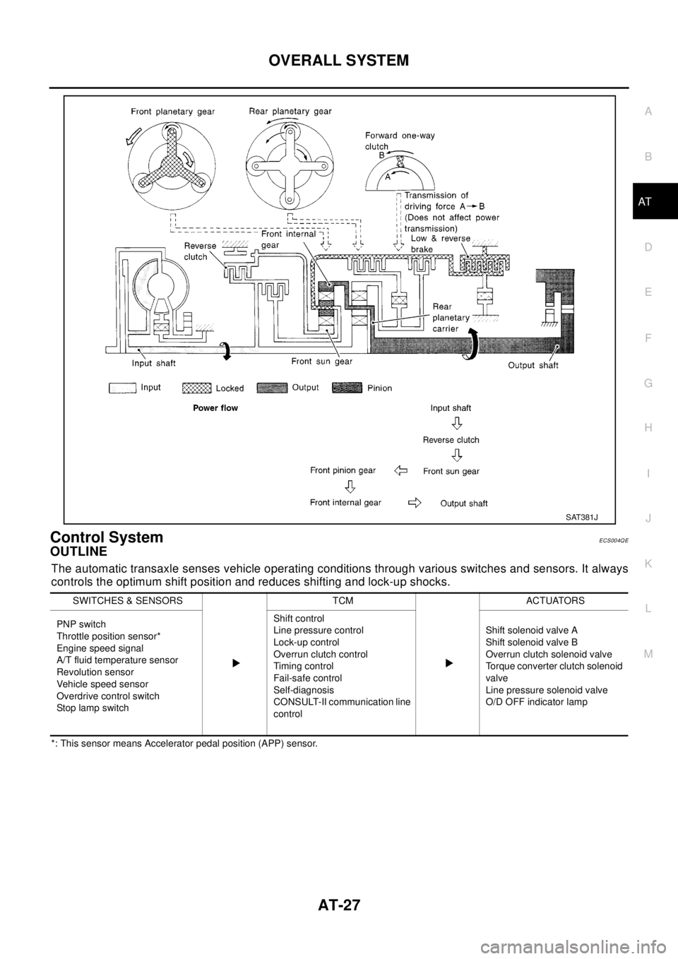
OUTLINE
The automatic transaxle senses vehicle operating conditions through various switches and sensors. It always
controls the optimum shift position and reduces shifting and lock-up shocks.
*: This sensor means Accelerator pedal position (APP) sensor.
SAT381J
SWITCHES & SENSORS TCM ACTUATORS
PNP switch
Throttle position sensor*
Engine speed signal
A/T fluid temperature sensor
Revolution sensor
Vehicle speed sensor
Overdrive control switch
Stop la mp s witchShift control
Line pressure control
Lock-up control
Overrunclutchcontrol
Timing control
Fail-safe control
Self-diagnosis
CONSULT-II communication line
controlShift solenoid valve A
Shift solenoid valve B
Overrun clutch solenoid valve
Torque converter clutch solenoid
valve
Line pressure solenoid valve
O/D OFF indicator lamp