length NISSAN X-TRAIL 2003 Electronic User Guide
[x] Cancel search | Manufacturer: NISSAN, Model Year: 2003, Model line: X-TRAIL, Model: NISSAN X-TRAIL 2003Pages: 3066, PDF Size: 51.47 MB
Page 567 of 3066
![NISSAN X-TRAIL 2003 Electronic User Guide ASSEMBLY
AT-561
[ALL]
D
E
F
G
H
I
J
K
L
MA
B
AT
f. Tighten boltsI,Xandl.
Bolt length, number and location:
18. Install oil pan.
a. Attach a magnet to oil pan.
b. Install new oil pan gasket on transmis](/img/5/57402/w960_57402-566.png "NISSAN X-TRAIL 2003 Electronic User Guide ASSEMBLY
AT-561
[ALL]
D
E
F
G
H
I
J
K
L
MA
B
AT
f. Tighten boltsI,Xandl.
Bolt length, number and location:
18. Install oil pan.
a. Attach a magnet to oil pan.
b. Install new oil pan gasket on transmis")
ASSEMBLY
AT-561
[ALL]
D
E
F
G
H
I
J
K
L
MA
B
AT
f. Tighten boltsI,Xandl.
Bolt length, number and location:
18. Install oil pan.
a. Attach a magnet to oil pan.
b. Install new oil pan gasket on transmission case.
c. Install oil pan on transmission case.
lAlways replace oil pan bolts as they are self-sealing
bolts.
lTighten four bolts in a criss-cross pattern to prevent dis-
location of gasket.
d. Tighten oil pan bolts and drain plug to the specified torque.
Refer toAT- 4 6 1 , "
OVERHAUL".
19. Install park/neutral position (PNP) switch.
a. Set manual shaft in P position.
b. Temporarily install park/neutral position (PNP) switch on manual
shaft.
c. Move selector lever to N position.
BoltIXl
Bolt length “ ” mm (in)40 (1.57) 33 (1.30)43.5
(1.713)
Number of bolts 5 6 2
SAT004F
SAT003F
SAT033J
Page 570 of 3066
![NISSAN X-TRAIL 2003 Electronic User Guide AT-564
[ALL]
SERVICE DATA AND SPECIFICATIONS (SDS)
Control Valves
ECS004MM
CONTROL VALVE AND PLUG RETURN SPRINGS
Unit: mm (in)
*: Always check with the Parts Department for the latest parts informatio](/img/5/57402/w960_57402-569.png "NISSAN X-TRAIL 2003 Electronic User Guide AT-564
[ALL]
SERVICE DATA AND SPECIFICATIONS (SDS)
Control Valves
ECS004MM
CONTROL VALVE AND PLUG RETURN SPRINGS
Unit: mm (in)
*: Always check with the Parts Department for the latest parts informatio")
AT-564
[ALL]
SERVICE DATA AND SPECIFICATIONS (SDS)
Control Valves
ECS004MM
CONTROL VALVE AND PLUG RETURN SPRINGS
Unit: mm (in)
*: Always check with the Parts Department for the latest parts information.
AccumulatorECS0 04 MN
O-RING
Unit: mm (in)
*: Always check with the Parts Department for the latest parts information.
RETURN SPRING
Unit: mm (in)
*: Always check with the Parts Department for the latest parts information.
Clutch and BrakesECS004MO
REVERSE CLUTCH
PartsItem
Part No.* Free length Outer diameter
Upper body23 Pilot valve spring 31742-3AX03 38.98 (1.535) 8.9 (0.350)
7 1-2 accumulator valve spring 31742-3AX00 20.5 (0.807) 6.95 (0.274)
28 1-2 accumulator piston spring 31742-85X02 55.60 (2.189) 19.6 (0.772)
33 1st reducing valve spring 31742-80X05 27.0 (1.063) 7.0 (0.276)
35 3-2 timing valve spring 31736-01X00 23.0 (0.906) 6.65 (0.262)
18 Overrun clutch reducing valve spring 31742-80X15 37.5 (1.476) 6.9 (0.272)
16 Torque converter relief valve spring 31742-80X07 31.0 (1.220) 9.0 (0.354)
11 Torque converter clutch control valve 31742-85X00 56.98 (2.243) 6.5 (0.256)
3 Cooler check valve spring 31742-85X01 29.4 (1.157) 6.0 (0.236)
Lower body15 Pressure regulator valve spring 31742-80X13 45.0 (1.772) 15.0 (0.591)
20 Overrun clutch control valve spring 31762-80X00 21.7 (0.854) 7.0 (0.276)
24 Accumulator control valve spring 31742-80X02 22.0 (0.866) 6.5 (0.256)
29 Shift valve A spring 31762-80X00 21.7 (0.854) 7.0 (0.276)
32 Shuttle valve spring 31762-41X04 51.0 (2.008) 5.65 (0.222)
12 Shift valve B spring 31762-80X00 21.7 (0.854) 7.0 (0.276)
7
Pressure modifier valve spring31742-41X15 30.5 (1.201) 9.8 (0.386)
3 31742-80X16 32.0 (1.260) 6.9 (0.272)
— Oil cooler relief valve spring 31872-31X00 17.02 (0.670) 8.0 (0.315)
Accumulator Part No.*Inner diameter
(Small)Part No.*Inner diameter
(Large)
Servo release accumulator 31526 41X03 26.9 (1.059) 31526 41X02 44.2 (1.740)
N-D accumulator 31526 31X08 34.6 (1.362) 31672 21X00 39.4 (1.551)
Accumulator Part number* Free length Outer diameter
Servo release accumulator 31605-80X00 52.5 (2.067) 20.1 (0.791)
N-D accumulator 31605-31X15 43.5 (1.713) 28.0 (1.102)
Model code number85X23
Number of drive plates2
Number of driven plates2
Drive plate thickness mm (in)Standard 1.6 (0.063)
Allowable limit 1.4 (0.055)
Driven plate thickness mm (in) Standard 1.8 (0.071)
Page 572 of 3066
![NISSAN X-TRAIL 2003 Electronic User Guide AT-566
[ALL]
SERVICE DATA AND SPECIFICATIONS (SDS)
*: Always check with the Parts Department for the latest parts information.
LOW & REVERSE BRAKE
*: Always check with the Parts Department for the lat](/img/5/57402/w960_57402-571.png "NISSAN X-TRAIL 2003 Electronic User Guide AT-566
[ALL]
SERVICE DATA AND SPECIFICATIONS (SDS)
*: Always check with the Parts Department for the latest parts information.
LOW & REVERSE BRAKE
*: Always check with the Parts Department for the lat")
AT-566
[ALL]
SERVICE DATA AND SPECIFICATIONS (SDS)
*: Always check with the Parts Department for the latest parts information.
LOW & REVERSE BRAKE
*: Always check with the Parts Department for the latest parts information.
CLUTCH AND BRAKE RETURN SPRINGS
Unit: mm (in)
*: Always check with the Parts Department for the latest parts information.
BRAKE BAND
Final DriveECS004MP
DIFFERENTIAL SIDE GEAR CLEARANCE
Number of driven plates5
Drive plate thickness mm (in)Standard 1.6 (0.063)
Allowable limit 1.4 (0.055)
Driven plate thickness mm (in) Standard 1.6 (0.063)
Clearance mm (in)Standard 0.7 - 1.1 (0.028 - 0.043)
Allowable limit 1.7 (0.067)
Thickness of retaining platesThickness mm (in) Part number*
3.0 (0.118)
3.2 (0.126)
3.4 (0.134)
3.6 (0.142)
3.8 (0.150)31537-80X65
31537-80X66
31537-80X67
31537-80X68
31537-80X69
Model code number85X23
Number of drive plates5
Number of driven plates5
Drive plate thickness mm (in)Standard 1.8 (0.071)
Allowable limit 1.6 (0.063)
Driven plate thickness mm (in) Standard 1.8 (0.071)
Clearance mm (in)Standard 1.7 - 2.1 (0.067 - 0.083)
Allowable limit 3.3 (0.130)
Thickness of retaining platesThickness mm (in) Part number*
2.0 (0.079)
2.2 (0.087)
2.4 (0.094)
2.6 (0.102)
2.8 (0.110)
3.0 (0.118)
3.2 (0.126)
3.4 (0.134)31667-80X00
31667-80X01
31667-80X02
31667-80X03
31667-80X04
31667-80X05
31667-80X06
31667-80X07
Parts Part number* Free length Outer diameter
Forward clutch (Overrun clutch)
(22 pcs)31505-80X02 21.4 (0.843) 10.3 (0.406)
High clutch (12 pcs) 31505-80X05 22.5 (0.886) 10.8 (0.425)
Low & reverse brake (24 pcs) 31505-80X07 24.1 (0.949) 6.6 (0.260)
Anchor end pin tightening torque N-m (kg-m, in-lb) 4.0 - 5.8 (0.4 - 0.6, 35 - 52)
Number of returning revolutions for anchor end pin 2.5
Lock nut tightening torque N-m (kg-m, ft-lb) 32 - 36 (3.3 - 3.7, 23 - 27)
Clearance between side gear and differential case with
washer mm (in)0.1 - 0.2 (0.004 - 0.008)
Page 575 of 3066
![NISSAN X-TRAIL 2003 Electronic User Guide SERVICE DATA AND SPECIFICATIONS (SDS)
AT-569
[ALL]
D
E
F
G
H
I
J
K
L
MA
B
AT
*: Always check with the Parts Department for the latest parts information.
Band ServoECS004MT
RETURN SPRING
Unit: mm (in)](/img/5/57402/w960_57402-574.png "NISSAN X-TRAIL 2003 Electronic User Guide SERVICE DATA AND SPECIFICATIONS (SDS)
AT-569
[ALL]
D
E
F
G
H
I
J
K
L
MA
B
AT
*: Always check with the Parts Department for the latest parts information.
Band ServoECS004MT
RETURN SPRING
Unit: mm (in)")
SERVICE DATA AND SPECIFICATIONS (SDS)
AT-569
[ALL]
D
E
F
G
H
I
J
K
L
MA
B
AT
*: Always check with the Parts Department for the latest parts information.
Band ServoECS004MT
RETURN SPRING
Unit: mm (in)
*: Always check with the Parts Department for the latest parts information.
Output ShaftECS004MU
SEAL RING CLEARANCE
SEAL RING
*: Always check with the Parts Department for the latest parts information.
END PLAY
OUTPUT SHAFT ADJUSTING SHIMS
*: Always check with the Parts Department for the latest parts information.
Bearing RetainerECS004MV
SEAL RING CLEARANCE
To ta l E n d P l a yECS004MW
31 5.60 (0.2205) 31439-81X61 63 4.96 (0.1953) 31439 83X23
32 5.62 (0.2213) 31439-81X62 64 4.98 (0.1961) 31439 83X24 NO. Thickness mm (in) Part number NO. Thickness mm (in) Part number*
Return spring Part number* Free length Outer diameter
2nd servo return spring 31605-31X20 32.5 (1.280) 25.9 (1.020)
OD servo return spring 31605-80X07 31.0 (1.220) 62.6 (2.465)
Output shaft seal ring clearance mm
(in)Standard 0.10 - 0.25 (0.0039 - 0.0098)
Allowable limit 0.25 (0.0098)
Outer diameter mm (in) 1nner diameter mm (in) Width mm (in) Part number*
33.71 (1.327) 30.25 (1.191) 1.95 (0.077) 31525 80X09
Output shaft end play mm (in) 0 - 0.15 (0 - 0.0059)
Thickness mm (in) Part number*
0.80 (0.0315)
0.84 (0.0331)
0.88 (0.0346)
0.92 (0.0362)
0.96 (0.0378)
1.00 (0.0394)
1.04 (0.0409)
1.08 (0.0425)
1.12 (0.0441)
1.16 (0.0457)
1.20 (0.0472)31438-80X60
31438-80X61
31438-80X62
31438-80X63
31438-80X64
31438-80X65
31438-80X66
31438-80X67
31438-80X68
31438-80X69
31438-80X70
Bearing retainer seal ring
clearance mm (in)Standard 0.10 - 0.30 (0.0039 - 0.0118)
Allowable limit 0.30 (0.0118)
Total end play mm (in) 0.25 - 0.55 (0.0098 - 0.0217)
Page 851 of 3066
BRAKE BOOSTER
BR-17
C
D
E
G
H
I
J
K
L
MA
B
BR
BRAKE BOOSTERPFP:47200
On-Vehicle Inspection and ServiceEFS000CC
FUNCTION INSPECTION
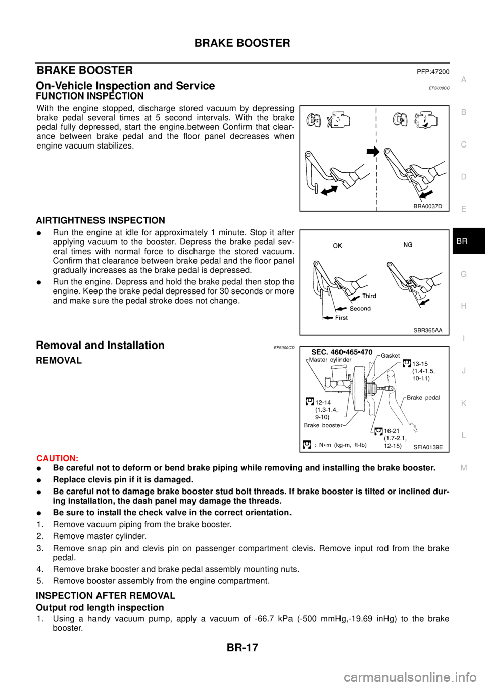
With the engine stopped, discharge stored vacuum by depressing
brake pedal several times at 5 second intervals. With the brake
pedal fully depressed, start the engine.between Confirm that clear-
ance between brake pedal and the floor panel decreases when
engine vacuum stabilizes.
AIRTIGHTNESS INSPECTION
lRun the engine at idle for approximately 1 minute. Stop it after
applying vacuum to the booster. Depress the brake pedal sev-
eral times with normal force to discharge the stored vacuum.
Confirm that clearance between brake pedal and the floor panel
gradually increases as the brake pedal is depressed.
lRun the engine. Depress and hold the brake pedal then stop the
engine. Keep the brake pedal depressed for 30 seconds or more
and make sure the pedal stroke does not change.
Removal and InstallationEFS000CD
REMOVAL
CAUTION:
lBe careful not to deform or bend brake piping while removing and installing the brake booster.
lReplace clevis pin if it is damaged.
lBe careful not to damage brake booster stud bolt threads. If brake booster is tilted or inclined dur-
ing installation, the dash panel may damage the threads.
lBe sure to install the check valve in the correct orientation.
1. Remove vacuum piping from the brake booster.
2. Remove master cylinder.
3. Remove snap pin and clevis pin on passenger compartment clevis. Remove input rod from the brake
pedal.
4. Remove brake booster and brake pedal assembly mounting nuts.
5. Remove booster assembly from the engine compartment.
INSPECTION AFTER REMOVAL
Output rod length inspection
1. Using a handy vacuum pump, apply a vacuum of -66.7 kPa (-500 mmHg,-19.69 inHg) to the brake
booster.
BRA0037D
SBR365AA
SFIA0139E
Page 852 of 3066
BR-18
BRAKE BOOSTER
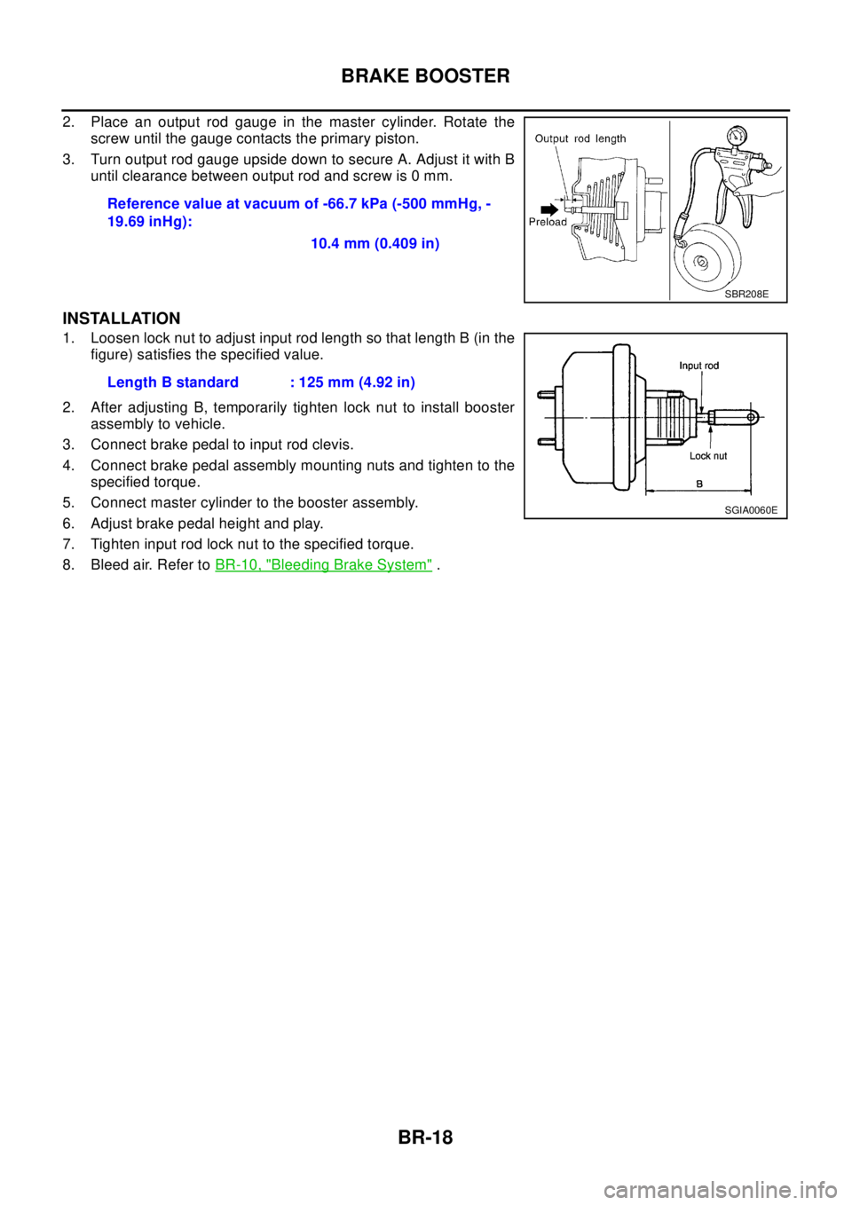
2. Place an output rod gauge in the master cylinder. Rotate the
screw until the gauge contacts the primary piston.
3. Turn output rod gauge upside down to secure A. Adjust it with B
until clearance between output rod and screw is 0 mm.
INSTALLATION
1. Loosen lock nut to adjust input rod length so that length B (in the
figure) satisfies the specified value.
2. After adjusting B, temporarily tighten lock nut to install booster
assembly to vehicle.
3. Connect brake pedal to input rod clevis.
4. Connect brake pedal assembly mounting nuts and tighten to the
specified torque.
5. Connect master cylinder to the booster assembly.
6. Adjust brake pedal height and play.
7. Tighten input rod lock nut to the specified torque.
8. Bleed air. Refer toBR-10, "
Bleeding Brake System". Reference value at vacuum of -66.7 kPa (-500 mmHg, -
19.69 inHg):
10.4 mm (0.409 in)
SBR208E
Length B standard : 125 mm (4.92 in)
SGIA0060E
Page 867 of 3066

SERVICE DATA AND SPECIFICATIONS (SDS)
BR-33
C
D
E
G
H
I
J
K
L
MA
B
BR
SERVICE DATA AND SPECIFICATIONS (SDS)PFP:00030
General SpecificationsEFS000CQ
Brake PedalEFS000CR
Check ValveEF S0 00 CS
Brake BoosterEFS000CT
Vacuum type
Front Disc BrakeEFS000CU
Front brakeBrake model AD31VD
Cylinder bore diameter 44.4´2(1.748´0.08)
Pad
Length x width x thickness132.0´52.5´11 . 0
(5.20´2.067´0.433)
Rotor outer diameter x thickness 280´28 (11.02´1.10)
Rear brakeBrake model ADV9VA
Cylinder bore diameter 34.9 (1.374)
Pad
Length x width x thickness83.0´33.0´8.5
(3.268´1.299´0.335)
Rotor outer diameter x thickness 292´16 (11.50´0.63)
Master cylinder Cylinder bore diameter 25.4 (1)
Control valve Valve model Electronic control type
Brake booster Booster model C215T
Diaphragm diameterPrimary 230 (9.06)
Secondary 205 (8.07)
Recommended brake fluid DOT 3 or DOT 4
Free play (at pedal top surface) 3 - 11 mm (0.12 - 0.43 in)
Looseness at clevis pin (at pedal top surface) 1 - 3 mm (0.04 - 0.12 in)
Brake pedal height (from dash panel top surface)M/T model 156 - 166 mm (6.14 - 6.54 in)
A/T model 164 - 174 mm (6.46 - 6.85 in)
Depressed pedal height under force of 490 N (50 kg,110.6 lb)
(from dash panel top surface)M/T model 80 mm (3.15 in) or more
A/T model 85 mm (3.35 in) or more
Clearance between threaded end of stop lamp switch and pedal stopper 0.74 - 1.96 mm (0.0291 - 0.0772 in)
Vacuum leakage [at vacuum of 66.7 kPa (-500 mmHg, -19.69
inHg)]Within 1.3 kPa (10 mmHg, 0.39 inHg) of vacuum for 15 sec-
onds
Vacuum leakage [at vacuum of -66.7 kPa (-500 mmHg, -19.69
inHg)]Within 3.3 kPa (25 mmHg, 0.98 inHg) of vacuum for 15 sec-
onds
Input rod installation standard dimension 125 mm (4.92 in)
Brake typeAD31VD
Brake padStandard thickness (new) 11 mm (0.43 in)
Repair limit thickness 2.0 mm (0.07 in)
Disc rotorStandard thickness (new) 28 mm (1.10 in)
Repair limit thickness 26 mm (1.02 in)
Runout limit 0.04 mm (0.0016 in)
Page 1139 of 3066
![NISSAN X-TRAIL 2003 Electronic User Guide ENGINE CONTROL SYSTEM
EC-25
[QR (WITH EURO-OBD)]
C
D
E
F
G
H
I
J
K
L
MA
EC
SYSTEM DESCRIPTION
The amount of fuel injected from the fuel injector is determined by the ECM. The ECM controls the length o](/img/5/57402/w960_57402-1138.png "NISSAN X-TRAIL 2003 Electronic User Guide ENGINE CONTROL SYSTEM
EC-25
[QR (WITH EURO-OBD)]
C
D
E
F
G
H
I
J
K
L
MA
EC
SYSTEM DESCRIPTION
The amount of fuel injected from the fuel injector is determined by the ECM. The ECM controls the length o")
ENGINE CONTROL SYSTEM
EC-25
[QR (WITH EURO-OBD)]
C
D
E
F
G
H
I
J
K
L
MA
EC
SYSTEM DESCRIPTION
The amount of fuel injected from the fuel injector is determined by the ECM. The ECM controls the length of
time the valve remains open (injection pulse duration). The amount of fuel injected is a program value in the
ECM memory. The program value is preset by engine operating conditions. These conditions are determined
by input signals (for engine speed and intake air) from both the crankshaft position sensor and the mass air
flow sensor.
VARIOUS FUEL INJECTION INCREASE/DECREASE COMPENSATION
In addition, the amount of fuel injected is compensated to improve engine performance under various operat-
ing conditions as listed below.
lDuring warm-up
lWhen starting the engine
lDuring acceleration
lHot-engine operation
lWhen selector lever is changed from “N” to “D”
lHigh-load, high-speed operation
lDuring deceleration
lDuring high engine speed operation
MIXTURE RATIO FEEDBACK CONTROL (CLOSED LOOP CONTROL)
The mixture ratio feedback system provides the best air-fuel mixture ratio for driveability and emission control.
The three way catalyst (manifold) can then better reduce CO, HC and NOx emissions. This system uses
heated oxygen sensor 1 in the exhaust manifold to monitor if the engine operation is rich or lean. The ECM
adjusts the injection pulse width according to the sensor voltage signal. For more information about heated
oxygen sensor 1, refer toEC-160
. This maintains the mixture ratio within the range of stoichiometric (ideal air-
fuel mixture).
This stage is referred to as the closed loop control condition.
Heated oxygen sensor 2 is located downstream of the three way catalyst (manifold). Even if the switching
characteristics of heated oxygen sensor 1 shift, the air-fuel ratio is controlled to stoichiometric by the signal
from heated oxygen sensor 2.
Open Loop Control
The open loop system condition refers to when the ECM detects any of the following conditions. Feedback
control stops in order to maintain stabilized fuel combustion.
lDeceleration and acceleration
lHigh-load, high-speed operation
lMalfunction of heated oxygen sensor 1 or its circuit
lInsufficient activation of heated oxygen sensor 1 at low engine coolant temperature
lHigh engine coolant temperature
lDuring warm-up
lAfter shifting from “N” to “D”
lWhen starting the engine
PBIB0121E
Page 1165 of 3066
![NISSAN X-TRAIL 2003 Electronic User Guide ON BOARD DIAGNOSTIC (OBD) SYSTEM
EC-51
[QR (WITH EURO-OBD)]
C
D
E
F
G
H
I
J
K
L
MA
EC
codes can be identified by using the CONSULT-II or GST. A DTC will be used as an example for how to read a
code.
A](/img/5/57402/w960_57402-1164.png "NISSAN X-TRAIL 2003 Electronic User Guide ON BOARD DIAGNOSTIC (OBD) SYSTEM
EC-51
[QR (WITH EURO-OBD)]
C
D
E
F
G
H
I
J
K
L
MA
EC
codes can be identified by using the CONSULT-II or GST. A DTC will be used as an example for how to read a
code.
A")
ON BOARD DIAGNOSTIC (OBD) SYSTEM
EC-51
[QR (WITH EURO-OBD)]
C
D
E
F
G
H
I
J
K
L
MA
EC
codes can be identified by using the CONSULT-II or GST. A DTC will be used as an example for how to read a
code.
A particular trouble code can be identified by the number of four-digit numeral flashes. The “zero” is indicated
by the number of ten flashes. The length of time the 1,000th-digit numeral flashes on and off is 1.2 seconds
consisting of an ON (0.6-second) - OFF (0.6-second) cycle.
The 100th-digit numeral and lower digit numerals consist of a 0.3-second ON and 0.3-second OFF cycle.
A change from one digit numeral to another occurs at an interval of 1.0-second OFF. In other words, the later
numeral appears on the display 1.3 seconds after the former numeral has disappeared.
A change from one trouble code to another occurs at an interval of 1.8-second OFF.
In this way, all the detected malfunctions are classified by their DTC numbers. The DTC “0000” refers to no
malfunction. (SeeEC-12, "
INDEX FOR DTC")
How to Erase Diagnostic Test Mode II (Self-diagnostic Results)
The DTC can be erased from the back up memory in the ECM by depressing accelerator pedal. Refer toEC-
49, "HOW TO SWITCH DIAGNOSTIC TEST MODE".
lIf the battery is disconnected, the DTC will be lost from the backup memory after approx 24 hours.
lBe careful not to erase the stored memory before starting trouble diagnoses.
DIAGNOSTIC TEST MODE II — HEATED OXYGEN SENSOR 1 MONITOR
In this mode, the MI displays the condition of the fuel mixture (lean or rich) which is monitored by the heated
oxygen sensor 1.
*: Maintains conditions just before switching to open loop.
To check the heated oxygen sensor 1 function, start engine in the Diagnostic Test Mode II and warm it up until
engine coolant temperature indicator points to the middle of the gauge.
Next run engine at about 2,000 rpm for about 2 minutes under no-load conditions. Then make sure that the MI
comes ON more than 5 times within 10 seconds with engine running at 2,000 rpm under no-load.
OBD System Operation ChartEBS00BMA
RELATIONSHIP BETWEEN MI, 1ST TRIP DTC, DTC, AND DETECTABLE ITEMS
lWhen a malfunction is detected for the first time, the 1st trip DTC and the 1st trip freeze frame data are
stored in the ECM memory.
SEF952W
MI Fuel mixture condition in the exhaust gas Air fuel ratio feedback control condition
ON Lean
Closed loop system
OFF Rich
*Remains ON or OFF Any condition Open loop system
Page 1457 of 3066
![NISSAN X-TRAIL 2003 Electronic User Guide INJECTOR CIRCUIT
EC-343
[QR (WITH EURO-OBD)]
C
D
E
F
G
H
I
J
K
L
MA
EC
INJECTOR CIRCUITPFP:16600
Component DescriptionEBS00BDE
The fuel injector is a small, precise solenoid valve. When the ECM
suppli](/img/5/57402/w960_57402-1456.png "NISSAN X-TRAIL 2003 Electronic User Guide INJECTOR CIRCUIT
EC-343
[QR (WITH EURO-OBD)]
C
D
E
F
G
H
I
J
K
L
MA
EC
INJECTOR CIRCUITPFP:16600
Component DescriptionEBS00BDE
The fuel injector is a small, precise solenoid valve. When the ECM
suppli")
INJECTOR CIRCUIT
EC-343
[QR (WITH EURO-OBD)]
C
D
E
F
G
H
I
J
K
L
MA
EC
INJECTOR CIRCUITPFP:16600
Component DescriptionEBS00BDE
The fuel injector is a small, precise solenoid valve. When the ECM
supplies a ground to the injector circuit, the coil in the injector is
energized. The energized coil pulls the needle valve back and allows
fuel to flow through the injector into the intake manifold. The amount
of fuel injected depends upon the injection pulse duration. Pulse
duration is the length of time the injector remains open. The ECM
controls the injection pulse duration based on engine fuel needs.
CONSULT-II Reference Value in Data Monitor ModeEBS00BDF
Specification data are reference values.
ECM Terminals and Reference ValueEBS00BDG
Specification data are reference values and are measured between each terminal and body ground.
CAUTION:
Do not use ECM ground terminals when measuring input/output voltage. Doing so may result in dam-
age to the ECM's transistor. Use a ground other than ECM terminals, such as the ground.
: Average voltage for pulse signal (Actual pulse signal can be confirmed by oscilloscope.)
SEF375Z
MONITOR ITEM CONDITION SPECIFICATION
B/FUEL SCHDL
lEngine: After warming up
lShiftlever:N
lAir conditioner switch: OFF
lNo-loadIdle 2.5-3.5msec
2,000 rpm 2.5 - 3.5 msec
INJ PULSE-B1
lEngine: After warming up
lShiftlever:N
lAir conditioner switch: OFF
lNo-loadIdle 2.0-3.0msec
2,000 rpm 1.9 - 2.9 msec
TER-
MINAL
NO.WIRE
COLORITEM CONDITION DATA (DC Voltage)
101
102
103
104R/B
Y/B
G/B
L/BInjector No. 1
Injector No. 2
Injector No. 3
Injector No. 4[Engineisrunning]
lWarm-up condition
lIdle speedBATTERY VOLTAGE
(11 - 14V)
[Engineisrunning]
lWarm-up condition
lEngine speed is 2,000 rpmBATTERY VOLTAGE
(11 - 14V)
PBIB0529E
PBIB0530E