roof NISSAN X-TRAIL 2003 Electronic Owner's Guide
[x] Cancel search | Manufacturer: NISSAN, Model Year: 2003, Model line: X-TRAIL, Model: NISSAN X-TRAIL 2003Pages: 3066, PDF Size: 51.47 MB
Page 2820 of 3066
RF-8
SUNROOF
SUNROOF UNIT
Removal
CAUTION:
lRemoval and installation of sunroof unit require 2 workers.
lWhen taking sunroof unit out, use shop cloths to protect seats and trim from damage.
lAfter installing sunroof unit and glass lid, be sure to carry out the leak test to confirm there is no
more leakage.
1. Remove headlining. Refer toEI-29, "
HEADLINING"
2. Disconnect drain hoses (4).
3. Disconnect interior lamp harness.
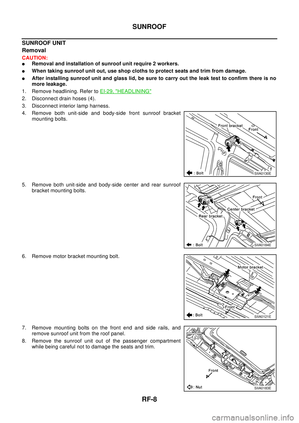
4. Remove both unit-side and body-side front sunroof bracket
mounting bolts.
5. Remove both unit-side and body-side center and rear sunroof
bracket mounting bolts.
6. Remove motor bracket mounting bolt.
7. Remove mounting bolts on the front end and side rails, and
remove sunroof unit from the roof panel.
8. Remove the sunroof unit out of the passenger compartment
while being careful not to damage the seats and trim.
SIIA0130E
SIIA0184E
SIIA0121E
SIIA0183E
Page 2821 of 3066
SUNROOF
RF-9
C
D
E
F
G
H
J
K
L
MA
B
RF
Installation
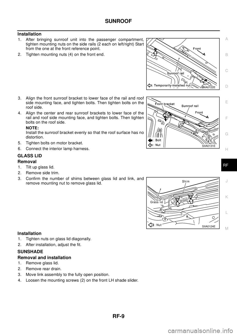
1. After bringing sunroof unit into the passenger compartment,
tighten mounting nuts on the side rails (2 each on left/right) Start
from the one at the front reference point.
2. Tighten mounting nuts (4) on the front end.
3. Align the front sunroof bracket to lower face of the rail and roof
side mounting face, and tighten bolts. Then tighten bolts on the
roof side.
4. Align the center and rear sunroof brackets to lower face of the
rail and roof side mounting face, and tighten bolts. Then tighten
bolts on the roof side.
NOTE:
Install the sunroof bracket evenly so that the roof surface has no
distortion.
5. Tighten bolts on motor bracket.
6. Connect the interior lamp harness.
GLASS LID
Removal
1. Tilt up glass lid.
2. Remove side trim.
3. Confirm the number of shims between glass lid and link, and
remove mounting nut to remove glass lid.
Installation
1. Tighten nuts on glass lid diagonally.
2. After installation, adjust the fit.
SUNSHADE
Removal and installation
1. Remove glass lid.
2. Remove rear drain.
3. Move link assembly to the fully open position.
4. Loosen the mounting screws (2) on the front LH shade slider.
SIIA0122E
SIIA0131E
SIIA0124E
Page 2822 of 3066
RF-10
SUNROOF
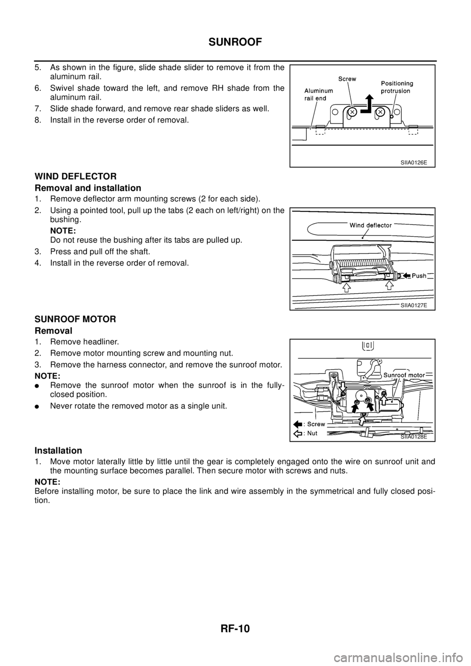
5. As shown in the figure, slide shade slider to remove it from the
aluminum rail.
6. Swivel shade toward the left, and remove RH shade from the
aluminum rail.
7. Slide shade forward, and remove rear shade sliders as well.
8. Install in the reverse order of removal.
WIND DEFLECTOR
Removal and installation
1. Remove deflector arm mounting screws (2 for each side).
2. Using a pointed tool, pull up the tabs (2 each on left/right) on the
bushing.
NOTE:
Do not reuse the bushing after its tabs are pulled up.
3. Press and pull off the shaft.
4. Install in the reverse order of removal.
SUNROOF MOTOR
Removal
1. Remove headliner.
2. Remove motor mounting screw and mounting nut.
3. Remove the harness connector, and remove the sunroof motor.
NOTE:
lRemove the sunroof motor when the sunroof is in the fully-
closed position.
lNever rotate the removed motor as a single unit.
Installation
1. Move motor laterally little by little until the gear is completely engaged onto the wire on sunroof unit and
the mounting surface becomes parallel. Then secure motor with screws and nuts.
NOTE:
Before installing motor, be sure to place the link and wire assembly in the symmetrical and fully closed posi-
tion.
SIIA0126E
SIIA0127E
SIIA0128E
Page 2824 of 3066
RFD-2
PRECAUTIONS
PRECAUTIONS
PFP:00001
CautionEDS00056
lBefore starting diagnosis of the vehicle, understand symptoms well. Perform correct and systematic oper-
ations.
lCheck for the correct installation status prior to removal or disassembly. When mating marks are required,
be sure they do not interfere with the function of the parts they are applied to.
lCarry out an overhaul in a clean work place. Using a dust proof room is recommended.
lBefore disassembly, using steam or white gasoline, completely remove sand and mud from the exterior of
the unit, preventing them from entering into the unit during disassembly or assembly.
lCheck appearance of the disassembled parts for damage, deformation, and abnormal wear. If a malfunc-
tion is detected, replace it with a new one.
lNormally replace lock pins, oil seals, and bearings with new ones every time they are removed.
lIn principle, tighten bolts or nuts gradually in several steps working diagonally from inside to outside. If
tightening sequence is specified, observe it.
lClean and flush the parts sufficiently and blow them dry.
lBe careful not to damage the sliding surfaces and mating surfaces.
lWhen applying sealant, remove the old sealant from the mounting surface; then remove any moisture, oil,
and foreign materials from the application and mounting surfaces.
lAlways use shop paper for cleaning the inside of components.
lAvoid using cotton gloves or a shop cloth to prevent entering of lint.
lDuring assembly, observe the specified tightening torque, and apply new differential oil, Vaseline, or Nis-
san MP Special Grease No. 2, as specified for each vehicle, when necessary.
lDo not reuse drained oil. Discard waste oil after oil changes or part treatment in accordance with local
laws and regulations.
Precautions for Brake SystemEDS000HX
lWhen installing rubber parts, final tightening must be carried out
under unladen condition* with tires on ground.
*: Fuel, radiator coolant and engine oil full. Spare tire, jack,
hand tools and mats in designated positions.
lAfter installing removed suspension parts, check wheel align-
ment and adjust if necessary.
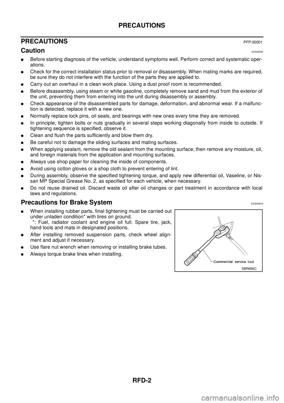
lUse flare nut wrench when removing or installing brake tubes.
lAlways torque brake lines when installing.
SBR686C
Page 2973 of 3066

PRECAUTIONS
TF-3
C
E
F
G
H
I
J
K
L
MA
B
TF
PRECAUTIONSPFP:00001
CautionEDS0004O
lDo not reuse the drained transfer oil.
lCheck the oil level with the vehicle on the level ground.
lDuring removal and installation, be careful not to allow foreign material such as dust or dirt to enter into
the transfer unit.
lBefore starting diagnosis of the vehicle, understand trouble symptoms well. Perform correct and system-
atic operations.
lCheck for the correct installation status prior to removal or disassembly. If mating marks are required, be
certain they do not interfere with the function of the parts they are applied to.
lCarry out the work in a clean work place. Using a dustproof room is recommended.
lBefore disassembly, using steam or white gasoline, completely remove sand and mud from the exterior of
the unit, preventing them from entering into the unit during disassembly or assembly.
lCheck appearance of the disassembled parts for damage, deformation, and abnormal wear. If a malfunc-
tion is detected, replace it with a new one.
lNormally replace O-rings, oil seals, bearings, and lock nuts with new ones every time they are removed.
lIn principle, tighten bolts or nuts gradually in several steps working diagonally from inside to outside. If
tightening sequence is specified, observe it.
lClean and flush the parts sufficiently and blow them dry.
lBe careful not to damage sliding surfaces and mating surfaces.
lAlways use shop paper for cleaning the inside of components.
lDo not use cotton gloves or a shop cloth. Using them may leave lint on the surface of the parts.
lDuring assembly always tighten bolts and screws to specified torque. new transfer oil a petroleum jelly
such as "Vaseline", or multi-purpose grease as appropriate.
lDiscard waste oil after oil changes or part treatment in accordance with local laws and regulations.