height adjustment NISSAN X-TRAIL 2003 Electronic Repair Manual
[x] Cancel search | Manufacturer: NISSAN, Model Year: 2003, Model line: X-TRAIL, Model: NISSAN X-TRAIL 2003Pages: 3066, PDF Size: 51.47 MB
Page 745 of 3066

BL-1
BODY, LOCK & SECURITY SYSTEM
IBODY
CONTENTS
C
D
E
F
G
H
J
K
L
M
SECTION
A
B
BL
BODY, LOCK & SECURITY SYSTEM
PRECAUTIONS .......................................................... 3
Precautions .............................................................. 3
HOOD ......................................................................... 4
Fitting Adjustment .................................................... 4
FRONT END HEIGHT ADJUSTMENT AND LAT-
ERAL/LONGITUDIAL CLEARANCE ADJUST-
MENT .................................................................... 4
SURFACE HEIGHT ADJUSTMENT ..................... 4
Removal and Installation of Hood Assembly ............ 5
Removal and Installation of Hood Lock Control ....... 6
REMOVAL ............................................................. 6
INSTALLATION ..................................................... 7
Hood Lock Control Inspection .................................. 7
DOOR ......................................................................... 8
Fitting Adjustment .................................................... 8
FRONT DOOR ...................................................... 8
REAR DOOR ........................................................ 8
STRIKER ADJUSTMENT ..................................... 9
Removal and Installation .......................................... 9
Door Weatherstrip .................................................. 10
POWER DOOR LOCK SYSTEM ...............................11
System Description .................................................11
OPERATION ........................................................11
Component Parts and Harness Connector Location....11
Schematic .............................................................. 12
Wiring Diagram — D/LOCK — ............................... 13
Terminal and Reference Value for Time Control Unit... 17
Symptom Chart ...................................................... 17
Power Supply and Ground Circuit Check ............... 18
Door Lock/Unlock Switch Check ............................ 18
Door Key Cylinder Switch Check ........................... 19
Door Lock Actuator Check ..................................... 20
Door Switch Check ................................................. 21
Door Unlock Sensor Check .................................... 22
Key Switch Check .................................................. 23
POWER DOOR LOCK — SUPER LOCK — ............ 24
System Description ................................................ 24
OUTLINE ............................................................. 24
OPERATION ....................................................... 24
Schematic .............................................................. 26Wiring Diagram — S/LOCK — ............................... 27
Terminal and Reference Value for Time Control Unit... 33
Trouble Diagnoses ................................................. 34
PRELIMINARY CHECK ....................................... 34
SYMPTOM CHART ............................................. 35
Power Supply and Ground Circuit Check ............... 36
Door Lock/Unlock Switch Check ............................ 36
Door Key Cylinder Switch Check ............................ 37
Door Lock Actuator Check ...................................... 38
Door Switch Check ................................................. 39
Door Unlock Sensor Check .................................... 40
Key Switch Check ................................................... 41
Super Lock Actuator Check .................................... 42
NATS Release Signal Check .................................. 43
Ignition Switch “ON” Circuit Check ......................... 44
Remote Controller Signal Check ............................ 44
MULTI-REMOTE CONTROL SYSTEM ..................... 45
Component Parts and Harness Connector Location... 45
System Description ................................................. 45
FUNCTION .......................................................... 45
LOCK OPERATION ............................................. 45
UNLOCK OPERATION ........................................ 46
HAZARD REMINDER ......................................... 46
MULTI-REMOTE CONTROLLER ID CODE
ENTRY ................................................................ 46
Wiring Diagram — MULTI — .................................. 47
Terminal and Reference Value for Multi-remote
Control Unit ............................................................. 49
Symptom Chart ....................................................... 49
Remote Controller Battery Check ........................... 49
Power Supply and Ground Circuit Check ............... 50
Hazard Reminder Check ........................................ 51
ID Code Entry Procedure ....................................... 52
Remote Controller Battery Replacement ................ 53
FRONT DOOR LOCK ............................................... 54
Component Parts Location ..................................... 54
Inspection and Adjustment ..................................... 54
OUT SIDE HANDLE ROD ADJUSTMENT .......... 54
Removal and Installation ........................................ 54
REMOVAL ........................................................... 54
Page 748 of 3066
BL-4
HOOD
HOOD
PFP:65100
Fitting AdjustmentEIS000KF
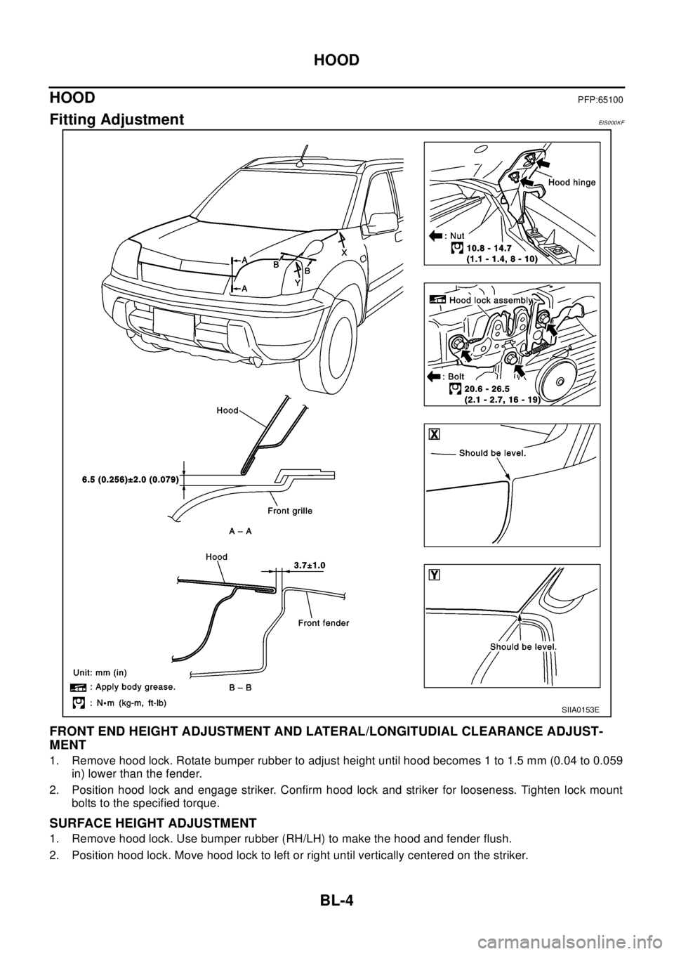
FRONT END HEIGHT ADJUSTMENT AND LATERAL/LONGITUDIAL CLEARANCE ADJUST-
MENT
1. Remove hood lock. Rotate bumper rubber to adjust height until hood becomes 1 to 1.5 mm (0.04 to 0.059
in) lower than the fender.
2. Position hood lock and engage striker. Confirm hood lock and striker for looseness. Tighten lock mount
bolts to the specified torque.
SURFACE HEIGHT ADJUSTMENT
1. Remove hood lock. Use bumper rubber (RH/LH) to make the hood and fender flush.
2. Position hood lock. Move hood lock to left or right until vertically centered on the striker.
SIIA0153E
Page 749 of 3066
HOOD
BL-5
C
D
E
F
G
H
J
K
L
MA
B
BL
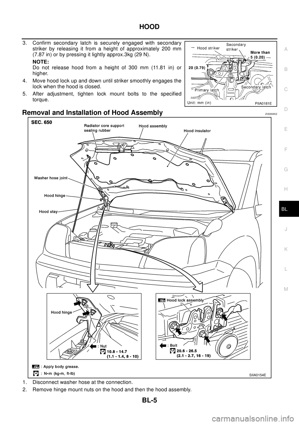
3. Confirm secondary latch is securely engaged with secondary
striker by releasing it from a height of approximately 200 mm
(7.87 in) or by pressing it lightly approx.3kg (29 N).
NOTE:
Do not release hood from a height of 300 mm (11.81 in) or
higher.
4. Move hood lock up and down until striker smoothly engages the
lock when the hood is closed.
5. After adjustment, tighten lock mount bolts to the specified
torque.
Removal and Installation of Hood AssemblyEIS000KG
1. Disconnect washer hose at the connection.
2. Remove hinge mount nuts on the hood and then the hood assembly.
PIIA0181E
SIIA0154E
Page 751 of 3066
HOOD
BL-7
C
D
E
F
G
H
J
K
L
MA
B
BL
INSTALLATION
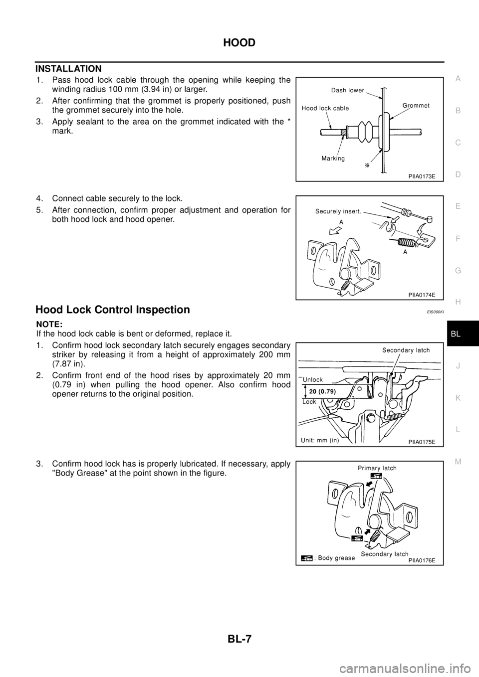
1. Pass hood lock cable through the opening while keeping the
winding radius 100 mm (3.94 in) or larger.
2. After confirming that the grommet is properly positioned, push
the grommet securely into the hole.
3. Apply sealant to the area on the grommet indicated with the *
mark.
4. Connect cable securely to the lock.
5. After connection, confirm proper adjustment and operation for
both hood lock and hood opener.
Hood Lock Control InspectionEIS000KI
NOTE:
If the hood lock cable is bent or deformed, replace it.
1. Confirm hood lock secondary latch securely engages secondary
striker by releasing it from a height of approximately 200 mm
(7.87 in).
2. Confirm front end of the hood rises by approximately 20 mm
(0.79 in) when pulling the hood opener. Also confirm hood
opener returns to the original position.
3. Confirm hood lock has is properly lubricated. If necessary, apply
"Body Grease" at the point shown in the figure.
PIIA0173E
PIIA0174E
PIIA0175E
PIIA0176E
Page 752 of 3066
BL-8
DOOR
DOOR
PFP:80100
Fitting AdjustmentEIS000KJ
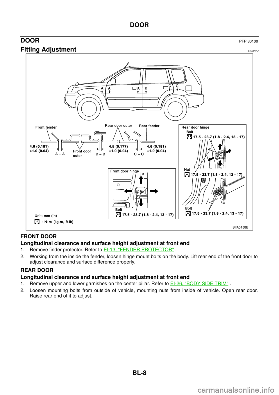
FRONT DOOR
Longitudinal clearance and surface height adjustment at front end
1. Remove finder protector. Refer toEI-13, "FENDER PROTECTOR".
2. Working from the inside the fender, loosen hinge mount bolts on the body. Lift rear end of the front door to
adjust clearance and surface difference properly.
REAR DOOR
Longitudinal clearance and surface height adjustment at front end
1. Remove upper and lower garnishes on the center pillar. Refer toEI-26, "BODY SIDE TRIM".
2. Loosen mounting bolts from outside of vehicle, mounting nuts from inside of vehicle. Open rear door.
Raise rear end of it to adjust.
SIIA0158E
Page 840 of 3066
BR-6
BRAKE PEDAL
BRAKE PEDAL
PFP:46501
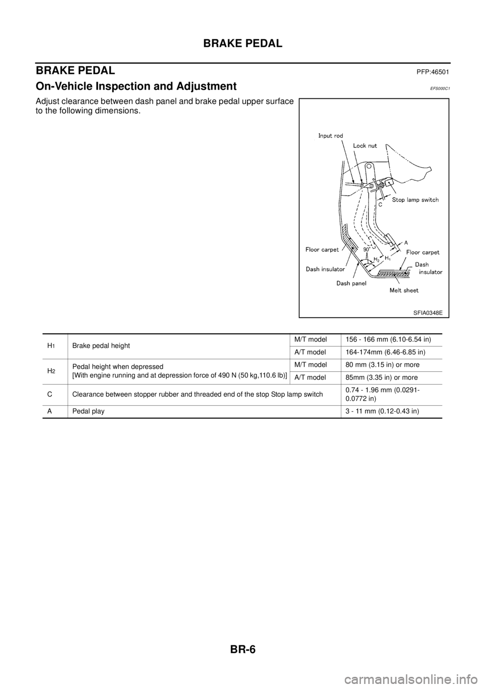
On-Vehicle Inspection and AdjustmentEFS000C1
Adjust clearance between dash panel and brake pedal upper surface
to the following dimensions.
SFIA0348E
H1Brake pedal heightM/T model 156 - 166 mm (6.10-6.54 in)
A/T model 164-174mm (6.46-6.85 in)
H
2Pedal height when depressed
[With engine running and at depression force of 490 N (50 kg,110.6 lb)]M/T model 80 mm (3.15 in) or more
A/T model 85mm (3.35 in) or more
C Clearance between stopper rubber and threaded end of the stop Stop lamp switch0.74 - 1.96 mm (0.0291-
0.0772 in)
A Pedal play3 - 11 mm (0.12-0.43 in)
Page 993 of 3066

CL-1
CLUTCH
C TRANSMISSION/TRANSAXLE
CONTENTS
D
E
F
G
H
I
J
K
L
M
SECTION
A
B
CL
CLUTCH
PRECAUTIONS .......................................................... 2
Caution ..................................................................... 2
PREPARATION ........................................................... 3
Special Service Tools ............................................... 3
Commercial Service Tool ......................................... 3
NOISE, VIBRATION, AND HARSHNESS (NVH)
TROUBLESHOOTING ................................................ 4
NVH Troubleshooting Chart ..................................... 4
CLUTCH PEDAL ........................................................ 5
On-vehicle Inspection and Adjustment ..................... 5
HEIGHT ADJUSTMENT ....................................... 5
CLUTCH SWITCH POSITION ADJUSTMENT ..... 5
FREE PLAY INSPECTION .................................... 6
CLEARANCE CHECK ........................................... 6
Removal and Installation .......................................... 6
INSPECTION AFTER REMOVAL ......................... 7
CLUTCH FLUID .......................................................... 8
Air Bleeding Procedure ............................................ 8
CLUTCH MASTER CYLINDER .................................. 9
Removal and Installation .......................................... 9
REMOVAL ............................................................. 9
INSTALLATION ..................................................... 9
Disassembly and Assembly ................................... 10
DISASSEMBLY ................................................... 10
INSPECTION AFTER DISASSEMBLY ............... 10
ASSEMBLY ......................................................... 10
OPERATING CYLINDER ...........................................11Removal and Installation ........................................ 11
REMOVAL ........................................................... 11
INSTALLATION ................................................... 11
Disassembly and Assembly .................................... 11
DISASSEMBLY ................................................... 11
INSPECTION AFTER DISASSEMBLY ................ 11
ASSEMBLY ......................................................... 11
CLUTCH PIPING ....................................................... 12
Removal and Installation ........................................ 12
CLUTCH RELEASE MECHANISM ........................... 13
Removal and Installation ........................................ 13
REMOVAL ........................................................... 13
INSPECTION AFTER REMOVEL ....................... 13
INSTALLATION ................................................... 13
CLUTCH DISC, CLUTCH COVER AND FLYWHEEL... 15
Removal and Installation ........................................ 15
REMOBAL ........................................................... 15
INSPECTION AND ADJUSTMENT AFTER
REMOVAL ........................................................... 15
INSTALLATION ................................................... 16
SERVICE DATA AND SPECIFICATIONS (SDS) ...... 17
Clutch Control System ............................................ 17
Clutch Master Cylinder ........................................... 17
Clutch Operating Cylinder ...................................... 17
Clutch Disk ............................................................. 17
Clutch Cover ........................................................... 17
Clutch Pedal ........................................................... 17
Page 997 of 3066
CLUTCH PEDAL
CL-5
D
E
F
G
H
I
J
K
L
MA
B
CL
CLUTCH PEDALPFP:46540
On-vehicle Inspection and AdjustmentECS0 01 W B
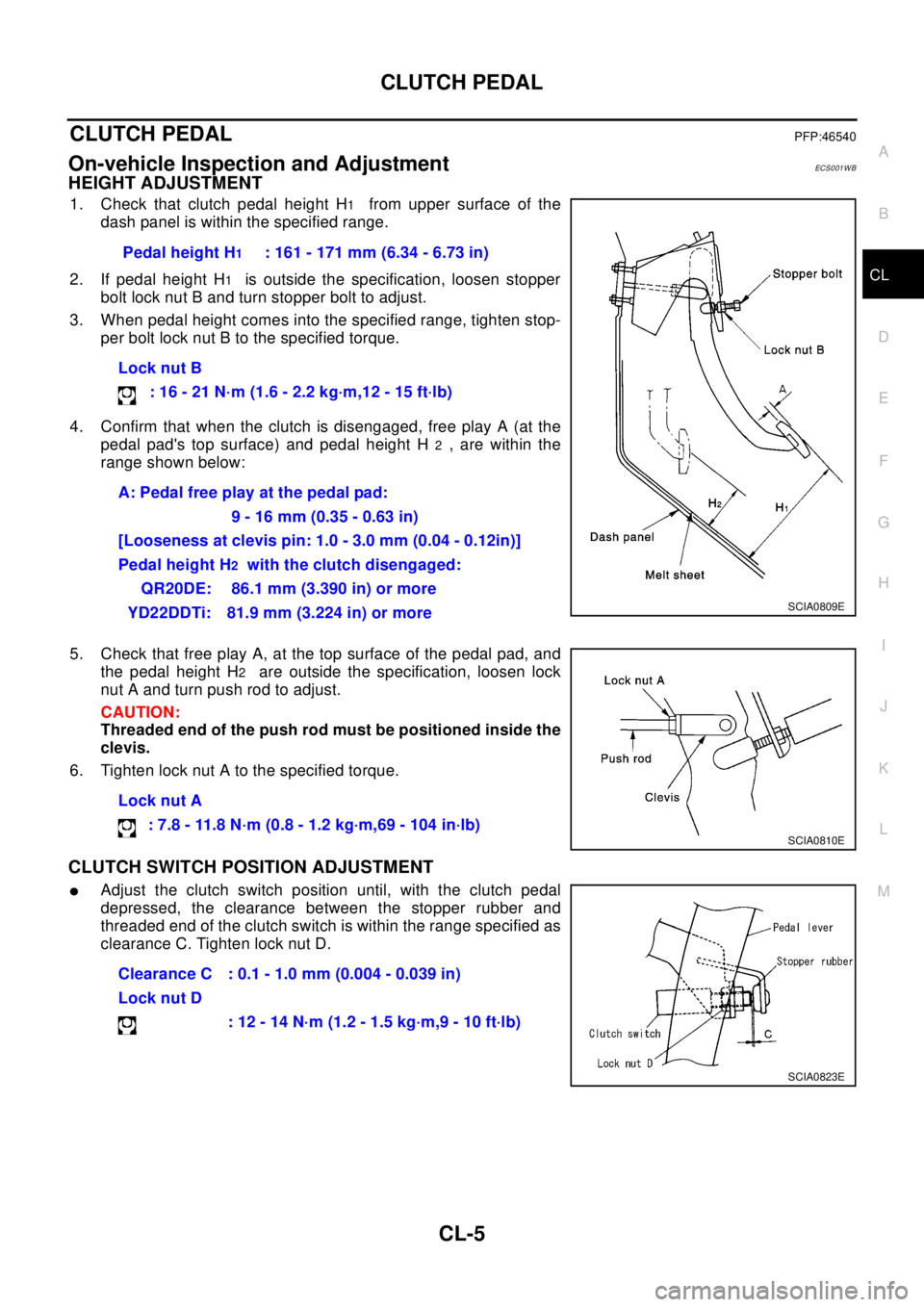
HEIGHT ADJUSTMENT
1. Check that clutch pedal height H1from upper surface of the
dash panel is within the specified range.
2. If pedal height H
1is outside the specification, loosen stopper
bolt lock nut B and turn stopper bolt to adjust.
3. When pedal height comes into the specified range, tighten stop-
per bolt lock nut B to the specified torque.
4. Confirm that when the clutch is disengaged, free play A (at the
pedal pad's top surface) and pedal height H
2, are within the
range shown below:
5. Check that free play A, at the top surface of the pedal pad, and
the pedal height H
2are outside the specification, loosen lock
nut A and turn push rod to adjust.
CAUTION:
Threaded end of the push rod must be positioned inside the
clevis.
6. Tighten lock nut A to the specified torque.
CLUTCH SWITCH POSITION ADJUSTMENT
lAdjust the clutch switch position until, with the clutch pedal
depressed, the clearance between the stopper rubber and
threaded end of the clutch switch is within the range specified as
clearance C. Tighten lock nut D.Pedal height H
1: 161 - 171 mm (6.34 - 6.73 in)
Lock nut B
:16-21N·m(1.6-2.2kg·m,12-15ft·lb)
A: Pedal free play at the pedal pad:
9 - 16 mm (0.35 - 0.63 in)
[Looseness at clevis pin: 1.0 - 3.0 mm (0.04 - 0.12in)]
Pedal height H
2with the clutch disengaged:
QR20DE: 86.1 mm (3.390 in) or more
YD22DDTi: 81.9 mm (3.224 in) or more
MAA0474DSCIA0809E
Lock nut A
: 7.8 - 11.8 N·m (0.8 - 1.2 kg·m,69 - 104 in·lb)
SCIA0810E
Clearance C : 0.1 - 1.0 mm (0.004 - 0.039 in)
Lock nut D
:12-14N·m(1.2-1.5kg·m,9-10ft·lb)
SCIA0823E
Page 1001 of 3066
CLUTCH MASTER CYLINDER
CL-9
D
E
F
G
H
I
J
K
L
MA
B
CL
CLUTCH MASTER CYLINDERPFP:30610
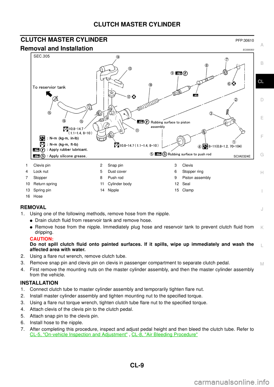
Removal and InstallationECS00353
REMOVAL
1. Using one of the following methods, remove hose from the nipple.
lDrain clutch fluid from reservoir tank and remove hose.
lRemove hose from the nipple. Immediately plug hose and reservoir tank to prevent clutch fluid from
dripping.
CAUTION:
Do not spill clutch fluid onto painted surfaces. If it spills, wipe up immediately and wash the
affected area with water.
2. Using a flare nut wrench, remove clutch tube.
3. Remove snap pin and clevis pin on clevis in passenger compartment to separate clutch pedal.
4. First remove the mounting nuts on the master cylinder assembly, and then the master cylinder assembly
from the vehicle.
INSTALLATION
1. Connect clutch tube to master cylinder assembly and temporarily tighten flare nut.
2. Install master cylinder assembly and tighten mounting nut to the specified torque.
3. Using a flare nut torque wrench, tighten clutch tube flare nut to the specified torque.
4. Attach clevis of the clevis pin to the clutch pedal.
5. Attach snap pin to the clevis pin.
6. Install hose to the nipple.
7. After completing this procedure, inspect and adjust pedal height and then bleed the clutch tube. Refer to
CL-5, "
On-vehicle Inspection and Adjustment",CL-8, "Air Bleeding Procedure"
SCIA0324E
1 Clevis pin 2 Snap pin 3 Clevis
4 Lock nut 5 Dust cover 6 Stopper ring
7 Stopper 8 Push rod 9 Piston assembly
10 Return spring 11 Cylinder body 12 Seal
13 Spring pin 14 Nipple 15 Clamp
16 Hose
Page 2433 of 3066
FRONT FOG LAMP
LT-35
C
D
E
F
G
H
I
J
L
MA
B
LT
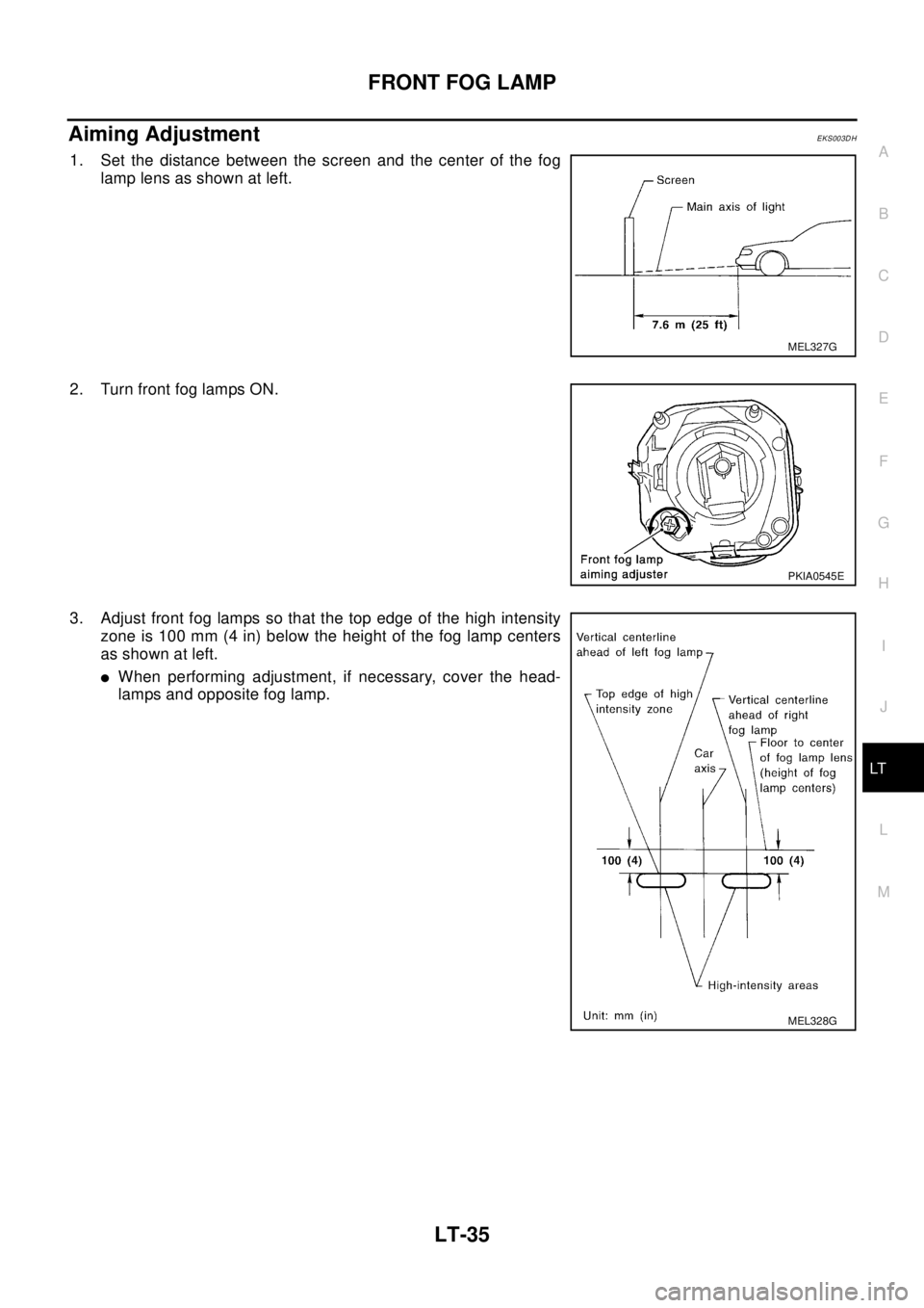
Aiming AdjustmentEKS003DH
1. Set the distance between the screen and the center of the fog
lamp lens as shown at left.
2. Turn front fog lamps ON.
3. Adjust front fog lamps so that the top edge of the high intensity
zone is 100 mm (4 in) below the height of the fog lamp centers
as shown at left.
lWhen performing adjustment, if necessary, cover the head-
lamps and opposite fog lamp.
MEL327G
PKIA0545E
MEL328G