door lock NISSAN X-TRAIL 2003 Electronic Repair Manual
[x] Cancel search | Manufacturer: NISSAN, Model Year: 2003, Model line: X-TRAIL, Model: NISSAN X-TRAIL 2003Pages: 3066, PDF Size: 51.47 MB
Page 623 of 3066
TROUBLE DIAGNOSIS
ATC-45
C
D
E
F
G
H
I
K
L
MA
B
AT C
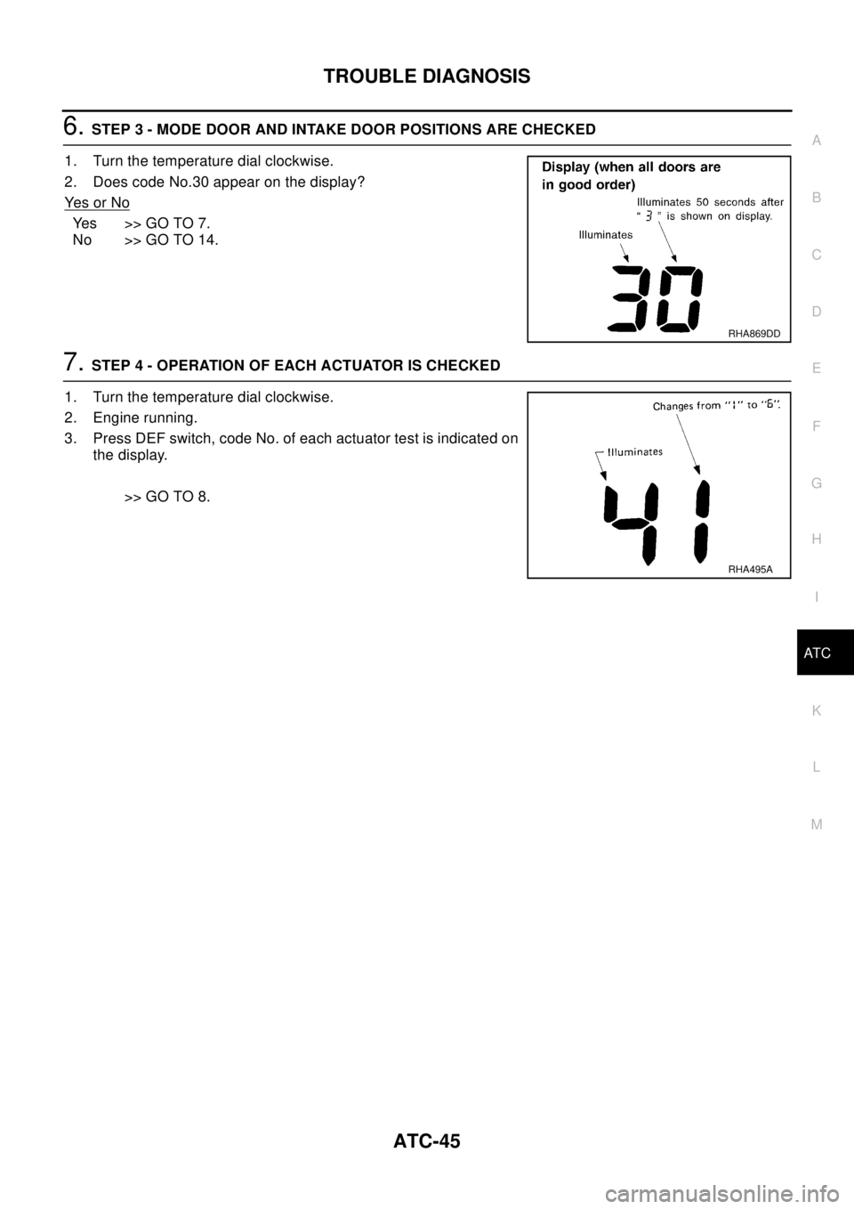
6.STEP 3 - MODE DOOR AND INTAKE DOOR POSITIONS ARE CHECKED
1. Turn the temperature dial clockwise.
2. Does code No.30 appear on the display?
Ye s o r N o
Yes >>GOTO7.
No >> GO TO 14.
7.STEP 4 - OPERATION OF EACH ACTUATOR IS CHECKED
1. Turn the temperature dial clockwise.
2. Engine running.
3. Press DEF switch, code No. of each actuator test is indicated on
the display.
>> GO TO 8.
RHA869DD
RHA495A
Page 624 of 3066
ATC-46
TROUBLE DIAGNOSIS
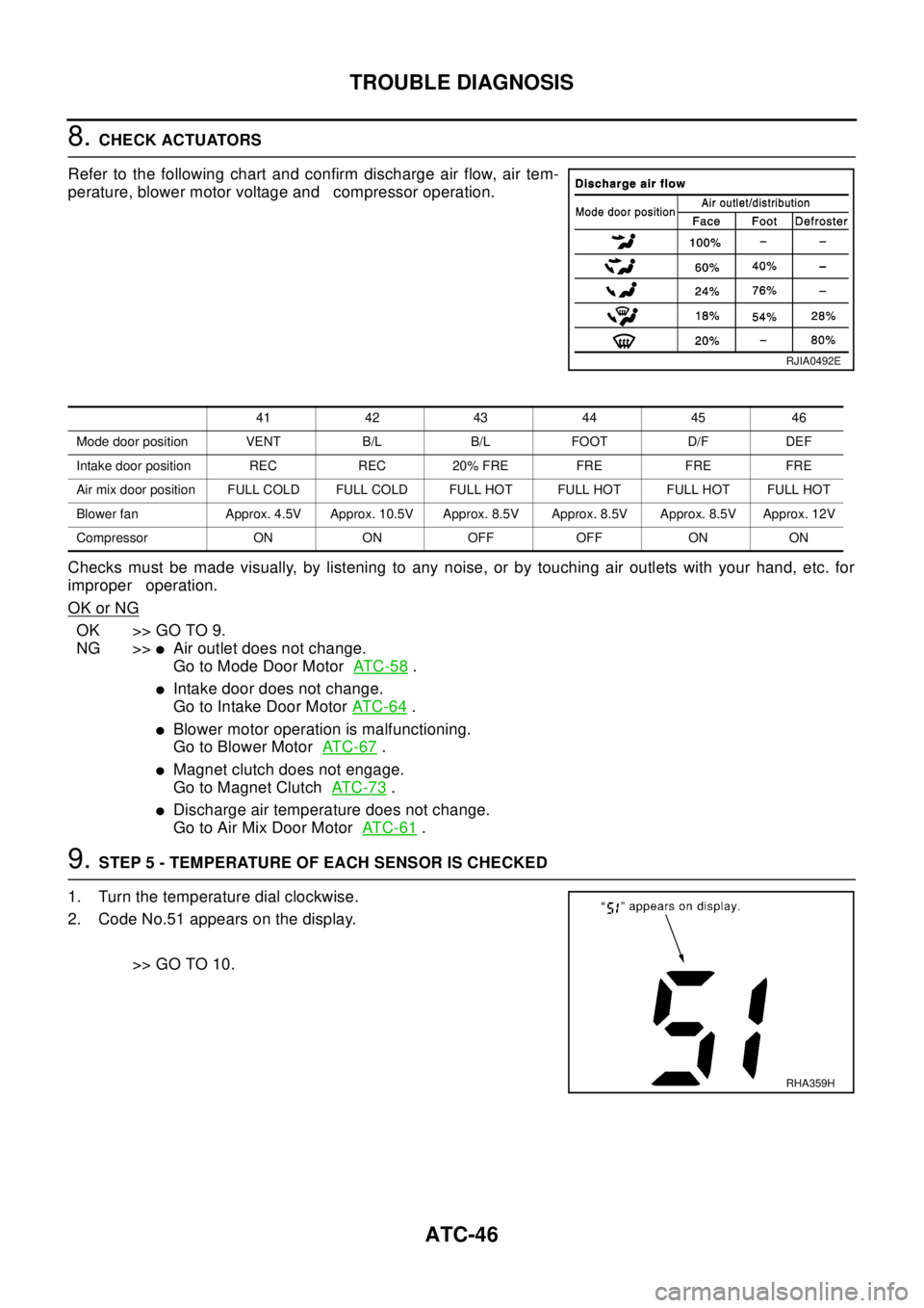
8.CHECK ACTUATORS
Refer to the following chart and confirm discharge air flow, air tem-
perature, blower motor voltage and compressor operation.
Checks must be made visually, by listening to any noise, or by touching air outlets with your hand, etc. for
improper operation.
OK or NG
OK >> GO TO 9.
NG >>
lAir outlet does not change.
Go to Mode Door MotorAT C - 5 8
.
lIntake door does not change.
Go to Intake Door MotorAT C - 6 4
.
lBlower motor operation is malfunctioning.
Go to Blower MotorAT C - 6 7
.
lMagnet clutch does not engage.
Go to Magnet ClutchAT C - 7 3
.
lDischarge air temperature does not change.
Go to Air Mix Door MotorAT C - 6 1
.
9.STEP 5 - TEMPERATURE OF EACH SENSOR IS CHECKED
1. Turn the temperature dial clockwise.
2. Code No.51 appears on the display.
>> GO TO 10.
RJIA0492E
41 42 43 44 45 46
Mode door position VENT B/L B/L FOOT D/F DEF
Intake door position REC REC 20% FRE FRE FRE FRE
Air mix door position FULL COLD FULL COLD FULL HOT FULL HOT FULL HOT FULL HOT
Blower fan Approx. 4.5V Approx. 10.5V Approx. 8.5V Approx. 8.5V Approx. 8.5V Approx. 12V
Compressor ON ON OFF OFF ON ON
RHA359H
Page 725 of 3066

AUDIO
AV-3
C
D
E
F
G
H
I
J
L
MA
B
AV
AUDIOP F P : 2 8 111
System DescriptionEKS002F2
Refer to Owner's Manual for audio system operating instructions.
Power is supplied at all times
lthrough 15A fuse (No. 32, located in the fusible link and fuse block)
lto audio unit terminal 3
lto CD auto changer terminal 32.
With the ignition switch in the ACC or ON position, power is supplied
lthrough 10A fuse [No. 4, located in the fuse block (J/B)]
lto audio unit terminal 6,
lto CD auto changer terminal 36
Ground is supplied through the case of the audio unit.
Audio signals are supplied
lthrough audio unit terminals 5, 7, 9, 10, 11, 13, 15, 16
lto terminals 1 and 2 of front door speaker LH and RH,
lto terminals 1 and 2 of rear door speaker LH and RH and
lto terminals 1 and 2 of tweeter LH and RH (with 6 speakers)
NATS AUDIO LINK
Description
The link with the NATS IMMU implies that the audio unit can basically only be operated if connected to the
matching NATS IMMU to which the audio unit was initially fitted on the production line.
Since radio operation is impossible after the link with the NATS is disrupted theft of the audio unit is basically
useless since special equipment is required to reset the audio unit.
Initialization process for audio units that are linked to the NATS IMMU
New audio units will be delivered to the factories in the “NEW” state, i.e. ready to be linked with the vehicle's
NATS. When the audio unit in “NEW” state is first switched on at the factory, it will start up communication with
the vehicle's immobilizer control unit (IMMU) and send a code (the “audio unit Code”) to the IMMU. The IMMU
will then store this code, which is unique to each audio unit, in its (permanent) memory.
Upon receipt of the code by the IMMU, the NATS will confirm correct receipt of the audio unit code to the audio
unit. Hereafter, the audio unit will operate as normal.
During the initialization process, “NEW” is displayed on the audio unit display. Normally though, communica-
tion between audio unit and IMMU takes such a short time (300 ms) that the audio unit seems to switch on
directly without showing “NEW” on its display.
Normal operation
Each time the audio unit is switched on afterwards, the audio unit code will be verified between the audio unit
and the NATS before the audio unit becomes operational. During the code verification process, “WAIT” is
shown on the audio unit display. Again, the communication takes such a short time (300 ms) that the audio
unit seems to switch on directly without showing “WAIT” on its display.
When the radio is locked
In case of a audio unit being linked with the vehicle's NATS (immobilizer system), disconnection of the link
between the audio unit and the IMMU will cause the audio unit to switch into the lock (“SECURE”) mode in
which the audio unit is fully inoperative. Hence, repair of the audio unit is basically impossible, unless the
audio unit is reset to the “NEW” state for which special decoding equipment is required.
Clarion has provided their authorized service representatives with so called “decoder boxes” which can bring
the audio unit back to the “NEW” state, enabling the audio unit to be switched on after which repair can be car-
ried out. Subsequently, when the repaired audio unit is delivered to the final user again, it will be in the “NEW”
state to enable re-linking the audio unit to the vehicle's immobilizer system. As a result of the above, repair of
the audio unit can only be done by an authorized Clarion representative (when the owner of the vehicle
requests repair and can show personal identification).
Page 741 of 3066

TIME CONTROL UNIT
BCS-3
C
D
E
F
G
H
I
J
L
MA
B
BCS
TIME CONTROL UNITPFP:28491
DescriptionEKS002ZU
OUTLINE
The time control unit totally controls the following body electrical system operations.
lWarning chime
lRear defogger
lPower door lock
lInterior lamp
INPUT/OUTPUT
System Input Output
PowerdoorlockDoor lock and unlock switch
Door switches
Door unlock sensor
Door key cylinder switch (driver side)Door lock actuators
Warning chimeKey switch (Insert)
Ignition switch (ON)
Lighting switch (1st)
Front door switch (driver side)
Door unlock sensorWarning chime (located in time control unit)
Rear window defoggerIgnition switch (ON)
Rear window defogger switchRear window defogger relay
Interior lampDoor switches
Front door unlock sensor
Ignition switch (ON)
Key switch (Insert)Interior lamp
Page 743 of 3066

TIME CONTROL UNIT
BCS-5
C
D
E
F
G
H
I
J
L
MA
B
BCS
Time Control Unit Inspection TableEKS002ZW
Te r m i n a l
No.Wire
colorConnections Operation conditionVo l ta g e
(Approxi-
mate values)
1 L/B Power source (Fuse) — 12V
3 L/Y Super lock actuator Door key cylinder switchFree 0V
Unlocked 12V
4G/RPassenger and rear doors lock
actuatorDoor lock/unlock switchFree 0V
Unlocked 12V
6 Y/R Super lock actuator Door key cylinder switchFree 0V
Locked 12V
10 W Power source (C/B) — 12V
11 L Driver's door lock actuator Door lock/unlock switchFree 0V
Unlocked 12V
14 R/B Door lock actuator Door lock/unlock switchFree 0V
Locked 12V
16 B Ground — 0V
17 G Ignition switch (ON) — 12V
18 W/L Ignition key switch (Insert) Key inserted®key removed from IGN key cylinder 12V®0V
19 R/L Lighting switch 1ST, 2ND position: ON®OFF 12V®0V
20 GY Door lock/Unlock switch Neutral®Locks 5V®0V
23 PU Door lock/Unlock switch Neutral®Unlocks 5V®0V
24 OR/L Door key cylinder switch OFF (Neutral)®ON (Locked) 5V®0V
25 W/L Door key cylinder switch OFF (Neutral)®ON (Unlocked) 5V®0V
26 R/Y Interior room lampWhen interior room lamp is operated using remote control-
ler (Lamp switch is “DOOR” position)12V®0V
27 G/W Rear window defogger relay OFF®ON (Ignition key is in “ON” position) 12V®0V
28 Y/G Driver door unlock sensor Driver door: Locked®Unlocked 5V®0V
29 Y/L Passenger door unlock sensor Passenger door: Locked®Unlocked 5V®0V
30 R Doorswitchdriverside OFF(closed)®ON (open) 5V®0V
31 R/W Passenger and rear doors switch OFF (closed)®ON (open) 5V®0V
32 OR Multi-remote control unitRemote controller lock button is pushed.
(Ignition switch is not at “ON” position)0V®5V
33 P/L Multi-remote control unitRemote controller unlock button is pushed.
(Ignition switch is not at “ON” position)0V®5V
35 LG/B Rear window defogger switch OFF®ON 5V®0V
Page 745 of 3066

BL-1
BODY, LOCK & SECURITY SYSTEM
IBODY
CONTENTS
C
D
E
F
G
H
J
K
L
M
SECTION
A
B
BL
BODY, LOCK & SECURITY SYSTEM
PRECAUTIONS .......................................................... 3
Precautions .............................................................. 3
HOOD ......................................................................... 4
Fitting Adjustment .................................................... 4
FRONT END HEIGHT ADJUSTMENT AND LAT-
ERAL/LONGITUDIAL CLEARANCE ADJUST-
MENT .................................................................... 4
SURFACE HEIGHT ADJUSTMENT ..................... 4
Removal and Installation of Hood Assembly ............ 5
Removal and Installation of Hood Lock Control ....... 6
REMOVAL ............................................................. 6
INSTALLATION ..................................................... 7
Hood Lock Control Inspection .................................. 7
DOOR ......................................................................... 8
Fitting Adjustment .................................................... 8
FRONT DOOR ...................................................... 8
REAR DOOR ........................................................ 8
STRIKER ADJUSTMENT ..................................... 9
Removal and Installation .......................................... 9
Door Weatherstrip .................................................. 10
POWER DOOR LOCK SYSTEM ...............................11
System Description .................................................11
OPERATION ........................................................11
Component Parts and Harness Connector Location....11
Schematic .............................................................. 12
Wiring Diagram — D/LOCK — ............................... 13
Terminal and Reference Value for Time Control Unit... 17
Symptom Chart ...................................................... 17
Power Supply and Ground Circuit Check ............... 18
Door Lock/Unlock Switch Check ............................ 18
Door Key Cylinder Switch Check ........................... 19
Door Lock Actuator Check ..................................... 20
Door Switch Check ................................................. 21
Door Unlock Sensor Check .................................... 22
Key Switch Check .................................................. 23
POWER DOOR LOCK — SUPER LOCK — ............ 24
System Description ................................................ 24
OUTLINE ............................................................. 24
OPERATION ....................................................... 24
Schematic .............................................................. 26Wiring Diagram — S/LOCK — ............................... 27
Terminal and Reference Value for Time Control Unit... 33
Trouble Diagnoses ................................................. 34
PRELIMINARY CHECK ....................................... 34
SYMPTOM CHART ............................................. 35
Power Supply and Ground Circuit Check ............... 36
Door Lock/Unlock Switch Check ............................ 36
Door Key Cylinder Switch Check ............................ 37
Door Lock Actuator Check ...................................... 38
Door Switch Check ................................................. 39
Door Unlock Sensor Check .................................... 40
Key Switch Check ................................................... 41
Super Lock Actuator Check .................................... 42
NATS Release Signal Check .................................. 43
Ignition Switch “ON” Circuit Check ......................... 44
Remote Controller Signal Check ............................ 44
MULTI-REMOTE CONTROL SYSTEM ..................... 45
Component Parts and Harness Connector Location... 45
System Description ................................................. 45
FUNCTION .......................................................... 45
LOCK OPERATION ............................................. 45
UNLOCK OPERATION ........................................ 46
HAZARD REMINDER ......................................... 46
MULTI-REMOTE CONTROLLER ID CODE
ENTRY ................................................................ 46
Wiring Diagram — MULTI — .................................. 47
Terminal and Reference Value for Multi-remote
Control Unit ............................................................. 49
Symptom Chart ....................................................... 49
Remote Controller Battery Check ........................... 49
Power Supply and Ground Circuit Check ............... 50
Hazard Reminder Check ........................................ 51
ID Code Entry Procedure ....................................... 52
Remote Controller Battery Replacement ................ 53
FRONT DOOR LOCK ............................................... 54
Component Parts Location ..................................... 54
Inspection and Adjustment ..................................... 54
OUT SIDE HANDLE ROD ADJUSTMENT .......... 54
Removal and Installation ........................................ 54
REMOVAL ........................................................... 54
Page 746 of 3066

BL-2
INSTALLATION .................................................... 55
Disassembly and Assembly .................................... 55
DISASSEMBLY ................................................... 55
ASSEMBLY ......................................................... 56
REAR DOOR LOCK .................................................. 57
Component Parts Location ..................................... 57
Inspection and Adjustment ..................................... 57
OUT SIDE HANDLE ROD ADJUSTMENT .......... 57
Removal and Installation ........................................ 57
REMOVAL ........................................................... 57
INSTALLATION .................................................... 58
Disassembly and Assembly .................................... 58
DISASSEMBLY ................................................... 58
ASSEMBLY ......................................................... 59
BACK DOOR ............................................................. 60
Fitting Adjustment ................................................... 60
VERTICAL/LATERAL CLEARANCE ADJUST-
MENT .................................................................. 60
Back Door Assembly .............................................. 61
REMOVAL AND INSTALLATION ......................... 61
INSPECTION ....................................................... 61
Removal and Installation of Back Door Handle ...... 61
Removal and Installation of Back Door Lock and
Actuator .................................................................. 62
Removal and Installation of Back Door Weatherstrip... 62
FUEL FILLER LID OPENER ..................................... 64
Component Parts Location ..................................... 64
THEFT WARNING SYSTEM ..................................... 65
Wiring Diagram — THEFT —/PRI-WIRE ................ 65
LHD MODELS ..................................................... 66
RHD MODELS ..................................................... 68NATS (NISSAN ANTI-THEFT SYSTEM) ...................70
Component Parts and Harness Connector Location... 70
System Description .................................................70
System Composition ...............................................71
Wiring Diagram — NATS — ....................................72
GASOLINE ENGINE MODELS ............................72
DIESEL ENGINE MODELS .................................73
CONSULT-II ............................................................74
CONSULT-II INSPECTION PROCEDURE ..........74
CONSULT-II DIAGNOSTIC TEST MODE FUNC-
TION ....................................................................74
HOW TO READ SELF-DIAGNOSTIC RESULTS...75
NATS SELF-DIAGNOSTIC RESULTS ITEM
CHART .................................................................75
Work Flow ...............................................................77
Trouble Diagnoses ..................................................78
SYMPTOM MATRIX CHART 1 ............................78
SYMPTOM MATRIX CHART 2 ............................79
DIAGNOSTIC SYSTEM DIAGRAM .....................79
Diagnostic Procedure 1 ...........................................80
Diagnostic Procedure 2 ...........................................80
Diagnostic Procedure 3 ...........................................82
Diagnostic Procedure 4 ...........................................83
Diagnostic Procedure 5 ...........................................85
Diagnostic Procedure 6 ...........................................85
Diagnostic Procedure 7 ...........................................86
Diagnostic Procedure 8 ...........................................88
How to Replace NATS IMMU ..................................89
Page 753 of 3066
DOOR
BL-9
C
D
E
F
G
H
J
K
L
MA
B
BL
STRIKER ADJUSTMENT
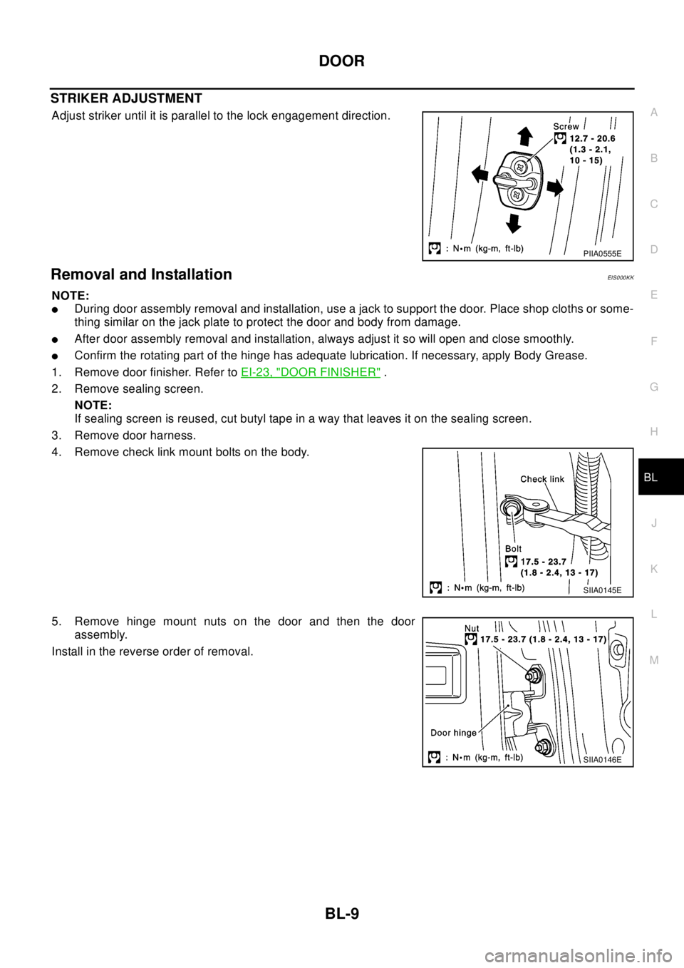
Adjust striker until it is parallel to the lock engagement direction.
Removal and InstallationEIS000KK
NOTE:
lDuring door assembly removal and installation, use a jack to support the door. Place shop cloths or some-
thing similar on the jack plate to protect the door and body from damage.
lAfter door assembly removal and installation, always adjust it so will open and close smoothly.
lConfirm the rotating part of the hinge has adequate lubrication. If necessary, apply Body Grease.
1. Remove door finisher. Refer toEI-23, "
DOOR FINISHER".
2. Remove sealing screen.
NOTE:
If sealing screen is reused, cut butyl tape in a way that leaves it on the sealing screen.
3. Remove door harness.
4. Remove check link mount bolts on the body.
5. Remove hinge mount nuts on the door and then the door
assembly.
Install in the reverse order of removal.
PIIA0555E
SIIA0145E
SIIA0146E
Page 755 of 3066
POWERDOORLOCKSYSTEM
BL-11
C
D
E
F
G
H
J
K
L
MA
B
BL
POWER DOOR LOCK SYSTEMPFP:24814
System DescriptionEIS001SE
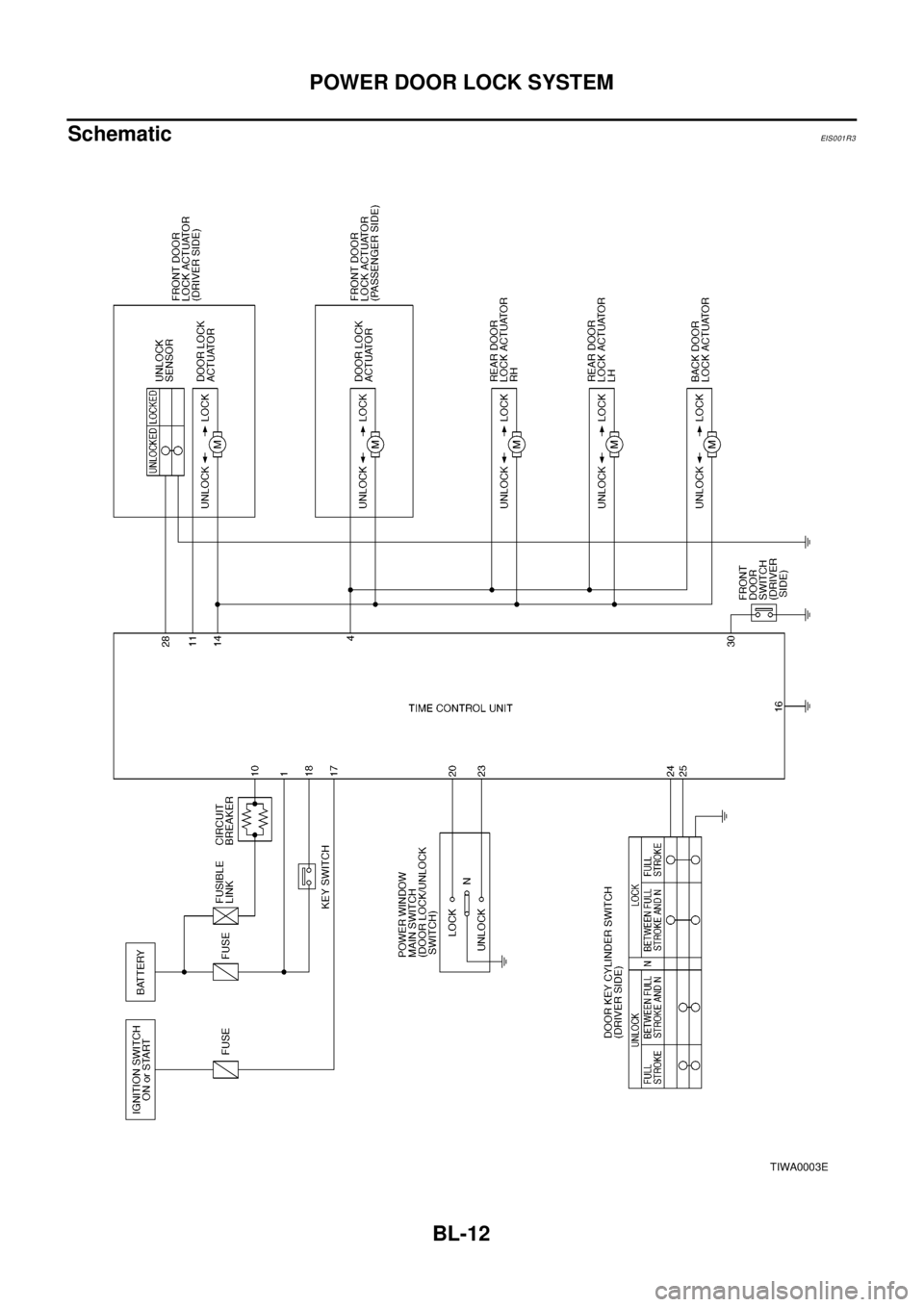
OPERATION
Power door lock/unlock operation by door key cylinder
lWith the key inserted into driver's door key cylinder, turning it to LOCK will lock all doors.
lWith the key inserted into driver's door key cylinder, turning it to UNLOCK will unlock all doors.
Power door lock/unlock operation by lock/unlock switch
lWith lock/unlock switch setting to LOCK will lock all doors.
lWith lock/unlock switch setting to UNLOCK will unlock all doors.
Key reminder system
lIf the ignition key is in the ignition key cylinder and driver door is open, setting lock/unlock switch, lock
knob, key or multi-remote controller to “LOCK” locks the door once but then immediately unlocks all doors.
(signal from door unlock sensor driver side)
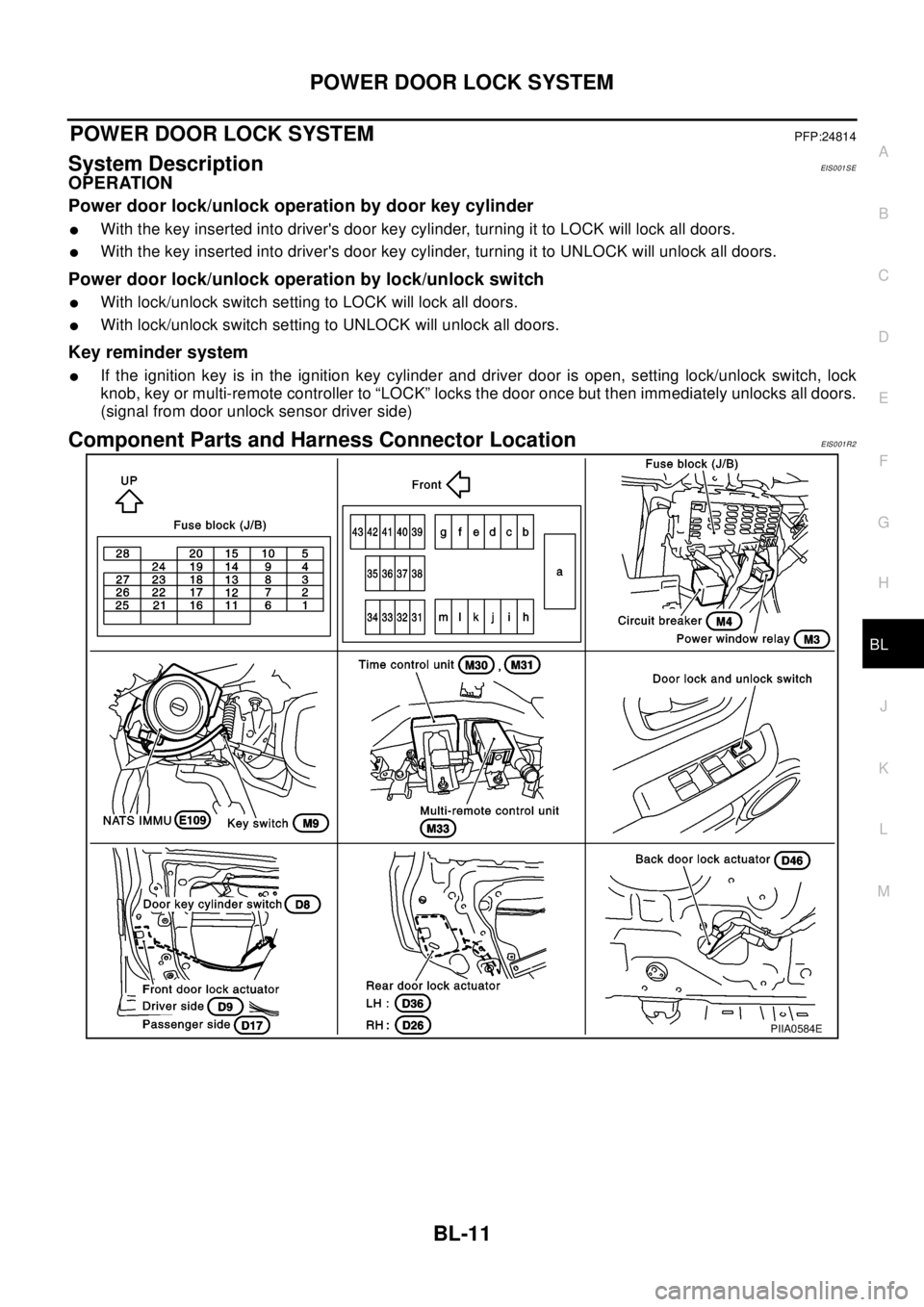
Component Parts and Harness Connector LocationEIS001R2
PIIA0584E
Page 756 of 3066
BL-12
POWER DOOR LOCK SYSTEM
Schematic
EIS0 01 R3
TIWA0003E