heating NISSAN X-TRAIL 2003 Electronic Service Manual
[x] Cancel search | Manufacturer: NISSAN, Model Year: 2003, Model line: X-TRAIL, Model: NISSAN X-TRAIL 2003Pages: 3066, PDF Size: 51.47 MB
Page 2481 of 3066
![NISSAN X-TRAIL 2003 Electronic Service Manual PRECAUTIONS
LU-15
[YD22DDTi]
C
D
E
F
G
H
I
J
K
L
MA
LU
[YD22DDTi]PRECAUTIONSPFP:00001
Precautions For Liquid GasketEBS00B00
REMOVAL OF LIQUID GASKET SEALING
lAfter removing the mounting bolts and nuts NISSAN X-TRAIL 2003 Electronic Service Manual PRECAUTIONS
LU-15
[YD22DDTi]
C
D
E
F
G
H
I
J
K
L
MA
LU
[YD22DDTi]PRECAUTIONSPFP:00001
Precautions For Liquid GasketEBS00B00
REMOVAL OF LIQUID GASKET SEALING
lAfter removing the mounting bolts and nuts](/img/5/57402/w960_57402-2480.png)
PRECAUTIONS
LU-15
[YD22DDTi]
C
D
E
F
G
H
I
J
K
L
MA
LU
[YD22DDTi]PRECAUTIONSPFP:00001
Precautions For Liquid GasketEBS00B00
REMOVAL OF LIQUID GASKET SEALING
lAfter removing the mounting bolts and nuts, disconnect and
remove the liquid gasket sealing using a seal cutter.
CAUTION:
Be careful not to damage the mating surfaces.
lIn areas where the cutter is difficult to use, use a plastic hammer
to lightly tap the areas where the liquid gasket is applied.
CAUTION:
If for some unavoidable reason a tool such as a flat-bladed
screwdriver is used, be careful not to damage the mating sur-
faces.
LIQUID GASKET APPLICATION PROCEDURE
1. Using a scraper, remove the old liquid gasket adhering to the
gasket application surface and the mating surface.
lRemove the liquid gasket completely from the groove of the gas-
ket application surface, mounting bolts, and bolt holes.
2. Wipe the gasket application surface and the mating surface with
white gasoline (lighting and heating use) to remove adhering
moisture, grease and foreign materials.
3. Attach the liquid gasket to the tube presser.
Use Genuine Liquid Gasket or equivalent.
4. Apply the gasket without breaks to the specified location with the
specified dimensions.
lIf there is a groove for the liquid gasket application, apply the
gasket to the groove.
lAs for the bolt holes, normally apply the gasket inside the holes.
Occasionally, it should be applied outside the holes. Make sure
to read the text of service manual.
lWithin five minutes of gasket application, install the mating com-
ponent.
lIf the liquid gasket protrudes, wipe it off immediately.
lDo not retighten after the installation.
lAfter 30 minutes or more have passed from the installation, fill
the engine oil and coolant.
CAUTION:
If there are specific instructions in the service manual, observe
them.
PBIC0275E
PBIC0003E
EMA0622D
SEM159F
Page 2637 of 3066

MTC-1
MANUAL AIR CONDITIONER
J AIR CONDITIONER
CONTENTS
C
D
E
F
G
H
I
K
L
M
SECTION
A
B
MTC
MANUAL AIR CONDITIONER
PRECAUTIONS .......................................................... 2
Precautions for Supplemental Restraint System
(SRS) “AIR BAG” and “SEAT BELT PRE-TEN-
SIONER” .................................................................. 2
Wiring Diagrams and Trouble Diagnosis .................. 2
TROUBLE DIAGNOSIS .............................................. 3
How to Perform Trouble Diagnoses for Quick and
Accurate Repair ....................................................... 3
WORK FLOW ........................................................ 3
SYMPTOM TABLE ................................................ 3
Component Parts and Harness Connector Location..... 4
PASSENGER COMPARTMENT ........................... 4
Discharge Air Flow ................................................... 5
Wiring Diagram-HEATER ......................................... 6
Operational Check ................................................... 7
CHECKING BLOWER ........................................... 7
CHECKING DISCHARGE AIR .............................. 7
CHECKING RECIRCULATION ............................. 7
CHECKING TEMPERATURE DECREASE .......... 8
CHECKING TEMPERATURE INCREASE ............ 8
Mode Door ............................................................... 8
Air Mix Door ............................................................. 9
Intake Door Motor Circuit ....................................... 10
INSPECTION FLOW ............................................11
COMPONENT DESCRIPTION ............................11
DIAGNOSTIC PROCEDURE ...............................11
Blower Motor Circuit ............................................... 13
INSPECTION FLOW ........................................... 14
DIAGNOSTIC PROCEDURE .............................. 14
COMPONENT INSPECTION .............................. 17
Insufficient Heating ................................................. 17
INSPECTION FLOW ........................................... 18CONTROLLER .......................................................... 19
Removal and Installation ........................................ 19
Disassembly and Assembly .................................... 19
BLOWER MOTOR .................................................... 20
Removal and Installation ........................................ 20
BLOWER FAN RESISTOR ....................................... 21
Removal and Installation ........................................ 21
INTAKE DOOR MOTOR ........................................... 22
Removal and Installation ........................................ 22
HEATER UNIT ........................................................... 23
Removal and Installation ........................................ 23
REMOVAL ........................................................... 23
INSTALLATION ................................................... 24
Disassembly and Assembly .................................... 24
HEATER CORE ......................................................... 26
Removal and Installation ........................................ 26
MODE DOOR ............................................................ 27
Control Linkage adjustment .................................... 27
MODE DOOR CONTROL CABLE ....................... 27
AIR MIX DOOR ......................................................... 28
Control Linkage Adjustment ................................... 28
AIR MIX DOOR CONTROL CABLE .................... 28
DUCTS AND GRILLES ............................................. 29
Removal and Installation ........................................ 29
Ventilator Duct, Defroster Nozzle and Defroster
Ducts ...................................................................... 29
Center Ventilator Grille ........................................... 29
Side Ventilator Grille ............................................... 29
Foot Duct ................................................................ 30
Floor duct ................................................................ 30
Page 2639 of 3066

TROUBLE DIAGNOSIS
MTC-3
C
D
E
F
G
H
I
K
L
MA
B
MTC
TROUBLE DIAGNOSISPFP:00004
How to Perform Trouble Diagnoses for Quick and Accurate RepairEJS001FB
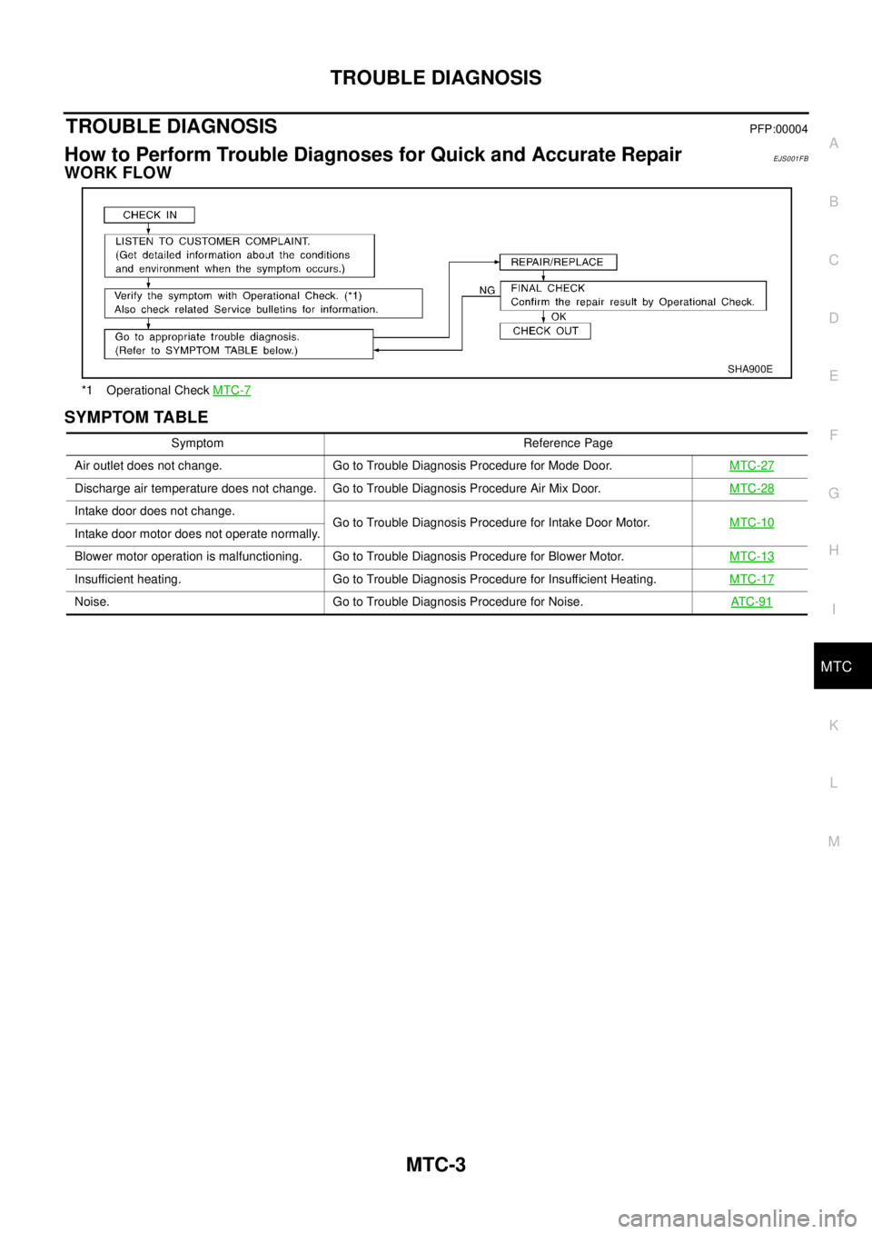
WORK FLOW
SYMPTOM TABLE
*1 Operational CheckMTC-7
SHA900E
Symptom Reference Page
Air outlet does not change. Go to Trouble Diagnosis Procedure for Mode Door.MTC-27
Discharge air temperature does not change. Go to Trouble Diagnosis Procedure Air Mix Door.MTC-28
Intake door does not change.
Go to Trouble Diagnosis Procedure for Intake Door Motor.MTC-10
Intake door motor does not operate normally.
Blower motor operation is malfunctioning. Go to Trouble Diagnosis Procedure for Blower Motor.MTC-13
Insufficient heating. Go to Trouble Diagnosis Procedure for Insufficient Heating.MTC-17
Noise. Go to Trouble Diagnosis Procedure for Noise.AT C -9 1
Page 2644 of 3066

MTC-8
TROUBLE DIAGNOSIS
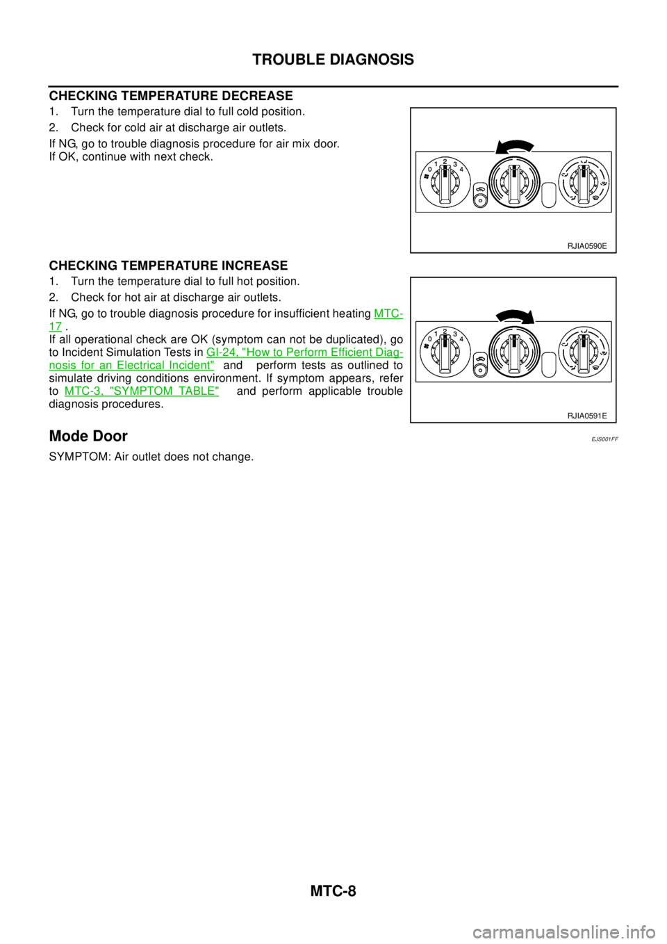
CHECKING TEMPERATURE DECREASE
1. Turn the temperature dial to full cold position.
2. Check for cold air at discharge air outlets.
If NG, go to trouble diagnosis procedure for air mix door.
If OK, continue with next check.
CHECKING TEMPERATURE INCREASE
1. Turn the temperature dial to full hot position.
2. Check for hot air at discharge air outlets.
If NG, go to trouble diagnosis procedure for insufficient heatingMTC-
17.
If all operational check are OK (symptom can not be duplicated), go
to Incident Simulation Tests inGI-24, "
How to Perform Efficient Diag-
nosis for an Electrical Incident"and perform tests as outlined to
simulate driving conditions environment. If symptom appears, refer
toMTC-3, "
SYMPTOM TABLE"and perform applicable trouble
diagnosis procedures.
Mode DoorEJS001FF
SYMPTOM: Air outlet does not change.
RJIA0590E
RJIA0591E
Page 2653 of 3066

TROUBLE DIAGNOSIS
MTC-17
C
D
E
F
G
H
I
K
L
MA
B
MTC
COMPONENT INSPECTION
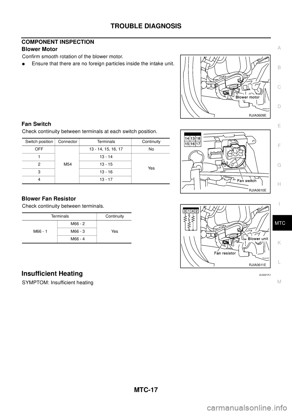
Blower Motor
Confirm smooth rotation of the blower motor.
lEnsure that there are no foreign particles inside the intake unit.
Fan Switch
Check continuity between terminals at each switch position.
Blower Fan Resistor
Check continuity between terminals.
Insufficient HeatingEJ S00 1F J
SYMPTOM: Insufficient heating
RJIA0609E
Switch position Connector Terminals Continuity
OFF
M5413 - 14, 15, 16, 17 No
113-14
Ye s 213-15
313-16
413-17
RJIA0610E
Terminals Continuity
M66 - 1M66 - 2
Ye s M66 - 3
M66 - 4
RJIA0611E