parking brake NISSAN X-TRAIL 2003 Electronic Service Manual
[x] Cancel search | Manufacturer: NISSAN, Model Year: 2003, Model line: X-TRAIL, Model: NISSAN X-TRAIL 2003Pages: 3066, PDF Size: 51.47 MB
Page 2676 of 3066

PB-10
SERVICE DATA AND SPECIFICATIONS (SDS)
SERVICE DATA AND SPECIFICATIONS (SDS)
PFP:00030
Parking BrakeEFS000D2
Ty p eDS17H
Brake liningStandard thickness (new) 3.5 mm (0.138 in)
Repair limit thickness 1.5 mm (0.059 in)
Drum (disc)Standard inner diameter (new) 172 mm (6.7 7in)
Wear limit of inner diameter 173 mm (6.81 in)
Lever stroke [operating force 196 N (20 kg,44 lb)] 6 to 7 notches
To t a l s t r o k e18 notches
Brake warning lamp strokeWithin 1 notch
Page 2766 of 3066
PS-6
STEERING WHEEL
STEERING WHEEL
PFP:48430
On-Vehicle Inspection and ServiceEGS0004E
PLAY INSPECTION
1. Turn steering wheel to straight-ahead position. Start engine and lightly turn steering wheel clockwise and
counter clockwise until front wheels start moving. Measure travel to starting point on circumference of
steering wheel.
2. If play is outside specifications, check following parts for proper installation: steering gear assembly, front
suspension, axles, and steering column
lCheck steering wheel for vertical, horizontal, or axial play.
lLift vehicle and check steering gear mounting bolts and nuts for looseness.
NEUTRAL POSITION INSPECTION
lAfter the wheel alignment inspection, carry out the neutral position inspection. Refer toWT-4.
lBefore removing steering wheel, check steering gear neutral position.
1. Set vehicle to straight-ahead position, and check that steering wheel is in neutral position.
2. If it is not in neutral position, remove steering wheel, and install again in properly.
3. If it is not adjusted within two teeth from center of gear, loosen tie rod lock nut. Then turn it to opposite
direction to adjust until amount of left and right becomes equal.
STEERING TORQUE CHECK
1. Stop vehicle on a dry flat paved road and apply parking brake.
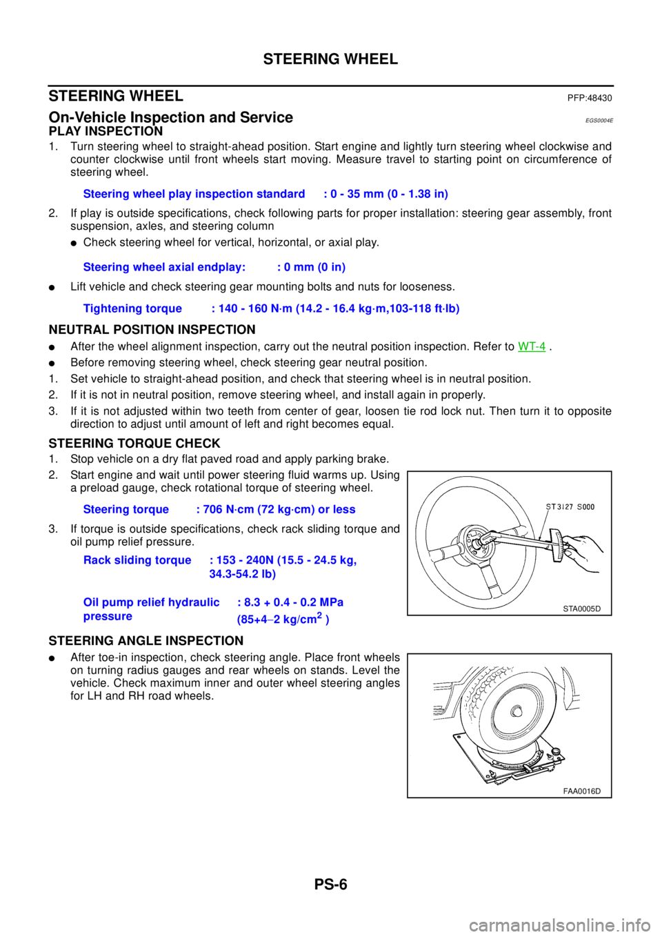
2. Start engine and wait until power steering fluid warms up. Using
a preload gauge, check rotational torque of steering wheel.
3. If torque is outside specifications, check rack sliding torque and
oil pump relief pressure.
STEERING ANGLE INSPECTION
lAfter toe-in inspection, check steering angle. Place front wheels
on turning radius gauges and rear wheels on stands. Level the
vehicle. Check maximum inner and outer wheel steering angles
for LH and RH road wheels.Steering wheel play inspection standard : 0 - 35 mm (0 - 1.38 in)
Steering wheel axial endplay: : 0 mm (0 in)
Tightening torque : 140 - 160 N·m (14.2 - 16.4 kg·m,103-118 ft·lb)
Steering torque : 706 N·cm (72 kg·cm) or less
Rack sliding torque : 153 - 240N (15.5 - 24.5 kg,
34.3-54.2 lb)
Oil pump relief hydraulic
pressure: 8.3 + 0.4 - 0.2 MPa
(85+4-2kg/cm
2)
STA0005D
FAA0016D
Page 2803 of 3066
WHEEL HUB (4WD)
RAX-7
C
E
F
G
H
I
J
K
L
MA
B
RAX
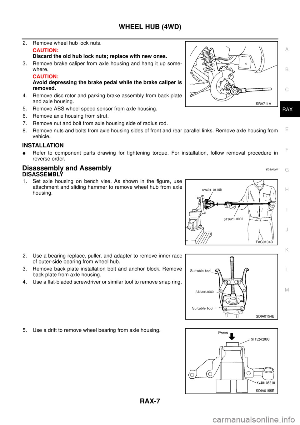
2. Remove wheel hub lock nuts.
CAUTION:
Discard the old hub lock nuts; replace with new ones.
3. Remove brake caliper from axle housing and hang it up some-
where.
CAUTION:
Avoid depressing the brake pedal while the brake caliper is
removed.
4. Remove disc rotor and parking brake assembly from back plate
andaxlehousing.
5. Remove ABS wheel speed sensor from axle housing.
6. Remove axle housing from strut.
7. Remove nut and bolt from axle housing side of radius rod.
8. Remove nuts and bolts from axle housing sides of front and rear parallel links. Remove axle housing from
vehicle.
INSTALLATION
lRefer to component parts drawing for tightening torque. For installation, follow removal procedure in
reverse order.
Disassembly and AssemblyEDS00067
DISASSEMBLY
1. Set axle housing on bench vise. As shown in the figure, use
attachment and sliding hammer to remove wheel hub from axle
housing.
2. Use a bearing replace, puller, and adapter to remove inner race
of outer-side bearing from wheel hub.
3. Remove back plate installation bolt and anchor block. Remove
back plate from axle housing.
4. Use a flat-bladed screwdriver or similar tool to remove snap ring.
5. Use a drift to remove wheel bearing from axle housing.
SRA711A
FAC0104D
SDIA0154E
SDIA0155E
Page 3013 of 3066

TROUBLE DIAGNOSIS
TF-43
C
E
F
G
H
I
J
K
L
MA
B
TF
REFERENCE STANDARD TABLE
Specifications defined by circuit tester
NOTE:
*1:If a circuit tester for measuring voltage is used for the check, do not forcibly extend any connector terminals.
*2:4WD warning lamp ON/OFF timing
*3:Unit name is indicated by the one used in circuit diagram (4WD solenoid valve). However, it is "E-TS SOLE
NOID" in CONSULT-II data.
Te r m i n a l N o .
Location
Standard*1(Note) Check points when
result was malfunctioning
+-
3 Power supply Ignition switch ON Battery voltage (approx. 12V)Control unit power supply
circuit
11 5
Body
grou
ndGround - Control unit ground circuit 11 3
111
108
106
104
74WD warning lamp
*24WD warning lamp ON
4WD warning lamp OFFApprox. 0V
Battery voltage (approx. 12V)4WD warning lamp and
harness
16AUTO indicator
lampAUTO indicator lamp ON
AUTO indicator lamp OFFApprox. 0V
Battery voltage (approx. 12V)AUTO indicator lamp and
harness
6LOCK indicator
lampLOCK indicator lamp ON
LOCK indicator lamp OFFApprox. 0V
Battery voltage (approx. 12V)LOCK indicator lamp and
harness
1024WD solenoid valve
(E-TS solenoid
valve)
*3At vehicle stop engine idling Battery voltage (approx. 12V)4WD actuator relay sole-
noid valve and harness
18 4WD actuator relay At vehicle stop engine idling 2 V or lower4WD actuator relay and
harness
2 G-sensor power
supply1
At ignition switch ON (vehicle hori-
zontal stop condition)Approx. 8 V
G-sensor and harness
32 Longitudinal G-sen-
sor 1Approx. 2.5V
22Throttle position
sensorWide open throttle
Closed throttleApprox. 4.0 V
Approx. 0.5 VThrottle position sensor
and harness
24Parking brake
switchIn parking position
In other than parking position-Parking brake switch and
harness
264WD mode change-
over switch AUTO4WD mode change-over switch:
2WD
4WD mode change-over switch:
other than 2WDSW ON: Approx. 0 V
SW OFF: Approx. 5 V4WD mode change-over
switch and circuit
274WD mode change-
over switch LOCK4WD mode change-over switch:
LOCK
4WD mode change-over switch:
Other than LOCKSW ON: Approx. 0 V
SW OFF: Approx. 5 V4WD mode change-over
switch and circuit
39CAN communica-
tion L line---
48CAN communica-
tion H line---
ON: When ignition switch is turned ON (before engine starts) or when malfunction is
detected
OFF: After engine is started (When the system is in normal condition)
Page 3014 of 3066

TF-44
TROUBLE DIAGNOSIS
Specifications defined by CONSULT-II
Check air pressure of tire under normal condition.Items to be monitored ContentsData monitor
(Reference)
Check points when result
was malfunctioning ConditionReference values in
normal operation
DECEL G-SENSOR (G)G-sensor operating
conditionWith vehicle stopped
on flat road.±0.15 G G-sensor and harness
THRTL POS SEN (V)Throttle valve open/
close conditionClosed throttle to wide
open throttleWhen closed throttle:
Approx. 0.5V
Throttle position sensor
and harness
When wide open throt-
tle: Approx. 4.0 V
ENGINE SPEED SIG
(STOP/RUN)With engine runningEngine speed below
400 rpmSTOP
Engine speed signal circuit
Engine speed 400 rpm
or higherRUN
E-TS ACTUATOR (ON/OFF)4WD actuator relay
(4WD actuator relay)
activation conditionVehicle stop (Ignition
switch ON)OFF4WD actuator relay (4WD
actuator relay) and har-
ness
Engine running ON
G-SEN VOLT (V)G-sensor power sup-
ply conditionWith vehicle stopped
on flat road.Approx. 8V (reference
value)G-sensor and harness
BATTERY VOL (V)Battery voltage sup-
plied to control unitIgnition switch ON Approx. 10 - 16 VControl unit power supply
circuit
4WDWARNLAMP(ON/
OFF)4WD warning lamp
ON condition4WD warning lamp
ONON4WD warning lamp and
harness
Refer to "4WD Warning
Lamp". 4WD warning lamp
OFFOFF
4WD MODE SW
(AUTO LOCK 2WD)Input condition of
4WD mode change-
over switchEngine running, vehi-
cle stopped, switch
pressed–4WD mode change-over
switch and circuit
4WD MODE MONI (AUTO,
LOCK, 2WD)Output condition of
4WD mode indicator
lamp signalEngine running, vehi-
cle stoppedUsing 4WD mode
change-over switch4WD mode indicator lamp
and circuit
DIS-TIRE MONI (mm)Improper size tire
installed condition–0-4mm,4-8mm,
8mm -Front/Rear tire size differ-
ence, wear condition
PBRAKESW(ON/OFF)Parking brake switch
operating conditionParking brake
depressedON
Parking brake switch and
harness
Parking brake not
depressedOFF
SPEED MTR O/P (km/h)Output condition of
vehicle speed for
speedometerWhile vehicle is
stopped0km/h(0MPH)
Speedometer and harness
Vehicle runningAlmost in accordance
with the wheel speed
sensor display
ABS 4WD COMMEPS/TCS/ABS con-
trol unit operating con-
ditionIgnition switch ON OKESP/TCS/ABS control unit
and circuit
CAN COMM (OK-NG)CAN communication
signal conditionIgnition switch ON OKCAN communication sig-
nal (OK-NG) condition is
displayed
Page 3017 of 3066

TROUBLE DIAGNOSIS
TF-47
C
E
F
G
H
I
J
K
L
MA
B
TF
8. Touch "MONITOR START".
9. Screen of data monitor is displayed.
Display item list
Item (Unit)Monitor item selection
Remarks
ECU INPUT SIG-
NALSMAIN
SIGNALSCAN DIAG SUP-
PORT MNTRSELECTION
FROM MENU
ENG SPEED SIG (STOP/
RUN)´´-´Condition of engine
(STOP/RUN) is dis-
played.
BATTERY VOLT (V)´--´Indicates voltage sup-
plied by 4WD control
unit
G-SEN VOLT (V)´--´G-sensor power sup-
ply condition (ON/OFF)
THRTL POS SEN (V)´´-´Indicates throttle posi-
tion sensor signal volt-
age
ETS ACTUATOR (ON-OFF) -´-´4WD actuator relay
ON/OFF condition
4WD WARNING LAMP
(ON-OFF)-´-´Indicates 4WD warn-
ing lamp operating con-
dition
ETS SOLENOID (A) -´-´Current supplied to
4WD solenoid valve
DECEL G-SEN (G)´´-´G-sensor operating
condition
4WD MODE SW
(AUTO, LOCK, 2WD)-´-´4WD mode recognized
by control unit
4WD MODE MONI
(AUTO, LOCK, 2WD)-´-´Output condition of
4WD mode indicator
lamp signal
DIS-TIRE MONITOR (mm) -´-´Improper size tire
installed condition
PBRAKESW(ON/OFF) -´-´Indicates parking brake
switch ON/OFF condi-
tion
SPEED MTR (O/P) (km/h) -´-´Indicates vehicle speed
recognized by meter
control unit
CAN EFFECT (OK-NG) -´-´CAN communication
signal (OK/NG) condi-
tion is displayed.
TCS FAIL SIG (ON-OFF) - - -´TCS fail signal condi-
tion is displayed (ON-
OFF)
EBD FAIL SIG (ON-OFF) - - -´EBD fail signal condi-
tion is displayed (ON-
OFF)
ABS FAIL SIG (ON-OFF) -´-´ABS operation (ON-
OFF) condition is dis-
played.
CAN COMM (OK-NG) - -´-CAN communication
signal (OK/NG) condi-
tion is displayed.